Showing posts with label Horizontal Stabilizer. Show all posts

Saturday, January 7, 2012

425 hours - finishing up elevator rivets and riveted bottom of trim tab

Editor's note on 1-17-2012. Originally I posted some pics of the position and type of rivet sets that I installed in my flange yoke that were incorrect. I have since edited those sections of this post to show the correct sets and their correct position in the flange yoke. Apologies to any builders following my blog if this led to any confusion.

So I seem to have some trouble adjusting the depth of my rivet sets in my hand squeezer. After setting the majority of of the top and bottom side rivets on the left elevator, I went back with my depth gage to check the rivets, and every one of them was set just a tad shy of where I normally like them. I have met some builders who state that the shop head of the rivet is supposed to sit just inside the hole, without any play, in order to determine if the shup head has been set correctly. Then I ahve attended classes, watched videos, adn read instructions for tools that state that the rivet head should never fit inside the hole, and this is the appraoch that I have always taken.

I am certain this will qualify as one of those never ending debate topics on VAF forums. IN any event, I needed to readjust the depth of my rivet sets and go back and squeeze each rivet again just a bit more to get them to ook the way I wanted. The problem arose from trying to check rivets on the top sides of the spars and ribs after squeezing them. My crummy progressive lense glasses end up giving me the perception that the rivets are set correctly as I check them with the gage, but when I flip the part over and check those same rivets that are now face up on the bottom (easier to see the gage sitting on the rivet), I see that all the shop heads are sliding inside the rivet hole of the gage.

Anyway, after getting that resolved, it was time to turn my attention to the trim tab. What an operation that turns out to be. This is yet another exercise of determining the correct positioning, clamping, tool selection, and technique to accomplish the job. I tried to take some pics that you don't normally see on most builders logs to help dispell some of the mystery behind how this works. So here we go....

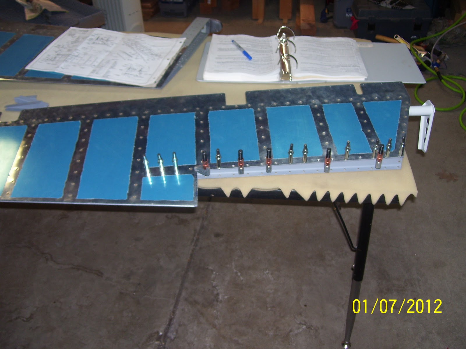
First is my clamping setup. You supposed to rivet the trim tab spar to the bottom of the trim tab skin first. The spar is Z shaped, and requires either a flange yoke or a long extension back rivet set to accomplish this correctly. I chose to use the flange yoke technique. TO start, you need to clamp the bottom skin down flat on your bench. I used two small hobby sized bar clamps that were able to fit inside the ends of the trim tab skin, and also helped lift the top skin up just a bit, which you will need to do to fit the flange yoke inside to set the rivets. Note how the skin is raised up off of the top of the spar on the outboard end of the trim tab.

Start with all bottom holes clecoed, and remove one from the end to start riveting. You basically rivet one hole and then move to the next one, removing one cleco at a time. this method worked out pretty well. TO get the skin to raise up far enough to get the yoke in there you need to put a wedge or piece of wood inside the skin to force the skin to open up just a bit. I used my trusty 1x2 blocks that have been with me since day one of the build as shown below:


If I had it to do over again I would have cut some wood to form a wedge, which would work a bit better than square blocks of wood like I used, but they still did the job. Next was deciding which rivet sets to use, and which way to install them in the yoke. I went through several girations of this, until I finally figured out what I needed as shown in the next pic:


SO I ended up using the 1/8 inch thick x 1/2 inch wide flat set on the bottom, or in the above pic it's on the left, and the 3/8 inch wide x 1/2 inch long flat set on the top of the yoke, or in the pic it is on the right. This allowed me to ensure that I had enough of the flat set on the bottom covering the flush head of the rivet, and the longer set on the top allowed me to reach behind the trim tab front spar and squeeze the rivet shaft down to the proper depth. It worked very well.
Next was trying to determine how I was going to keep the rivets in place, since they would need to be inserted from the bottom, based on the way that I ahve clamped everything to the bench. My first decision was to use back rivet tape to hold them into place. Seemed like a good idea, but the tape was not working out very well for me. This was most likely because I was still trying to figure out how to best position the squeezer, and during that time on the first rivet I messed up the tape, which caused the rivet to slip out.

So I decided to try another solution for this which up until now I had never really done before. I decided to pre-squeeze, or swell the rivets just a bot before inserting them into the rivet holes, to force them to stay in place once they were inserted. I had read about this technique, but had not had an opportunity to try it. First time for everything......

The process involves taking a rivet and inserting in between the two rivet sets in the squeezer, as show in the next pic. The tricky part is quezzing it down just far enough to allow it to still insert inato the hole, but tight enough to where it will remain in place and will not fall down or out of the hole. It does not take much to do this, and finding the right pressure to apply on the squeezer can be a bit of a challenge. After a couple of attempts I pretty much had it down to rough science:


The set combination shown in the above pic is actually the reverse of the arrangement I used to set the rivets, so don't be confused by the reverse order shown here. Just center the rivet up between the two sets, and apply a small amount of pressure to swell up the rivet shaft just a bit. Then insert the rivet into the hole. It helps if the rivet is as much in the center of the rivet set as possible. I found that the rivets would sort of snap into position and stay there if the shaft was swelled just the right amount. If you swelled them too much the rivet would not go into the hole all the way and you would have to try another rivet with a little less pressure.

The next pic probably does the best job of showing how the squeezer needs to be positioned for this task. Yup another FAA shot to prove that I am the insane idiot that is actually building this thing, even it if it is only showing the bald spot on the top of my head. Yikes!

The steps invlolved, at least the ones that I took, are as follows:
1. Started with rivet inserted into one hole, clecoes in all other bottom holes, working from the outboard or small end of the trim tab toward the inboard or root/large end. Why in that sequence? Because I wanted to tackle the hard holes first. The outboard holes are harder to rivet because the skin is much harder to left out of the way at the smaller end. Start with the sets slightly farther apart than needed so that you can determine the proper depth to set the rivets.
2. Lift the top skin up far enough to be able to see the shaft of the yoke as you slide it behind the spar web adn over the rivet shaft.
3. Slide the yoke into poistion over the rivet from the end, and gently apply pressure to the handles of the squeezer and watch the top head come down over the shaft of the rivet. Move the squeezer as needed so that the rivet shaft is centered as much as possible over the rivet shaft.
4. With the squeezer into position on the top, bend down and focus your attention on the bottom set which is over the flush head of the rivet and the bottom trim tab skin. Make certain that this rivet set is sitting flat over the skin and on the rivet head, and then squeeze a way. I found that I needed to use my left hand initially to hold the top skin back so that I could slide the squeezer into position with my right hand. Once I had enough pressure to just hold the top set in place over the rivet shaft, I could let go of the top trim tab skin, and use both hands to squeeze the rivet. This also helped ensure that the bottom set remained flat on the rivet head and the skin. This is the step you see me performing in the above pic.
5. Once the rivet is squeezed, take your left hand and hold the top skin up again so that you can remove the squeezer the same way it was inserted out the end of the trim tab.
6. Check the rivet t ensure it is set correctly. If not, adjust the depth of the sets and squeeze it again if necessary.
7. Remove the cleco for the very next hole, and start the process all over again.

Note that the squeezer handles are facing down, and not up. Took me a while to figure out that this is the way I needed to position it to squeeze these rivets.

First rivet is set successfully - YAY!


This is the starting position of the squeezer as you start to slide it into position. You can see why you need to use your left hand to hold up the skin in order to allow the top of the yoke to slide into position. It does take some force to position the yoke in place on this smaller end. It gets easier as you move toward the root end of the trim tab:


This next pic turned out blurry, but I am trying to show that when you get down to the last three rivets on the bottom, pay very close attention so you don't mess this up. You can set the very last rivet with the squeezer, but DO NOT set the next two rivets until the you have the E717 and E718 trim tab control horn brackets in position on the bottom of the trim tab. These holes will also require at least a 3-4 rivet instead of the 3-3.5 rivets used on the other holes. Since I am using riblets in the ends I also needed to wait until those are installed before I set bottom rivets number two and three from the root of the trim tab. I cannot install those permanently until the trim tab is final fitted into position on the elevator.


It shows the last rivet installed (Squeezer was inserted from the root side for this last rivet due to the clecoes for the other two holes being in the way).

A nice line of rivets shown here - every one of them set successfully:


Next are a few pre-squeezed rivets that I ended up over squeezing just a bit. They would not fit into the holes, even after using my large mushroom flush set to try to push the rivet through the hole. So I used some pliers to grab the head of the rivet and pull it back out of the holes, and got a different rivet and tried again.

Next is the trim tab bottom side. ALl rivets nice and flush to the skin. Glad I am almost done with these rivets. I was worried that I might mess up the skin while trying to set these, but it worked out fine.


Next is a little issue that I noted while browsing through Steve Riffe's builders log. The trim tab control horns attach to the bottom of the trim tab skin at the root. to try to prevent corrosion, the surface of the trim tab skin that mates to the two control horn halves should be primed or otherwise treated. I guess there have been reports that this is one of the areas for water to collect and where corrosion is most often found. So I tool the time to prime the surface of the skin where it contacts the parts for the control horn. Here I ahve masked it off for priming:

And here is the skin all primed:


Lastly are some shots of the top side of the elevator after getting those rivets set. The clamps you see are holding the top of rear spar to the skin in preparation for the next step, which is to fit the other half of the trim tab hinge adn final fit the trim tab assembly to the elevator. After that is done, only the trim tab servo remains. Then I get to haul the horizontal stab down off the wall to assemble and trial fit the elevators - -I can hardly wait!!!!


Monday, January 24, 2011

HS hanging above the workbench


I think that I was so exhausted by the time that I finally finished riveting the HS together that I forgot to include a pic that show my solution to one of an airplane builder's favorite questions: So where do ya put that finished part till ya finish puttin' the rest of it together? As shown, I had to get up on the shelf that sits above my workbench, screw in some cushioned hanging brackets, and suspend the HS by the rear spar. It sits there waiting patiently, until I get the elevators finished, which is the last part of the tail kit.

Monday, November 1, 2010

150 hours back on the build again


Just when you thought I had vanished off the face of the earth, I'm back! After a summers-worth of home projects, and hunting season all but over, I finally manage to start working on the plane again - just in time for the cold weather! So to pick up where Ileft off, after Oshkosh 2010 I had repaired my blunder on the HS, but I still had some doubts about the fit of the end rib to the rear flange on the right side. There was a small gap that indicated that the flange was not quite seating properly. This is a structural concern and I finally stopped wrestling with the decision and decided to drill out the 2 AN470 rivets and do them over again. Read the series of posts about my major repair and you'll understand why I was hesitant to try to drill out any more AN470 rivets. This pic shows the gap. I was able to refit this and close up the gap successfully, and re-do the last flush rivet on the end of left side that I had also messed up, and now the HS is hanging up on the wall above my work benches, waiting on assembly with the fuselage someday down the road.
Here is the 8'4" long HS for my RV8. Just needs some fiberglass tips on the ends that I will install later. I'll probably pull it down again when my elevators are done just so I can test fit them to the HS and dream about the day when it's time to attach them to the fuselage for the very last time.


Now on to the Vertical Stabilizer, or what most folks call "the tail" or "the fin." You can see the frame or skeleton of the VS on the table just to the right of me. More VS pics will follow..

Saturday, May 22, 2010

Repair done on Wednesday, May 19, 2010


Ron Duren to the rescue (Again). He graciously accepted my invitation to drive to my house to buck 4 rivets to finish the repair work that took me most of the week to complete. He handled the bucking bar (left hand), while I drove the rivet gun (right hand). Notice the cool EAA T shirt that defines a pilot, and, yes, the wing parts still in the crates in the back ground - still working on that project.


And the finished task - 4 nicely set rivets, 2 on each side of the repair flange. Although standard aluminum patch practices may call for at least one more rivet on the spar-side of the repair, I stuck with 2 rivets on each side. The reasoning is that the skin is providing support with all the rivets that are attaching it to the spar and to the rib, so I think that there is adequate support in this area. I used an offset dome headed cup set for the rivets that attach the new flange to the spar web, which is about 5 inches longer than the normal cup set I would use for AN470 structural dome headed rivets. This allowed sufficient clearance of the rivet gun from the skins so that they would not get all banged up during the riveting process. Note that the repair was placed on the forward side of the spar web, and not the back, although when I marked the holes for the location of the rivets, I had it placed on the aft side of the spar web. This was because this was the only side that I could fit a straight drill bit (used a 12 inch extended number 30 drill bit to drill the holes.) Yes, I could have used my angle drill attachment to drill the holes from the other side, but I find this tool to be very inaccurate in terms of being able to drill a nice, straight hole, unless you can slap it in a vise to keep it from moving. So I opted to drill from the back side using a longer drill bit, and it worked out pretty well that way.

And from the other side - 2 more nicely set rivets, all in the original holes of the new rib that arrived from Van's "just in time." For some reason we had a little difficulty with the holes in the repair piece lining up with the holes in the rib after the piece was riveted to the
spar. This was strange to me because everthing had clecoed together perfectly before we started riveting. If I had one thing to do differently about this repair (hopefully I will not have to do this again but...) I would not match drill the holes in the rib to the repair piece until AFTER I riveted the part to the spar web. What I did this time was match drilled the rib holes to the repair piece after clecoeing the piece to the spar, but BEFORE it was riveted to the spar. If I would have waited until after I riveted the piece to the spar flange to drill the holes for the rib attach points, they would have lined up perfectly, which caused the mis-alignment of the holes on the other side. I can only guess that the act of riving the rivets to attach it to the spar pulled everything up tightLesson learned, but hopefully will not need to be repeated! Whew, that was a lot of work! But at least its done, and so is the HS riveting, for the most part. More on the finishing touches later.... Thanks again Ron for all the help.

HS repair cont'd


Another blurry pic. Shows progress with th nibbler. The only draw back is that you cannot control the precision of each cut very well, so some are deeper than others. Here you can see some of the little pieces that have to be nibbled away - almost there...


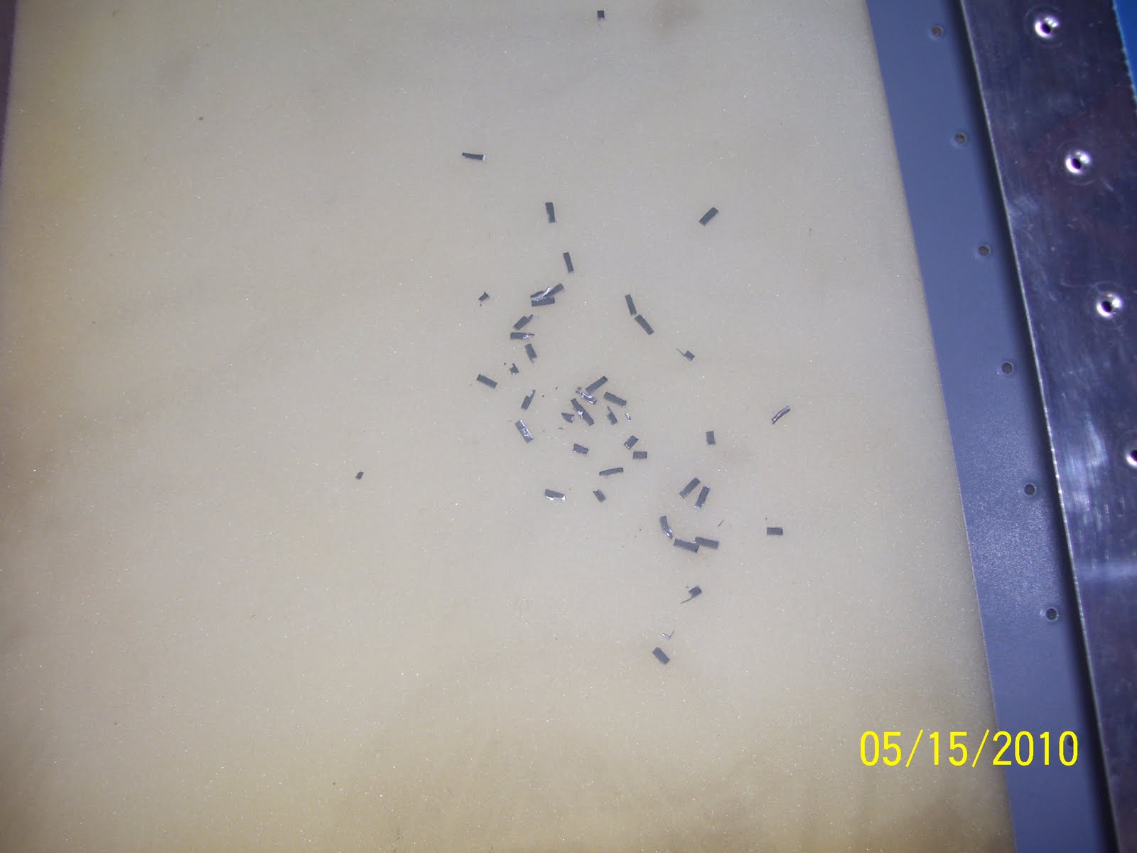
For anyone with experience in such matters, no this is not mouse poop, even though it looks like it from a distance. Believe, me, unfortunately I know what mouse poop looks like! No sign of them in the last 8 months or so, so that's a good thing. These are the remnants of the metal removed from the flange by the nibbler.


The business end of the nibbler in its non-cuttting state


Now in the cutting position. It generally will remove about 1/8 inch of material by about 1/4 inch with each cut.


The end result after nibbling and grinding the edge to a smooth edge with no burs. You can also see the marks I have made on the spar flange when trial fitting the new flange in place. That was a lot of fun by the way, because I had to use 3 hands and some tape to hold everything into place. Then I had to fit my sharpee in there to draw some reference lines and mark the hole locations in the spar web. All the trial fitting had to be done with the end rib clecoed in place. Needless to say, since I was the only one present during this delicate balancing act, I have no pics of the part taped into place during this operation.


Another shot showing the degree to which the flange was trimmed. I only cut enough to remove the bend, leaving as much of the straight part of the spar web in tact. All of the metal dust and chips from drilling/nibbling were cleaned out of the areas as well. You don't want any of this material settling into the crack and crevaces where they can start to fatigue the metal between the spar and the skin over time. Everything was spic and span before closing it all up, hopefully for the last time.

Repair of HS Tip - Hobbs 140 hours


So the repair process began. All through last week, and ending with Ron coming over to help me buck the 4 critical structural rivets for the flange repair and the re-attachment of the end rib to the HS. A series of pics of the process follows:
A bit blurry - did I ever say how much I don't like digital cameras, except that you did get instant electronic pictures I guess. This shows the top hole that was also drilled through. This entire flange had to be cut and trimmed away, and a replacement flange fabricated and riveted in its place.

Just some of the many tools used to complete this repair, and a shot of the more or less finished part that I had to cut, bend, and drill. The wood form block is the same one from earlier posts where a 1/8 inch radius bend was required. The angle finder was used to verify that the bend was exactly 84 degrees to match the angle from the forward spar to the side of the end rib where everything attaches, resulting in a 6 degree angle, or the same angle that the roots of the spars and the support angle brackets were bent to long ago. The two holes have been measured and drilled to assure proper edge distance requirements are met. Other tools used were a nibbler, my dremel grinding wheels and articulating saw attachments, metal cutting saw blades, and more.....


Another bad pic - attempting to show the angle and how the part was positioned between the two blocks during the forming process


Fitting and sizing up the side that fits up against the inside of the rib. You can see the relationship of the rib holes to the flange. These are the two remaining holes that have to be drilled. The plan is to rivet the new flange to the spar first, then fit the new end rib into place, and use the existing holes in the rib as a guide to match drill the holes into the other side of the flange.


Shows the plastic hammer I used and the form blocks and the aluminum part in the vise and being formed. Just had to eyeball this a bit and make sure that I did not force the bend over the 84 degree mark. This is actually very easy to do, and my guess-timate was very close to where it needed to be - I was only about a half degree off. You just start tapping the hammer at the base of the bend and it starts to fold right over.

Shows the part up against the angle finder - 6 degrees - with a 1/8 inch radius - just as it should be.


Now for the other difficult part of the fix - how to trim off the damaged flange from the spar. Lots of measuring involved here - not to mention trying to decide what tool/method to use to remove the flange. The trick was to remove only enough material that would not compromise edge distance on the spar web, which meant only trimming off enough material right up to where the bend occurs, without removing any material running the length of spar web, if that makes sense. Then ensuring that it is straight and free from burs, all within the confines of a skin that is already riveted in place on the spar top and bottom. Dremel cutting wheel was out of the question - too much risk of skipping and cutting into the skin, causing even more problems. Hack saw was another possible solution - but it would have to be done by hand. In the end, as shown in the pic, I chose the nibbler (man I love this tool!) I could cut small chunks out at a time, with fairly precise control over the amount of material being removed. Yup, that's my fat hand in the foreground, next to the small opening at the end of the HS.

Wednesday, May 12, 2010

Good News/Bad News

So I was able to transport my almost-complete HS up to Erie Airport past Saturday, where one of the EAA chapters I belong to, Chapter 43, was having a hangar picnic. Lots of great food and great company. There were not one, but two completed RV 10s in the hangars, and so I spent a fair amount of time gawking at them, and drueling with envy at how big and roomy this home built airplane is. I met with a tech counselor, Bill Truax, who looked over the damage to my wing skin and basically told me that it could be filled, won't ever crack, and basically told me not to worry about it, and to KPR (keep pounding rivets). That was the good news.


Now for the bad news. Later that evening, after getting the HS back home, I should have simply started closing up the rear spar and the ends and called it good. Instead, there was one rivet that attaches the end rib on the right side that did not quite get set as well as I would have liked. So I thought that I would drill out this rivet and and replace it, and then finish everything up after that. the first removal went without incident, but the attempt to reset the rivet resulted in a very badly set rivet, so I made the decision to drill it out as well, and try again. As the following picture shows, my drill slipped and I ended up drilling a new hole right through the end rib and into the spar flange that it was attached to. I then had to get creative with a pair of needle nosed pliers in order to snip away at the remaining rivet head in order to get it loose enough to remove. It did not matter, though, since the damage was already done.

A phone call to Vans yesterday, followed by a comfirming phone call to EAA HQ tech counselors today, resulted in a recommendation to:

a. Completely cut away the portion of the forward spar flange that connects to the end rib (not shown in this pic but I will add other pics as I affect this repair.)

b. fabricate a new flange part for the end of the forward spar that will need to be riveted onto the end of the web of the forward spar

c. Order a new end rib (done today), locate and final drill all the holes, debur it, dimple the holes, flute the edges, and prime it. Then finally try to rivet it in place once again.

Obviously this will set me back a bit from finishing the HS, having learned yet another very important set of lessons in the process. I'm sure this will not be the last time I have to figure out how to affect a repair like this, but, needless to say, I am very disappointed in myself right now, and in hindsight I should have left well enough alone. That said, you just have to press on when things like this happen, and realize that problems like these can still be resolved, albeit with a bit of extra effort.
The fabrication will take me some time to complete, because there are some precise measurements that have to be made for the correct size of the repalcement piece, and an 84 degree bend that needs to be made to properly line of with the web of the end rib. Lots of cutting, clamping, and drilling to do. Looks like the dimensions needed to fabricate the part are to use .032 inch thick alclad aluminum, and both sides of the piece will need to be about 1.5 inches long x 1.5 inches wide. The real dimension turns out to be about 1.65 inches x 1.39 inches in order to achieve flanges that are 3/4 of an inch wide on both sides. Bending metal is yet another specialized skill that one has to become familiar with, and it involves quite a bit of math skills and knowledge of metal properties in order to get it right. I won't bother listing out all the detailed formulas involved in figuring out the correct dimensions, except to say that I have spent most of my evening reviewing and calculating all of this. I figure this will set me back at least a week on the HS. Wish me luck I guess.

Friday, May 7, 2010

The whole HS assembly - almost there......


What a nice pic of an almost finish airplane part! I can't finish riveting the skins until I have a tech counselor look at my damaged skin this weekend. Hopfully the verdict will be that I can proceed without replacing the skin, and then I can finish attaching the rear spar, shown here clecoed into position. The remaining rivets can be squeezed instead of bucked - a welcome relief from all the bad rivets I had to drill out and replace thus far.


Riveting is definitely a skill that has to be practiced. Unfortunately, I am finding out that not even the courses that you take from EAA, or the project kits that you can work on, provide the same challenges that you experience on the real airplane parts. You have to learn how to feel the bucking bar, how to hold just right in many different positions, and how to hold the rivet gun, how to contort your body and hands into just the right position, and so on. It will definitely be a challenge when trying to do this on my own, but the good news is that the wing and fuselage parts are somewhat bigger, making them at least a little easier to work with.

Left Side HS Skin almost complete


With Ron's help, this is the bottom side of the left half of the HS, almost completely riveted together. The only thing remaining is to attached the other half of the stabilizer and then finish riveting the ends and the rear spar. The whole assembly turns out to be about 8 feet 4 inches long.

Installing Pop Rivets for the first time


Perhaps I should add some pics of the tools and rivets to this post to provide a better understanding of what pop rivets are and how they are installed. This pic shows the finished result after the pop rivet has been installed to the center rib section of the HS. Pop rivets have a long stem that sticks out from the top of the rivet about an inch and half or so, which fits into a specially designed, manually squeezed rivet gun. The stem of the pop rivet slides into the end of the rivet gun, then you insert the rivet into the holes of the pieces you are joining together, and then you start squeezing the handles together until you hear a "pop." The reason you need to use these rivets instead of the other type of rivets is that certain areas become closed off and are no longer accessible on one side of the part, so you can't get a bucking bar on the other side to drive the rivet. Such is the case once you have riveted both sides of the skin to the nose rib, and the front spar has been installed.
This method provides a way to install a strong rivet without having access to the other side of the part. As you squeeze the handle of the gun, the shaft pulls on the rivet, effectively mashing it up against the blind side of the part, until the rivet is fully set. This is when the stem gives way and breaks or pops out of the hole in the center of the rivet head. It's a bit startling when it happens, and it only takes a couple of pulls of the rivet handle to make it happen.
The "pop" is the sound of the rivet stem separating from the actual rivet. There are three pop rivets that had to be installed to attach the center nose rib, forward spar, and the main rib together. the tricky part was that all this had to be done by sliding the rivet and rivet gun into the small opening in the back of the HS skin. As usual, it's all about fitting large things in very small openings, and trying not to damage anything in the process. If you look close you can see where the rivet gun contacted the web of the rib and scuffed it up a bit. This just proves that I need to take my pop rivet gun and grind down the shaft so that it will not interfere with the part that is being riveted. You have to make these kinds of modifications to your tools from time to time.
The installed pop rivets have a small hole in the middle where the stem was located. It's easier to show someone than to explain how this process works, so I'll take some pics of the rivets and the gun to help understand this process.

Thursday, May 6, 2010

Another optical illusion


Another alclad mirror illusion. This is actually a pic looking inside the enclosed skin after riveting both sides of the center nose rib, which is the first thing that Vans instructs you to do. The actual rib is in the center of the photo, and the reflections from both sides of the skins are on either side of the nose rib.

Wednesday, May 5, 2010

A-riveting we will go...... A-riveting we will go....


So I asked Ron when he arrived last Saturday what he thought about the ding on the top side of the left HS skin, since he is also "knowledgable" about such things (he-he). His response was something like " well I tell you what, whatever we are going to do let's decide right now, before we start riveting!" meaning that before we pound hundreds of rivets into this skin I better make a decision. I decided that Van's had seen the photos and indicated that it looked like a fillable depression. and I guess I was also prepared to undo (drill out) any rivets should anyone else raise concerns. So I decided to KPR (Keep pounding rivets!) If nothing else, it would be excellent practice bucking and riveting with two people, which is something that you inevitably must do during certain phases of the construction of an RV aircraft. Here is Ron with the center nose rib riveted in place, and the left side skin clecoed to the rest of the frame on the bench.

Reflecting on the past few months - Hobbs Meter estimated at 110 hours. Priming for the First Time

I did some reviewing of my past posts and realized that it has been almost 5 months since I last updated the Hobbs meter on my progress. Sheeeesh, where does the time go? I remember January being unusually warm, and that was when I was busy dimpling and prepping/deburring the skins and other pieces. Then it got really cold and snowy through most of February, so not much was done during that month. Priming all the parts took a lot longer than I would have liked. A lot of that time was spent figuring out the process and preparation steps, and getting familiar with myspray gun settings, etc. So hopefully any future tasks for this will take much less time. I am estimating that my total time on the project is at least 110 hours now. I will start tracking this a bit closer from here on out.

Catching Up - Getting help with riveting

So you have seen my very ill-prepared attempt to start riveting my HS skins onto the frame. I have contacted several people from EAA HQ to local Tech Counselors to my friend Ron. This Saturday one of the local EAA chapters I belong to is having its annual picnic up at Erie Tri County Airport. One of the tech counselors suggested I bring it to the picnic where they can look at it in person. Sometimes pictures and describing things over the phone just don't quite cut it.

After I incurred the damage, I contacted Ron and asked him if he could come down and help me shoot all these rivets. Iwas no longer confident that doing this solo was something that I could do successfully. He gladly said that he could come down, so last Saturday we spent most of the afternoon riveting the skins to the HS frame. Lesson learned here - contact Ron or somebody to help BEFORE doing stupid things like attempting to rivet large pieces on a wobbly, uneven table at an improper height!

What a great afternoon that was. I learned a lot from Ron, and I can't even begin to tell anyone how valuable it was to have someone there with some experience to help you out. The following posts contain pics of all the activity over the past week. Thanks Ron for all your wisdom and help!

Tuesday, April 27, 2010

Now for something really funny - riveting the skins Begins


So what's funny about this? Just another in a long line of bad mistakes that I really need to figure out how to stop making. This happened on my second rivet while attaching the center nose rib to the top of the left HS skin per the plans. The "funny" part about this is that I managed to really gouge the skin very badly. Well, OK - that's not so funny, because I may now be faced with a decision to completely replace and redo all the work on this skin that I worked so hard to make perfect. Ok, so it's funny in a sad sort of way, because no less than an hour before doing this I sent an email to my friend Ron, saying that I was too afraid to try to buck these rivets all by myself, and asked if he would like to help. Then I went right out and tried to do exactly what I was afraid of doing, and now I get to deal with the result. Even more "funny" is the fact that Ron had made this exact same booboo on exactly the same rivet on exactly the same skin, but somehow I think that his ding was a little less severe than mine, but we'll see. In the mean time all riveting now comes to a screeching halt, while I contact technical counselors and get feedback from others to see of this is not so bad, or if I am ordering a new skin from Van's very shortly. As best I can tell, I did not puncture the skin, but the ridge on that divet is quite pronounced, and I am afraid that I really screwed it up. Such is the life of an airplane builder I guess.

On to the forward spar


After relatively good success and only a few bad rivets on the rear spar assembly that had to be drilled out, I started on the forward spar of the horizontal stabilizer. This proved to be a much more challenging experience. My success to failure ratio of riveting the forward spar together was only slightly more than 50%. That means for every two rivets I tried to put in, one of them was bad and had to be redone. Not a very good percentage, and certainly not very good for the self confidence factor either. This is a close up shot of the area where 4 very tightly spaced structural rivets are attaching multiple parts together, including the forward spar, two angle support brackets, and the inboard nose rib. If you blow this pic up you will see smiley faces all over the place. This is what happens when the rivet set becomes uncentered and starts to dig into the surrounding metal. It all happens in the blink of an eye. Another problem I encountered was the fact that the smily face on the second rivet from the top was so bad, that it forced the flange of the nose rivet to bend outward just a bit, so the mating surface between the spar and the nose rib flange is not fully in tact. I talked to Van's about this and they said that as long as the shop heads (on the other side of the rivets in this pic) are OK, this should not pose a problem. The skins are also part of the structure that provides the overall strength of the stabilizer, and they will serve to add strength to this entire area once they are riveted in place. So I left this "as is" and will build on.

Another Shot showing how the flange is bowed out from the spar flange just a bit. These surfaces should be flat against each other.
Rear side shop heads of the same area. These are meeting size and circumference measurements so I am leaving them as is.

Center bearing bolted onto Rear Spar


A shot of the Rear Spar with the center bearing bolted on. Yay, I finally got to use my inch/lb calibrated torque wrench to snug up these four bolts and nuts.

Monday, April 19, 2010

HS Rear Spar in progress


Rear Spar in progress. What you see here is the left side of the spar with the two support brackets in the middle of the spar web, with most of the top bracket rivets installed, and the bottom rivets in progress. The green tape is there to help me remember that I am not to drive rivets in these locations because either a hinge or a rib attach point is located there, and I need to wait until I get to those assemblies before I put any rivets in these holes. No sense in driving rivets just to end up having to drill them out later!. One other nagging problem that I need to figure out how to resolve is shown by the splotches all over the spar. What happened here is that my rivet gun started spewing tool oil all over everything, after I spent all that time cleaning and priming. That just made me flat ANGRY. Now I have to take soap and water and HOPE to get all that crappy oil off of everything before I can do my final assembly. That just really sucks! Lesson learned - I will no longer be adding tool oil to my tools just before every use, as I have now determined that they are all over oiled anyway. At this point I would rather see the tool sieze up than have to clean up this crappy mess again.

Sunday, April 18, 2010

Finally Pounding Rivets!

I thought this day would never come. I started assembling the horizontal stabilizer of my aircraft. The first step was to assemble the parts that make up the rear spar of the HS. These included two spar halves, two support brackets, and 5 hinges that will support the two elevators that make the plane move up and down. I thought that I was going to get to use my pneumatic squeezer on this assembly to same some riveting time, but I found that once again I did not seem to have the right tool for the job. The yoke on my squeezer was interfering with the flange on the spars, and this would not allow me to use it without grinding away some of the yoke.

Instead, I decided to pound these rivets using the rivet gun and a bucking bar. It had been a while since I had used them, and there are thousands more rivets that will require the use of these tools, so I decided to dive in and start riveting. I was doing fine until I got to one of the hinge brackets on the end of the right spar. As the picture shows, the rivet gun got a way from me a bit, and I did what is known as a smiley face all over the rivet head. Another rivet on the other side was noticeably out of place as well. So I needed to drill out these two rivets and start over.


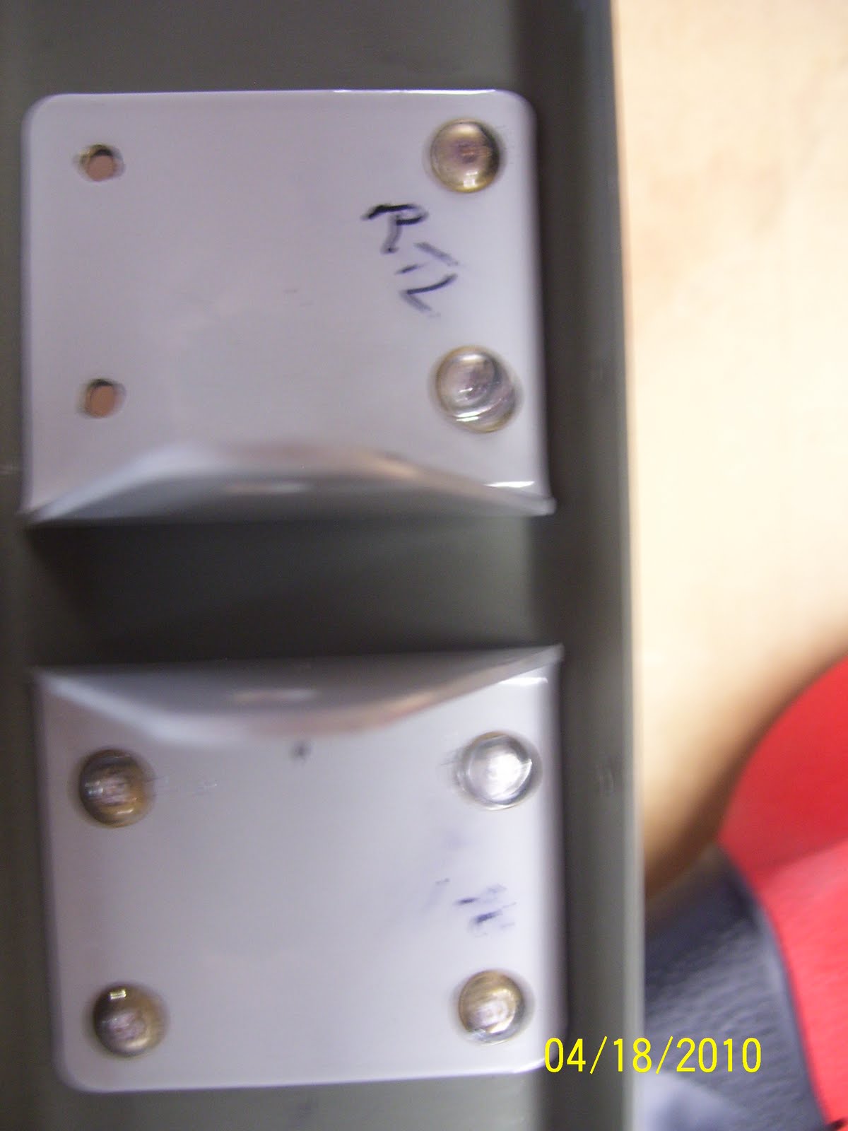
RTL stands for right Top Left, meaning that this is the outer elevator hinge bracket for the right side of the HS, that goes on the left side of the hinge assembly. Even more confusing is the fact that this pic will not transfer over correctly for some reason, and is shifted 90 degrees to the right. I found that I needed to mark everything correctly, because once you turn something upside down or backwards, you cannot tell which part goes where anymore.
If you look at the right side rivets, the two that are closet to the hinge point in the middle, you can see the difference between these rivets and the others that have been driven. these had to be drilled out and replaced, and although I was nervous about doing this, it actually worked out OK, and I drove two new rivets in their place that turned out just fine.

Thursday, April 15, 2010

A mirror maze!


Looks like some wacked out metal scaffold assembly, but its just the reflective Alclad coating bouncing off of both sides of the HS skin after all priming was completed. Quite the optical illusion oif you ask me. I've seen some polished airplanes that do this same thing over the entire aircraft.