Wednesday, May 31, 2017

Deburring holes and edges, scuffing ribs and LE skin for primer

 First things first - a shout out to fellow RV-8 builder and friend Steve Riffe, now living/flying in the Dallas area. We started our tail kits at about the same time in 2009, and he just received his airworthiness certificate for his finished airplane. N ow he can take his first flight and continue with phase 1 flight testing. See post on VAF here , and his builders log is at this location 

Its really great to see another soon-to-be-flying RV-8 make it to the finish line. Way to go Steve!!!!

Over the past several days I have been taking care of several small jobs. The first involved more trimming of the Left wing LE skin edges for the new access panel. I discovered that one of the edges was decidedly not aligned with the corners and was not straight. So I took a straight edge ruler and marked "straight" with the sharpee, and then carefully took the file and trimmed down the metal, being careful not to dig any more ridges into the skin. This next pic shows the result:

If you click on the above pic and view it in a larger resolution and look at the left and right edges you can see the problem. What happened is I filed away a little too much metal on the skin edges. leaving a small gap between the access panel cover and the edge of the LE skin.This happened because I forgot to stop filing after reaching the INSIDE edge of my sharpee line. Instead I kept on filing until the sharpee line was almost gone. Even the ultra fine sharpee can leave at least a 1/32 or 3/64 inch wide line, so you have to remember where to stop removing the metal.

Here is a close up that shows the gap better:


The funny thing is that this gap is much smaller than the Vans access panel and cutout for the original access panel LE skin. I think I have seen posts from other builders where they actually fabricate a new panel cover so that it fits better. Perhaps I will do the same, but for now I will leave it. I still have a lot of surgery to do to figure out how to close up the original hole, and right now that is just a bit more important.

Next is a pic showing the vinyl that I removed from the tip of the LE and the outer races for the rivet holes for each LE rib.

As I mentioned before, I am pretty certain that leaving the interior and exterior vinyl on the pre-bent edges of any skins applies a bit of extra force away from the wing ribs, making them just a little bit harder to bend into position when assembling the ribs. If you remove the vinyl from this area it reduces that stress a bit. Works for me. YMMV.

With the LE ribs completely disassembled I starting scuffing them in preparation for primer. I still need to clean them, but at least the hard part is done:
A couple of important notes about this for other builders. even though I took the time 2 years ago to use a small jewelers flat file to remove the bumps that result from the factory bending of the tip sections of each rib, I found that all of the ribs still needed to be filed a bit more. You can see the file I used in the middle of the above pic.

I made sure I rechecked all of these on each rib, because I was surfing the web one day and found a PDF file link to what I presume to the the new Section 5 of the Vans manual for the RV-14, which is much more informative and contains a lot more tips and tricks than my older Section 5 contains. One of the sections specifically called attention to making sure you do whatever is necessary to remove ALL bumps on the front of all leading edge and fuel tank ribs to prevent bumps from appearing in the skin when you start riveting everything together. they even had pictures and diagrams of how this should look.

My litmus test for this is a little bit visual, but mostly by feel. I ran my fingers over the tops and bent sides of each cutout on each rib, and if my finger gets stopped by a ridge, I went to town on it with the file until is felt reasonably smooth. I was surprised by how much more I had to dress these edges out until I was satisfied that they were smooth enough. It will shock you just ho much you need to thin down the edges of some of these sections. don't be bashful about this trimming if you don't want bumps in your LE wing skins after riveting.

I should have mentioned that prior to scuffing everything I deburred all the rivet holes in each LE rib. I honestly do NOT think I had ever deburred any of these holes in the remaining ribs, while i definitely deburred everything involved in the area of the mod that I am doing, I don't think the LE holes had ever been disassembled beyond that. I was amazed at how much some of the holes needed to be deburred.

One of the hardest things I had to do was deburring the inside of all the rivet holes that attach the top and bottom of the LE skin to the wing spar. The outer holes were easy because they are right in front of you, but I must admit I was not prepared for the need to do all of the inner holes. These were a pain for several reasons:

- They are hidden under the wing spar flanges so you have to bend and contort your body in weird ways to get to them all.

- With one side of the main wing skins clecoed in place, I was not able to get my electric drill with my deburring bit into position to debur one side of the holes. The other side was easy because the wing skin was removed. While I suppose I could have removed the mounted wing skins, I did not want to do this because they do help maintain the structure and placement of the frame. So I took the deburring bit out of my drill as I have done before, and twirled it between my fingers, while contorting myself even more while trying to blindly fit the tip of the bit into each inside hole. Easier to demonstrate than explain, but lets just say it was a major pain in the butt, and it leaves my fingers in a rather raw state after doing this for about 100 holes or so. Anyway, the wing spar holes are now deburred as well, so mission accomplished.

Here is a pic that kind of shows the area that needed to be deburred. I only focused on the top row of rivet holes for now, since those are the holes for the LE skin. I will have to do the bottom row of holes when  am ready to finish prepping the main wing skins, but that can wait.

And then finally, after a bit more precise vinyl removal on the inside of the LE skin, I started scuffing the inside of the LE skin. What follows is a series of pics that shows the overall scuff job of one side, and what appear to be rather deep scratches from all the mod work and fitting, installing and removing parts multiple times, and how those scratches seemed to scuff out pretty well with the scotch brite pad, indicating that the scratches were probably only as deep as the alclad coating of the metal.

And finally, since I will be priming another small batch of parts in the near future, I needed to get two more turkey basters to measure out both parts of the primer, just as I did a few weeks ago. Here is the uncontaminated "new" turkey baster that I got from King Soopers.

Next steps are to finish scuffing the other side of the LE skin, then wash and clean the ribs and skin, then prime them. Once that is done I will reassemble the LE and attach it on the wing spar so I can mark up the subskin for the new access panel opening and start trimming that lovely piece of metal to its final form, whatever that may be!

KPR!


Tuesday, May 23, 2017

Deburring Holes and removing More Blue Vinyl.

No pics tonight - just a quick update on the LE progress. I reviewed the work I did on the new access panel opening. I still have a bit of edge trimming, smoothing, and deburring to do, but other than that the panel opening is pretty much done. I am now mired in thought about how to manage the panel attach brackets for both holes. This is perplexing for me because I really want to trim away as much of the subskin as possible to lighten it up, but still leave the proper amount of material to serve as the mounting platform that I need.

After thinking about it, instead of jumping in a reassembling everything so I could put the LE back on the wing spar, I realized I needed to do some serious deburring of all the holes in the LE skin. I finished deburring all the new holes I drilled the other day for attaching the access panel attach bracket to the LE skin. But then I realized that most of the blue vinyl has remained on the LE skin since I received it many years ago. Even though I had match drilled all the rib holes and the wing spar attach holes, I have never fully deburred these holes, and so this was long overdue.

Before I could start deburring those holes, I needed to remove some vinyl using the tried and true soldering iron method and a straight edge. One thing about this that I ahve contended all along, is that this vinyl is a real problem with pre-bent surfaces such as the LE and tank skins, and the skins for the HS and the VS tail sections. The reason is that none of these skins is form fitting to the underlying rib structure. The skins are only pre-bent so far, and must be forced into their final positions over the substructure. This is how stressed-skins are designed, so that the skin ends up providing a certain amount of support to the total structure. The vinyl around the outer edges of these skins acts as a deterent to bending the skin to its final shape, especially the outer vinyl that goes around the outer leading edge of the skin.

I made a point to remove the vinyl in this area when building the HS, but somehow forgot to do this on the LE skins. So tonight I finally removed the small section of vinyl across the outer and inner edges of the front the LE skin. I also removed the vinyl along the rear spar attach holes and along the outside rib holes  I had managed to remove the vinyl a long time ago where the rib flanges meet the inner skin, to ensure that the rib-to-skin fit was as form-fitting as possible. But that was the only vinyl that I had removed after all this time.

Anyway, I got all the vinyl removed, saw how badly I have botched the rib flange rivet holes for those first two ribs that I have been working on for so long by having to re-drill through them way too many times, and did my best to debur those holes as much as possible. I am now fearing that those holes are much too big for a standard AN426 AD3 rivet, and I my be heading for ordering a new LE skin. But its a bit too early to throw in the towel, and I really won't know how bad this is until I dimple everything and prime it and start riveting.

Every time you have a pre-bent skin, there are 4 sides that have to be deburred - 2 on the outside and two on the inside. I managed to debur the holes on one of the outer sides tonight, so I have 3 more sides to do. I had almost forgotten how much "fun" it is to debur a million holes in a complex piece of aluminum. There sure was a lot of metal shavings on the ground after getting rid of all the burs that were in the holes on the skin - makes me a bit nervous since this skin is only .025 inches thick.

After I get all the skin holes deburred I think I will go ahead and debur and re-straighten the rib flanges, then scuff, clean, and prime the inside of the skin and the remaining ribs.I don't think I will dimple everything until I reassemble the LE again on the wing spar and get the panel attach bracket and subskin plans figured out, and the rear rib flanges drilled out. Once that goes well I will probably try to dimple the LE skin and ribs and the subpanel and see what happens. Lots of work to do yet, and I'm still not quite sure how it will turn out.

KPR.

Sunday, May 21, 2017

Cut the New Access Panel Hole in the Left Wing LE Skin

As I hinted in my last post, the new access panel from SafeAir ends up overlapping the access hole that Vans had already cut in the bottom of the Left Wing LE skin. So the mission became cutting the opening for the new access panel and figuring out how to seal up the existing one. Where this becomes a bit complicated is trying to account for the space of the underlying support/attach brackets for both panels, because these also overlap each other on the underside of the wing, and are larger than the removable panel since they have to permanently attach to the wing skin while also providing enough metal to serve as the mounting flange for the panel.

The last piece of complexity for this whole mess is a decision that I have to make about the subskin I am fabricating. In a previous post titled "Getting Ready For The Big Cut" I mentioned that I was getting ready to trim away a lot of the subskin structure as it would not be needed. the only reason I had not done that already is because I needed the full skin in tact so that I could accurately match drill rivet holes in the skin, the subskin, and the two rib flanges, and I also was not certain where I was actually going to trim the subskin for its intended purpose - to serve as the mounting platform for my detachable leading edges I plan to fabricate.

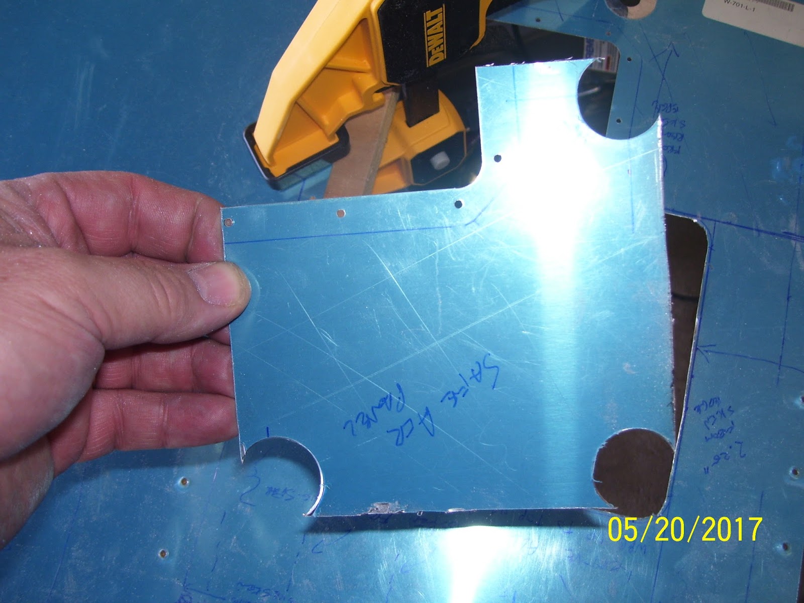
After reading the instructions that came with the SafeAir access panel kit, I decided to start with cutting the new opening for the new access panel. they give two measurements that I think I have already mentioned - 6 inches and 2.25 inches, to locate the new panel.I measured and then drew the outline on the Le skin.then I had to determine what radius was used to create the new panel, because it was obvious from looking at it that it was not the usual 1/8 or 1/4 inch radius, and was much bigger. After some creative measuring with a plastic hole template that I bought from a school supply aisle at the store a long time ago, I determined that the radius was 1/2 inch.

This then meant that I needed to buy a new unibit (step drill) from HF aircraft supply that had a 1 inch diameter step, as none of the ones that I currently owned were that large. Before I could drill the 1 inch holes in the Le skin I had to measure the radius of .5 inches by measuring that distance along the straight edge on either side of each corner. Where the lines cross is .5 inches. then I decided to place the pilot hole just a bit outside of that mark, because you need to leave some excess material and file your way down the final fit to ensure that the access panel fits nicely into the opening. This next pic shows the .5 inch marks and the #40 pilot holes I drilled:


The next reality was that in order to drill the necessary 1 inch holes with the new unibit, I would have to be able to raise up the skin by just over 1.5 inches to allow enough clearance for the drill bit. So I took some 2x8 pieces of wood that I use to level my trailer tires when I camp, and some spare wood that I still had from when I cut the LE rib templates for bending the subskin, and I placed them on my work table. Then I tool a 3/4 inch thick and very long drill board that I had not used in a very long time, and placed it on top of the 2x's, giving me plenty of clearance for the drill bit. I also needed to make sure that the wood was placed directly under the wood to keep the unibit from severely marring the metal.

I mounted the bottom of the LE skin on the drill boards and clamped everything down. Here was the first hole, all drilled using my cordless electric drill. I went slowly and took time to clear debris from the hole to allow the drill bit to continue cutting. In the next pic you can see how much excess material I left between the edge of he hole and the traced panel line around the corner (about 1/16th of an inch or slightly more). Having gone through the entire procedure now, in hindsight I would have left less material to remove around the edges, because it took a lot of filing, sanding, and smoothing to get the fit just right for the panel. But at least you can definitely verify that this was definitely using a .5 inch radius:


Here is the clamping arrangement of the table and drill boards:


I had to adjust the LE skin a bit for the third hole due to the width of the 2x8 not being quite wide enough to drill all three holes. After that was done, I ended up with three pretty uniform holes:


Then came the cutting of the rest of the metal. I used my Dremel tool with a flex shaft extention and an EZ lock cutoff wheel. These have seemed to serve me pretty well in the past, and this time as no different. This is always nerve racking, however, because it is very easy for these 30,000 RPM cutting wheels to decide to grab the metal and completely destroy whatever you are trying to cut in a matter of split seconds. SO I mounted the actual Dremel tool on the shaft of one of my clamps that I intentionally mounted independently on the work table, so I could use both hands to control the flex shaft and the cutting wheel. this actually went fairly well.

Prepping for the cut. It tool several episodes of clamping, cutting, repositioning, and reclamping to put the metal in just the right spot to cut each of the 3 sides. Sometimes you just have to get creative and use whatever is around:


After cut number 1:


The goal is always to cut away from the line a bit to ensure you don't mess up the cut. IN this case the task was to remain inside the lines of the panel.

Repositioning and reclamping for the next cut:


And after the second cut:


And after the third and final cut. Normally there would have been 4 cuts, but since the existing hole was already there, only 3 cuts were needed:


Next came the task of slowly filing away the remaining material up to the lines drawn around the panel. I used a normal, fine tooth, straight flat file, and even my cut off wheel in a rather unique fashion that I have never tried before, to trim the corners and the straight edges as much as possible. Then I resorted to a 1/4 inch sanding drum with the Dremel tool to perfect the corner areas, and to blend them with the straight edges. A word to the wise - be very careful using the straight file, as it is very easy to create a ridge of metal or to cut too deeply if you are not paying attention. this is always an exercise in patience and in removing very small amounts of material and constantly checking the result to make sure you do not over-do it. I almost made that mistake with the cutoff wheel in one of the corners, but I think I averted the problem after smoothing the corner with the sanding drum. This next pic shows I am getting close but not quite there yet.


After finally getting the fit to be acceptable to me, It was time to fit the mounting flange for the panel by clecoing the panel to the flange in an upside down manner and using the panel to center the flange so that the flange mounting holes can be drilled into the skin. I have not had to deal with this sort of thing ever since I made my first flange in the Sport Air sheet metal class that I attended many years ago.  So everything was an adventure into the unknown. As long as you do a good job cutting out the access panel opening in the skin, the flange should line up exactly like it is supposed to. Mine was not totally perfectly aligned, but it was close enough for me.

I had to readjust my table setup again to allow a gap between the edges of the skin and the new access panel opening to allow room for clecoes to be inserted without interference from the wood underneath. Here is how I setup for that:


Once the panel is centered in the new access hole, I used a couple of cleco clamps to hold the flange in place and then started to drill the #40 rivet holes through the flange and the LE skin. Only the outer holes are drilled as these are the mounting holes that attach the flange to the skin. the other holes are for the nut plates that the panel will screw into. The larger holes are predrilled in both the panel and the flange to #30, and the panel is attached by some #30 clecoes to the flange.

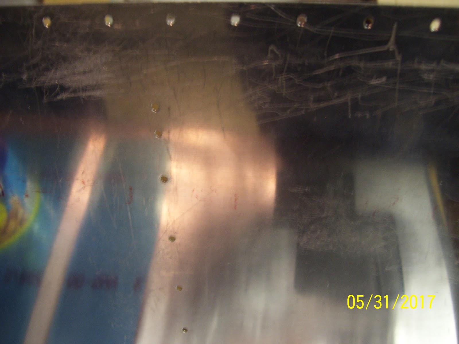
I could not drill 5 of the holes as these are the ones that overlap the existing hole that I will need to fill in after this lovely task is completed. Here are the clecoes in the holes that I WAS able to match drill:


And finally, from the back side of the LE skin, it is a bit hard to tell from the pic, but I think that the fit of the panel looks even better than I thought it did. When this is finished, the flange will be mounted on this side, and the panel will be on the other side (reverse of what is shown now).


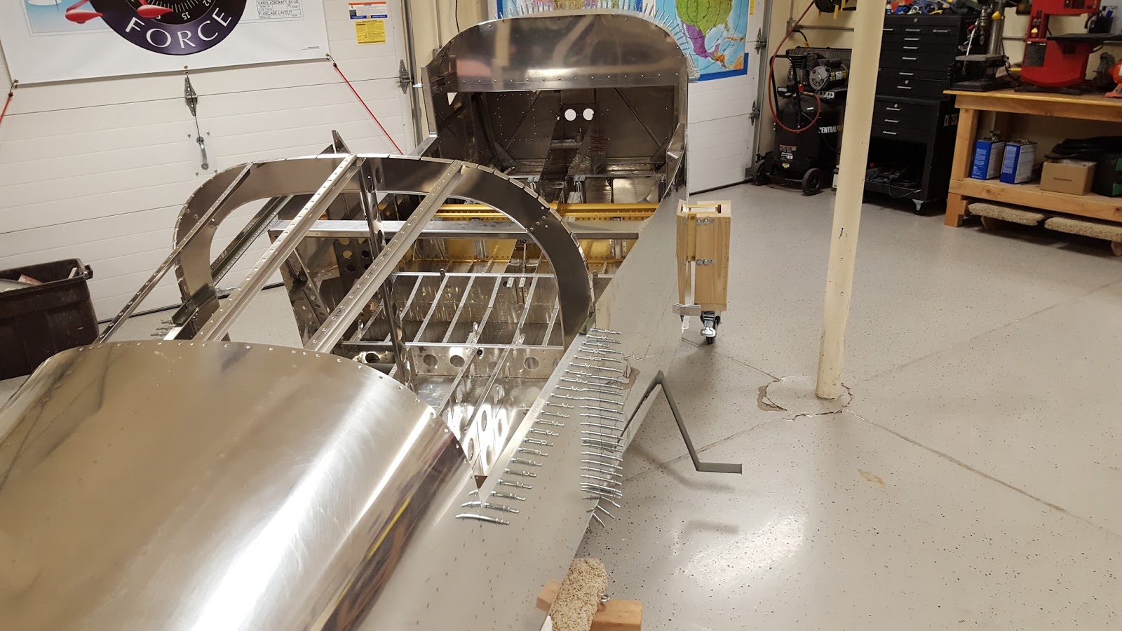
My next steps are to mount the LE back onto the wing spar for the 10 millionth time and reattach the subskin. I still have to decide if I want to trim the subskin away in these areas for the panels, or if I want to use the subskin as the mounting flange.for the panels. This would be relatively easy enough to do now that the flange mounting holes have been drilled into the LE skin. All I have to do is match drill them again into the subskin once it is mounted in place to the LE.

I have to figure all this out to determine how to trim the subskin to its final form. I also need to drill the rear rib flange to wing spar holes in the newly modified 408 rib. Then I will have to remove it yet again to debur the holes. This process just seems like it will never end, but at least I am making progress, regardless of how slow it might be.

Sunday, May 14, 2017

Prep for new SafeAir Access Panel

Not too much done on the plane today due to Mother's Day and extensive yard work. I made preparations for cutting the new access panel opening in the bottom of the left wing LE outboard skin. Took the following steps:

Measured location and traced the outline of the new panel per instructions from SafeAir. The measurements are 2.25 inches from the edge of the LE skin where it butts up against the fuel tank skin, and 6 inches from the rear edge of the LE skin (the part that attaches to the wing spar.) This is where one corner of the panel is located.

Determined that the diameter of each nicely curved corner of the new panel is 1 inch, so the radius is .5 inches. This is a rather large radius for a piece of metal, and is much larger than the radius of the corners on the Vans panel.

Measured and marked 3 of the 4 corners of the new panel with the .5 inch radius. I could not mark the 4th corner radius because that space is already missing on the LE skin due to the pre-cut panel hole for the Vans panel.

I'll have to come up with a way to cut a 1 inch hole in the skin to match the radius of each corner of the new panel. I don't have a wide-enough unibit with a 1 inch section on it, so I may need to go buy one. Don't want to use a hole saw on this aluminum, especially not the LE skin for fear of damaging it. Might be able to use a flat blade one inch hole cutter/drill bit, but will need to practice on something before I commit to that. I think that a one inch hole is too small for my flying wheel cutter that I have yet to use on anything.

The 1 inch holes need to be drilled in each corner of the skin to serve as starter holes for cutting out the square pattern for the new access panel cutout pattern. They also serve to bring the cut line very close to, but not quite directly on the corners of the panel cutout. This allows one to cut the panel space so that it is close enough to the drawn edges of the pattern so that they can be filed to the final fit for the new access panel. You need to creep up on the final lines for the access panel so that it has the proper seamless fit on all edges and corners. Otherwise it looks ugly and causes drag if there are any gaps between the skin and the panel cover.

Next steps:

Will probably need to remove all the other ribs from the LE skin and clamp the skin down on a drill board so that the unibit holes can be drilled cleanly. The area of the skin to drilled needs to be flat against the drill board, and the only way I can do that is to remove the other ribs.

Use my center punch to mark the center of each hole to be drilled by whatever drilling method I come up with.

Drill each corner hole in the LE skin.

Use a cutting wheel on the Dremel tool to remove the rest of the pattern from the LE skin.

Note that doing this will leave this area looking like a bit of a mess, with part of the new panel hole overlapping the existing hole from the other panel, which will eventually need to be covered back up. That will be remedied later.

File the edges until the new panel fits perfectly in the new panel hole in the LE skin.

Proceed with the rest of the SafeAir instructions for fitting the new attachment flange for the new panel cover. Somewhere during this step I have to figure out how to cover up the old panel hole while retro fitting a way for the subskin to act as the mounting flange for the new panel. There's lots of geometry involved here, as well as figuring out where to drill rivet holes for old panel, and how to design the subskin to act as the mounting flange for both panels.

Confusing? It is to me too. So I have to go slow here to make sure I don't mess this skin up so bad that I will need to order a new one.

KPR...

Thursday, May 11, 2017

Update on 6 year old Akzo Nobel Primer and on to the next LE Challenge

I am happy to report that the 6 year old Akzo Nobel primer that I used the other day to prime several parts, including two of the LE ribs, seems to have worked just fine. There is no flaking or chipping, and adhesion to the metal seems to be just fine. So I think I can continue to use that $200.00 investment until it runs out. Good to know.

Now for the next challenge. As I previously reported, I can still remount the LE again and final drill the two rear rib flange holes, but before I do that I wanted to start the process of trimming down the subskin to its final form. I had this pretty much figured out until I encountered the next challenge:

What to do about the existing service hole that was pre-cut from the factory on the bottom of the left wing LE. the right side does not have this cut, and that is because the original plans located this hole for installing and servicing the stall warning kit. To further complicate matters, the access panel that is designed by SafeAir for allowing installation and access to the auxiliary fuel tank transfer pump is located in a slightly different location. Part of this location overlaps the location of the existing hole that Vans already cut into the skin. Each of these access areas requires installation of a backing plate/stiffener to serve as a mounting flange for each in inspection plate. Here is the pic that kind of lays this all out:


The unfinished parts are the access panel and mounting flange from the SafeAir kit, and the blue colored flange and access panel that overlaps the SafeAir panel are the ones from Vans. Almost immediately you can see the problems. The Vans access panel is more to the rear of the skin, closer to the wing spar. The SafeAir location is more forward (the flange is not in the correct location, which is where the unfinished cover plate is. I just wanted to separate them so that you can see that they are two separate parts. You can also see the size difference.

Since I decided not to use the Vans stall warning system, opting for an AOA solution instead, I would really rather use the SafeAir kit. But how do I get rid of the existing hole that Vans made, and then re-cut a new one to fit the  SafeAir kit? As you can see, I will have to cut out part of the existing hole, but not all of it.

To complicate matters even further, my subskin currently resides where either of these mounting flanges would need to be installed. This may actually turn out to be a blessing because I may be able to  use the existing subskin as the mounting flange for the new panel, and it will also serve as the mounting flange for the existing panel that will need to be permanently mounted, except for that small area that overlaps the hole for the panel of the SafeAir kit. Then there is the fact that the skin thickness of the SafeAir panels is thicker than the .025 LE skins.My caliper shows them to be about .0315 inches thick. My guess is that they were cut this way because this kit is designed for several different Vans aircraft models, including the RV-10, so they may be thicker because of that.

I purchased the Safe Air panels because even if I choose not to install their aux tanks right away, it will be nice to have these panels already installed, in addition to the bung kit on the fuel tank, so that all I will really need to deal with is the actual installation of the aux tanks and the transfer pump, and the hose fittings between the main and the aux fuel tanks and the transfer pump. So the more I do now the less work I have to do later.

Not only that, but I like the larger, and more centrally placed location of the SafeAir panel. A long time ago I tried to fit my arm and hand inside the smaller panel that Vans provides, and there just isn't much room for either. I could imagine having a very difficult time troubleshooting fuel leaks in this area or servicing the transfer pump.

So basically, I need to cover up the current hole and cut a new hole. I'll have to think on this one a bit to get the sequence of the steps down correctly, but I think I can do this smartly by using the subskin for the mounting flanges. Luckily, the right LE skin does not have this mess of an existing access hole, so all I have to do on that side is cut the hole for the SafeAir panel in the bottom of the right wing LE skin.

Did I mention that I will be glad when all the LE work is done, so that I can start on the fuel tanks again..... It just never ends. Whhhhhaaaattt????? Did I just admit that I am looking forward to working on my fuel tanks??? I must be crazy.

KPR.

Tuesday, May 9, 2017

Pounded 12 Rivets Tonight

OK, so I squeezed instead  of pounded them. Whatever method it takes to set them successfully matters not. These were the rivets to attach each of the two flange extensions to rear rib flange - 6 per side.

I tried to do all the right things - drill some practice holes, select the proper length rivet, study the best clamping/securing/riveting method, including positioning of the pneumatic squeezer for each rivet, cleco positioning, and a hole host of other things. I had t check the operation of my squeezer since I had not used it for a very long time. It seemed to function just fine.

I cut a small piece of .032 aluminum and already had another piece available to use for testing. The total thickness of the parts is .064, which is the same for the flanges and the rib. An AN470AD4-4 dome headed rivet appeared to the the correct size and length according to my rivet gauge. I match drilled 3 holes and then started out with my manual rivet squeezer just to check the depth settings on the rivet before mashed them with the pneumatic riveter. They appeared to be set properly:


Here is the riveter with the cup set on top and the flat set on the adjuster on the bottom.


Now for the challenging part. First, these parts are small, and there are a lot of rivets spaced very close together. At least 5-6 rivets were required in accordance with AC 43.13 procedures. This makes clecoing and riveting a bit of a challenge, because clecos are much wider than a rivet  hole, and it  makes it much more difficult to position the squeezer. You have to get creative about clamping the work and clecoing the parts on both sides. Here was my setup:


And this next shot gives you an idea of the positioning of the squeezer, which had to be changed from hole to hole, and then again when the part was flipped over to attach the flange on the other side.


It turns out that I should have applied some reverse clamping and support. The rivet sets were positioned so that I could apply some force against the smaller part and the manufactured dome head of the rivet to ensure that the parts would not separate from each other.The problem is that while pulling against the manufactured head of the rivet, the rib was allowed to bend just a bit, and this may have contributed to some less than perfect shop heads for some of the rivets. I did my best to flatten some of them out afterward, but I think they are good enough for this particular application. Here are the results:


Wow! Two years just to make a W408 rear rib flange look like the W709 rib that it is replacing. Now that this is done, the next step is to reassemble and reattach the entire LE to the wing yet again. Now that the flanges are attached to the rib, I need to drill two more holes, one in each flange, by match drilling the new holes from the existing holes in the rear of the wing spar. Once this is done I can finally start working on cutting the subskin to size and prepping the other ribs.

One small step for me, one less step to do..... and so it goes. (Astronaut humor).

KPR.

Monday, May 8, 2017

Prepped and Primed the Modified LE 408 Rib and Planning for the Upcoming Fiberglass Work

Never thought I would actually get to the point where I am ready to spray primer again.

Prior to getting to this point, in the week since my last post, I have been very busy reviewing my fiberglass materials and instructions from the practice kit as well as my old information from the Composite Sport Air work shop I attended a few years ago. I found myself deeply immersed in the details of the original reason I started on this LE mod a long time ago - to be able to select and change out different leading edge platforms - one of those being a formed leading edge with LE light simulated machine ports that I can connect to the electrical system and mount to my leading edge to have a little simulated gun fun.

There is a lot of fiberglass work involved that will utilize a number of different materials. the real challenging part (yes I haven't even got to that point yet), is creating the removable leading edge that will attach to the subskin that I have been working on for so long now. I will either be making this detachable LE from metal or from fiberglass, and I will be making a separate mock up to test out which method may be best.Anyway, lots of research and reviewing previous posts and information have taken place over the past week.

As it turns out, I also needed to do some review and research and relearning of how to prime. I had to review and relearn everything from the setup, prep, execution and cleanup. The main focus was on the two small 90 degree rear flange extensions that need to be riveted to the modified 408 rib. The rib itself also needed to be primed before I could rivet the extensions on. Since this seemed like a small amount of metal to prime, even for my 7 ounce touch up gun, I decided to prep the normal 408 rib as well, and also the original W423 joiner strap for the left wing.

The other part of this adventure was trying to determine if my Akzo Nobel 2 part epoxy primer was still any good or not, since I first obtained this stuff from Aircraft Spruce back in 2012 at about this same time (May). This stuff is supposed to have a very specific shelf life that has long since expired, so this was to be an experiment to see if the primer is still good or not.

So all I needed was my smaller touch up spray gun from Harbor Freight. It has a 7 ounce cup but normally holds 5.25 ounces of fluid. Akzo Nobel epoxy primer is mixed at a one-to-one ration and then must set for .5 hours before it is ready to use. These next couple of shots show everything that needed to be set up to prime.The list includes:

Card Table
Newspaper
rubber gloves
wood paint mixer
mixing cup
paper filter
spray gun
method to hold the gun steady on the table (I used the tea pot from my trailer)
Both parts of the primer (each part comes in a 1 gallon can)
paint shaker
Plastic Turkey Basters (one for each part of the primer)
Post It Easle for testing spray patterns and flow
Acetone
microfiber cloth
paper towels
respirator
Safety goggles
Small sized priming fixture with chicken wire for supporting the parts


Turkey Basters? What on earth are those for? Well that became another experiment. In the past I had a hard time getting the material in the one gallon cans into the small mixing containers that I use from NAPA auto parts, and this led to very big messy, smelly mess during one session. SO I wanted to find a way to be able to extract smaller amounts of material from each one gallon can without having to pour it out of the can. All these plastic paint can doodads just don't seem to work well for me, and I wanted a better, safer, cleaner solution. SO I went looking for a metal turkey baster - never found one. But I did find some plastic ones. I knew that they would allow me to cleanly take the amount of material from each can and place it in the mixing cup, but I was not sure if the plastic would met away when dipped into each can, or if it would contaminate the primer somehow. Decided to give it a try and see what happens.

Here is the result after using each one. Prior to dipping them in the can, they were both clear. In the next pic you can see how the plastic has in fact crazed just a bit, but for the short time that I needed them to get the right amount into the cup, they seemed to do the job that I needed. Made for a much cleaner mixing session:


For smaller sessions not requiring very much primer, I love using the 1/2 pint mixing cups from NAPA auto parts in this next picture. After mixing all this volatile carsenigenistic stuff, the basters and the cups all go into the trash.


And here is the primer. Pigment comes in one can and the hardener comes in the other one:


Notice the mix date going all the way back to 2011. This stuff was made in 2011, was sold to me in 2012, I believe a month before the date in which it was to expire if I recall correctly. Then it has sat on my garage floor in hot summers and extremely cold winters, and has not been used in well over 2 years. SO yes, this was going to be a grand experiment indeed. I figured that if it did not perform as expected I could remove it from the metal and order some new stuff. At 200.00 a pop, it was worth a try to see if this stuff was still any good.

Next up is my jury-rigged solution for keeping the spray gun upright after everything was mixed and poured into the cup for the gun. the instructions say to keep the gun level after the cup is attached to avoid getting material in place in the gun where it should not flow. I don't any sort of hangar for this gun, and when I also added a Harbor Freight air regulator to the gun, it made it even more unstable. So I decided to try the tea pot from my trailer, which I had removed while it is being serviced in preparation for the upcoming 2017 Airventure in Oshkosh. While not perfect, it did the job:


And finally, here is the Post it easel sheet that I use to test the pattern and flow before I use it on each part. I have to open the flow valve on this gun all the way to get the flow that I need, and I try to keep the pattern to about 4-6 inches per pass.


And here are the parts after priming. Best I can tell, the primer seemed to mix and lay down exactly as I remember it from before. The parts all look OK, but they are still drying due to increased humidity and rain storms that hit the area right at the same time I was ready to prime (figures). I will check them tomorrow to see if the primer looks OK. If it does then I will be smashing some rivets on the modified rib tomorrow night. Haven't done that in a while either.


All total, it took me about 2 hours to review instructions and get familiar with the spray gun again, an hour to set everything up, .5 hours to spray the parts, and .5 hours to clean everything up. I was glad that I was able to keep everything clean, and that the primer and the mixing all seemed to work as expected.

KPR....

Monday, May 1, 2017

2 Halves Make 1 Whole RV10 Fuselage

Throughout my experience with building an experimental airplane I have been fortunate to come to know many individuals that share the same passion. Through those relationships I have been able to witness and participate in many unique and exciting things. Yesterday I was able to add one more to that list by helping my buddy Mike join both halves of his RV-10 fuselage together.That airplane is so large (Seats 4 people plus a lot of bags) that the fuselage is initially built in two separate sections. Each of these is then joined together at the appropriate time.

This joining together of major airframe parts is something that has always fascinated me. Being a WW II aviation history buff, I am always intrigued when I see film footage of the factories that were creating fighters and bombers in an assembly line. Large overhead cranes and straps with fuselages and wings suspended from them would somehow be guided into place by a handful of humans, and then they would be magically joined together. I guess this fascinates me even more right now, after having been exposed to airplane building techniques, many of which were developed and perfected way back during WW II.

Three of us - Mike, myself, and Jon Banks were all that were needed to complete this tasks. The process we used at Mike's did not require any cranes or heavy weight-bearing straps, but was still just as challenging and fascinating to see it all happen. Mike's tailcone was strapped down on a 4-wheeled flat dolly shown below:


Before we began the joining process the forward section was up on several saw horses. Mike had   Built two very interesting dollies for the forward section. They basically looked like two miniaturized sets of landing gear bolted to the center section wing spar flanges. Jon and I both made fun of these rather interesting sets of wheels, but turns out that they more-than served their intended purpose. The first step was to get the forward section off of the saw horses and onto the ground.


The rear of the forward section was temporarily sitting on the two steps that will be utilized by pilot and passenger to enter the cabin of the airplane. I am dubbing the above pic the "midget 10." With that done, the next step was to maneuver both sections and begin the process of aligning them at the proper angles so they could be joined together and secured.

The trick to this turned out to be setting both sections at the proper angle so that all the mating surfaces of both sections would line up correctly. How was done, you might ask? Measuring sophisticated complex angles, or lifting both sections  a prescribed amount? Well, it turns out that several pieces of 2 inch thick foam under the rear section, and some boxes full of books were used on the front section to get both pieces at approximately the right angle so they could be joined together.

This task was not easily done in one shot. It took several attempts at adjusting the foam and the boxes either forward or back from their current positions, and then eyeballing the angles and alignment of the mating surfaces of both parts. Then the metal had to be aligned and positioned correctly while the front section was locked into place and the tail was  maneuvered forward and from side to side. It was further complicated by the fact that there were several different types of metal to join, and some of it needed to be sandwiched in between metal from the other part, while flanges from the bulkhead and various pieces of aluminum angle all had to be aligned as well. this took several attempts to get right. When we began, the left side aluminum was lining up, but the right side was not. Then one part would go in correctly and another would pop back out..... After messing with this for about 20 minutes, it all finally came together.

Then the task of inserting clecoes into the joined parts began. Getting ALL the rivet holes to line up enough to insert the clecoes was also a challenge for certain areas. Here is Mike with pliers in hand making it happen:


And here is Mike and Jon after the deed was accomplished. This is yet another major milestone in completing the airplane, so smiles are more than appropriate:


Not so easy to move things around anymore, is it?


Here is a pic that shows the final locations of the rear dolly, which has been moved up about halfway to serve as a support for a box that sits under the major support section of the bottom of the forward section and the location of the box being used to support the tail section. The combination of the rear dolly and the wheels mounted on the forward section gives just enough clearance to keep the foot steps off the ground and keeps both sections pretty well lined up.


And finally - Mike at the pilot's position with a makeshift seat in forward section of the cabin. I'm really jealous of this and I can hardly wait until that is me in my fuselage skeleton making airplane noises - a right of passage for builders that reach this important stage of the build.


Then, after all the hard work was done, Mike treated Jon and I to dinner. Thanks for that Mike! Now I can add this to my list of engine hanging and wing joining exercises I have been fortunate to be a part of. Not shown in these pics is the very large top fiberglass section that also joins the two halves together on the upper portion of the fuselage. I imagine Mike will be starting on that work in the not-too-distant future. Lookin' good Mike!