Thursday, June 30, 2011

Practice is over, time for the rudder roll

Here are some dimensions I used to cut the slots and drill the hole for the J bolt. I used a 1/4 inch clearance from the edge of the skin to keep the J bolt and the pipe wrenches clear of the skin. Lots of measuring going on here....


Preparing the plywood table - J bolts and rudder in place


And a slightly better shot


Did I mention a lot of measuring? These slots are so close to each other because I had to cut a different slot for the bottom section of the rudder. The distances between the middle adn top section are not quite the same as the bottom and the middle, so you have to make adjustments of you plan to do one section at a time, which I highly recommend.


Preparing to tape up the bottom section


All taped up and J bolts in place


and the other end....


and this shows the clearance from the edge of the skin...


Next shows the J bolt detail and how much I cut off. Make sure that the J bolt is high enough to clear the skin, and long enough to force the bar to stay in place.


Left side rolled. I actually rolled the top and middle sections at the same time since my pipe was long enough to do that, and then I rolled the bottom separately. Many people report that trying to do all three at once it quite difficult, since it takes a fair amount of force to bend that much aluminum at once. Better safe then sorry, so I chose to do separate sections. As you can see I am way short of the mid point, and I am frustrated at how much more work this appears that it will take to get these holes to line up so they can be riveted so I can finally be done with this assembly. The rudder is a lot of work, but if you just keep working on small portions of the assembly at a time, it will get done.


Next is something I overlooked yet again. More primer (yuck!) Thanks to Steve Riffe and a thread on VAF, I found another rudder pic from him that showed the primer applied to the outside surface of the underlying skin. This is an important thing to do since the outer skin will lay on top of this one, and once riveted will have to endure all sorts of vertical weather phenomenon, such as rain, snow, etc. Failure to prime or protect these critical areas may result in corrosion and the need to build a new rudder (double yuck). So, I ahve masked the outside edge of the underlying skin (the skin I just rolled), and will prime that edge tomorrow. Then I will proceed with the rolling of the other side of the skin, and then try to figure out how to force the edges to get close enough together to allow clecoes to be inserted in the holes, followed by pop rivets.... Hopefully I can call the rudder finished by this weekend, and then it will be on to the right elevator assembly.


Time for bed... To be continued as always....

Wednesday, June 29, 2011

298 hours on the hobbs. Rolling, rolling, rolling.........

Well, I wish I could say I was rolling. Maybe "rolling around in it" would be more appropriate....So I enlisted help from my oldest son and my neighbor, Kevin Shepard, whom I work with, and whom is also a CFII and fellow pilot, to help roll the leading edge of the rudder. The next series of pics will show my implementation of Dan Horton's solution to rolling the leading edges, and the result after performing the roll, and the ongoing dillema of trying to figure out how to get the correct dimensions to close up the leading edge without creasing the skin right next to the forward spar.

The problem is that regardless of what circumfrance bar you use as a form for the roll, you are still left with about a 1/2 inch gap in the middle and bottom sections that has to be closed off somehow. Vans instructions oin the manual even state that the roll is just a starting point, and that most people finish it by hand to get it to final form.

Anyway here are the pics:
The goal is to create a straight, consistent roll of the skin. Dan Horton basically found a no fuss, no muss way to do this, with a little preparation and careful attention to detail. This step was new and scary enough for me to take the time to create a mockup of the real thing by using a small piece of plywood adn a piece of .032 aluminum sheet from HD, which was about 18 inches long and about 10 inches wide. I cut slots and drilled holes in the board as shown, and cut slots in the aluminum to match the pearing access cutouts of the rudder skin. I used 10 inch pipe wrenches to perform the roll after the bar was all taped up with Gorilla tape. Other than some careful measuring, the only other fabrication that is needed is to turn some U bolts into J bolts by using the dremel tool to cut one side of the threads so that there is just enough of a hook to fit over the bar. You tape the bar to the aluminum, then place the ends of the bar under the j bolts, and then secure the J bolts with nuts on the bottom of the plywood. Tighten them down just enough to allow the bar to roll freely, but keep the aluminum flat on the surface of the plywood without lifting up. The action when you roll is a downward and outward movement to ensure that the skin does lift up. Others try to do this freehand and end up with less than desireable results, whereas this method using the bolts prevents the skin from lifting at all.


Next is the j bolt in place over the bar, with the skin all taped up. There is a method to the tape - 4 pieces, starting with 1/3rd on the skin, 2/3rds on the bar, then the next piece is 2/3rds on the skin, adn 1/3rd on the bar, then the last two pieces are placed at 50/50 on the bar and the skin. The mystery element to this is exactly where to place the bar in relation to the edge of the skin. I chose to place mine just past the tangent point on the bar, so that the general form of the edge of the skin wold still be somewhat curved, and not totally straight.


Shows the 1/4 inch hole I drilled to insert the J bolt, and the slot that I cut out to allow access for the pipe wrench to swing through about 180 degrees for the bend. There is always some degree of spring back. How much of this you experience is typically due to the force applied during the bend, combined with the amount of travel. Also shown is the fully taped skin to the bar. The bar I used is 1 inch water pipe. After using the same bar on the rudder, I would suggest using 1/2 inch or 3/4 inch diameter material for the bend. Mine are just a bit too fat, adn will require a lot of post-bend massaging of the skin to get the bend down to the correct dimension. I think a smaller diameter will work better to get the skin a bit closer to the needed dimension. You have to measure the location of the hole for the J bolt so that it will not be in the way of the skin as it is rolled, and then you have to cut slots that align with the ends of the pipe, and of course the pipe needs to be the right length.  


Next is removing the tape after the bend was completed. Notice the difference in the bend on the other side compared to the one I did on this side. Just shows you how different they can turn out depending on numerous factors.


And finally a shot of both practice bends....


One final piece of this process I left out earlier, you need to cut a sheet of plastic to prevent the skin from scratching on the wood while it is being rolled. the act of rolling the taped skin while secured to the wood by both J bolts cause the remaining skin to move forward. Thus the reason for the pastic. I just happened to have some lanscape plastic laying around so I used that.


And now on to the real thing. First, here are the U bolts that I purchased. I used 3/4 inch plywood remnant from the shelves that built for the garage way back when I was preparing the shop for the build.  This dimension works out quite well for 1 inch radius water pipe. If you can find the right radius for smaller sized pipe then use that. 3 inch long bolts are way too long, but you can cut them to suit your needs no problem with a dremel cutoff wheel.


Thursday, June 23, 2011

Finishing Rivets and Preparing to Roll the Leading Edge of the Rudder Skins

Before you can start riveting the skin, you need to place a small dab of RTV sealant where the two stiffeners meet at the rear of the rudder. You know, that now impossible small space at the back of the rudder where you can't hardly do anything! Luckily, my wife works at hospital. After asking the right people, she was allowed to bring home several sizes of dosage seringes. These make the job of putting the sealant in the right place much much easier. You take the RTV from the tube, squeeze it into the seringe, and get it as close to the stiffener joint as possible, and squeeze away. You are trying to coat the very ends of each stiffener, as well as the last rivet that is set on each one, to prevent cracks from forming in the skin in this area due to vibration.

The RTV and seringe that I used:

And here is the RTV after using the seringe to put the RTV on the stiffeners:

Here is the flat sets that I used in the squeezer to set the flush rivets on the skin

I ground down the edges on the flange yoke similar to the way I did this for the other yoke. I also did it for the no hole thin nose yoke. Finally I have a set of yokes that should no longer mar up the surface of anything.

And now to set the remaining rivets on the R710 support bracket on the bottom of the rudder. Again, most folks use the pop rivets here, but IO felt up to the challenge to try to figure out a way to set these holes with the usual hard AN426 flush rivets used to attach the skin to the frame.


Step 1: Re-mount the rudder against the bench with the bottom side up so that I could access the holes in the bracket. This was quite the imaginative process, trying to figure how to secure everything correctly, without damaging the rudder. Solution was to basically take a long piece of particle board that has been my trusty drill board up to this point, set it along side the work bench, and proceed with clamping the rudder skin to it as shown in the photos:


And now we can start riveting the remaining 6 rivets on the sides of the support bracket. What I did was:
1. Used the fat man bucking bar which is short enough to fit inside the access hole of the bracket, setting it on a piece of the underlayment foam that I recently used to install my hard wod floors in the house, and slid it up into position for the forward-most rivets on both sides. I held it in place against the rivet with one hand, while holding the rivet gun with the other, adn I was able to successfully set the two forward rivets. Then I was able to use the hand squeezer with the flange yoke to set the remaining 4 rivets.

When I finished, all of the rivets on the side of the bracket were nicely set with normal hard rivets. Again, having the correct yoke and rivet sets, and a bucking bar of the correct size, allowed me to accomplish this with relatively little fuss.

Tuesday, June 21, 2011

292 hours on the hobbs Final Riveting and Skin Preparation for Rudder

So it's been a few days since my last post, but I ahve been busy on the rudder. I am beginning to wonder if this part will ever get finished. Lots of tricky riveting to do. One of the other things that has to be done is to roll the leading edges once everything else is riveted together. Below is a pic of a controversial edge rolling tool from Cleaveland tools. I had ordered this with my tool kit and had done some practice pieces with it, but not with very promising results. Then I ran into a whole bunch of posts on VAF. I found one thread that clearly explained the problem. There is such a lack of guidance from the makers of these tools that nobody understands how to use them correctly. Even the hints for homebuilders video on the EAA web site does not show enough detail about how to properly use the tool.

As the pic shows, there is a large thin flange on the top roller. This fits right against the edge of the skin being rolled, and needs to stay in that position while rolling the tool. The other trick to using this tool correctly is NOT to set the depth between the rollers too close or tightly together. People think that you have to get this really tight on the skin to achieve the desired slight bend on the edge. In reality it just needs to be tight enough to allow the roller to EASILY roll along the edge of the skin. Everyone expects to see a noticeable bend in the edge of the skin, probably because the diagram in the picture in the plans provided by Vans shows this bend to fairly distinct. The fact is that the bend is barely visible to the naked eye when done correctly. The tool creases the edge of one side of the skin just enough to counter-act the tendency of the skin to curl up when the pop rivets are applied. Most builders are complaining about how they cannot move the rollers, or how wavy the skin edge turns out, or how uneven the rolled edge is because it slips away frome the edge while being rolled. ALl because they are not using the tool correctly.

The fact is, if you use it correctly, it leaves a nice, even, small crease in the skin, exactly like it is supposed to.

Here is a set screw to make certain that the depth of the rollers stays set exactly where they need to be


And the Top roller that shows the flange that is kept flush against the edge of the skin, adn also shows the tapered part of the roller that actually apples the bend to the edge of the skin....


A bad pic attempting to show the gap between the rollers after snugging them up against the skin so that they were firm but not tight or smashing the skin.

Another not so good pic trying to show the edge of the skin after rolling was completed. You can just make out a slight bend on the edge. Again, you only roll the skin edge that will overlap the other skin. You do NOT roll both edges.

Many more pics to post, but it's late, so I will finish catching up tomorrow. As a preview, I will post pics showing the method I used to set the remaining 6 rivets on the edges of the support bracket, putting RTV on the stiffeners before closing up the skin, and a mock up/test tool that I created for practicing the rolling/bending of the leading edge of the rudder...

Sunday, June 12, 2011

283 hours on the hobbs - Rudder almost completely riveted

I'll get more pics of this weekend's progress posted tomorrow. For now I will continue the previous post and show pics of the tip rib installation. Below is the setup that I used for just two rivets to attach the tip rib assembly to the top of the main rudder spar. I used the R717 straps that I fabricated for the bottom rudder as supports, and used my cleco clamps to hold it all in place.

I had originally set this up vertically in much the same way that I did to rivet most of the bottom rib assembly to the spar (see my previous post). Then I realized that this would NOT allow me to run the rivet gun and bucking bar the way that I wanted, so I switched gears, disassembled everything from the vertical support, and clamped everything to the smaller work table. This worked out MUCH better. The problem doing it the other way is that the rivets were not in a good position for me to access them properly with the rivet gun and the bucking bar. I need to have the rivet gun in my right hand and the bar in my left to rivet correctly. The manufactured rivet head in this case needs to be against the small flange of the spar in order to allow the gun and rivet set to apply pressure to the manufactured head of the rivet, which in turn pushes the parts closer together. I have had way too many other past experiences where I have NOT done this correctly, and I wanted to try very hard this time NOT to make the same mistakes.
I used my offset rivet set and the thin man tungsten bucking par to set these two rivets. Worked out beautifully. The spar flange is flush to the rib web, and there is no buckling or curling of the spar flange after driving the rivet.

A shot that shows the reason you need to use the offset rivet set. Shown is the main rudder spar on the bottom, and the rivet gun in position with the rivet head firmly seated in the rivet set(just out of frame on the left side), Notice how close the gun and set retaining spring are to the spar web. The offset, or slight bend and rebend of the shaft of the rivet set, allows for just enough clearance for the entire rivet gun to clear the parts.


And a shot of the other end that hows the rivet set firmly against the rivet head. You can just make out the separation line where the small spar flange butts up against the tip rib web. This is the correct process to set these rivets because it forces the two parts together when you apply pressure to the rivet set as I stated earlier.

With the frame all riveted together, it was time to cleco the skin to the frame and get this baby riveted. After a lot of squeezing, I only have about 8 rivets left to go, which include the 6 rivets on the sides of the R 710 support bracket on the bottom of the rudder, and the 2 bottom, most rearward rivets attaching the bottom rib to the skin. I intend to use standard flush rivets on these holes if I can work out my back rivet process correctly with a small enough custom bucking bar. If not, I will use the pop rivet alternative that is listed in the plans, as many other people do. More pics tomorrow! ALMOST THERE!


Saturday, June 11, 2011

268 hours on the hobbs. Rudder Frame Riveted

Man where to begin. there are so many little decisions involved in this process to properly get the Rudder frame riveted together correctly that I could write an entire book on the subject. I relied heavily on posts and kit logs from others to assist me. I guess I'll just caption the pics as best I can, since I took a ton of them to cover this process. As you all well know by now, I like the details - it is part of my "persona" that makes me who I am - different from everyone else. Alas, when it comes to finding additional info from others about the rudder final assembly, all Iam able to find are some generalized comments that usually only tell part of the story, and even fewer pics are shown that clearly cover some of the "gotcha" areas of this assembly.

So here is my attemp to alleviate some of that:
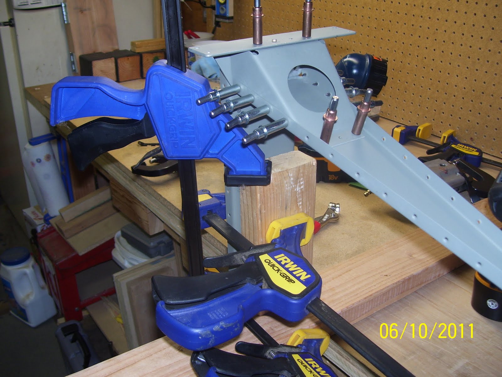
Step one - take the main spar and  - - what is my first rule of airplane building - - right - ALWAYS SECURE THE WORK! This is the main spar tipped upside down along side my work bench with the bottom rib and control horn already riveted in place.It also shows the R710 support bracket that is clecoed into place. I chose this configuration as the best method for securing the work since it gave me the best "all around visibility and access for setting the rivets in this complex area.

If you have smaller or more mobile work benches than mine, that will be a plus, because you will be able to move the work bench around to more easily position the work. Unfortunately, I had to figure out how to set things up without moving my benches all over the place, since mine are not so mobile. I basically took a spare 2x4 and screwed it down into my work bench, close to the pegboard, to provide a stiff support bracket for positioning the rudder frame. Then I used other combinations of wood to clamp the spar in place so that it would be rigid enough for riveting. You can never have enough clamps.


Tools - so what to use to set the structural rivets for the R710 support bracket? I chose the hand squeezer, a flange yoke, and both a half inch x 3/8 inch flat set and the 1/8 inch cup set for the AN470 rivets. Many posts indicated that the flange yoke and the 1/2 inch flat set are required for this assembly, and they are quite correct. The hand squeezer is lighter and allows more control than the pneumatic squeezer, and the longer flat set is needed because you need an extension to be able to reach the rivets that are inserted above and behind the big round hole in the support bracket.


This is where it gets interesting. A tip I learned from a VAF post a while back is that the rivet call out in the plans essentially provides the direction of insertion of the rivet. The manufactured head (in this case the round head of the rivet) will then be in the proper position against the proper part, and the rivet shaft will also be in the proper position for bucking the shop head. The general rule is to place the manufactured head against the thinner piece of metal, and set the shop head of the rivet against the thicker piece, to prevent curling or gapping the thinner metal. Otherwise, follow the plans.

So what I found in many different posts covering this assembly is that many people are putting the first four rivets with the manufactured heads out, or against the R710 bracket, but the ones that are following directions correctly by placing the round head underneath, so that the shop head is visible and can be easily checked to ensure that it was set correctly. So how then, you may ask, does one insert the rivet up underneath the bracket and into the hole? You cannot see the hole since it is hidden behind the bracket, so it is an entirely blind process. I found it "interesting" that nobody seems to comment about this. So, my solution, after thinking about it a bit, is shown below - I reverse-wrapped a piece of masking tape to the top of my finger (sticky side out) and then stuck the round head of the rivet on the tape as shown, I then I slid my finger into the large access hole in the bracket, and positioned the rivet until it could be pushed through the hole. Then I simply removed the tape. The rivet, although inserted upside down, still managed to stay in place rather nicely due to the close tolerance of the drilled hole and the rivet shaft.

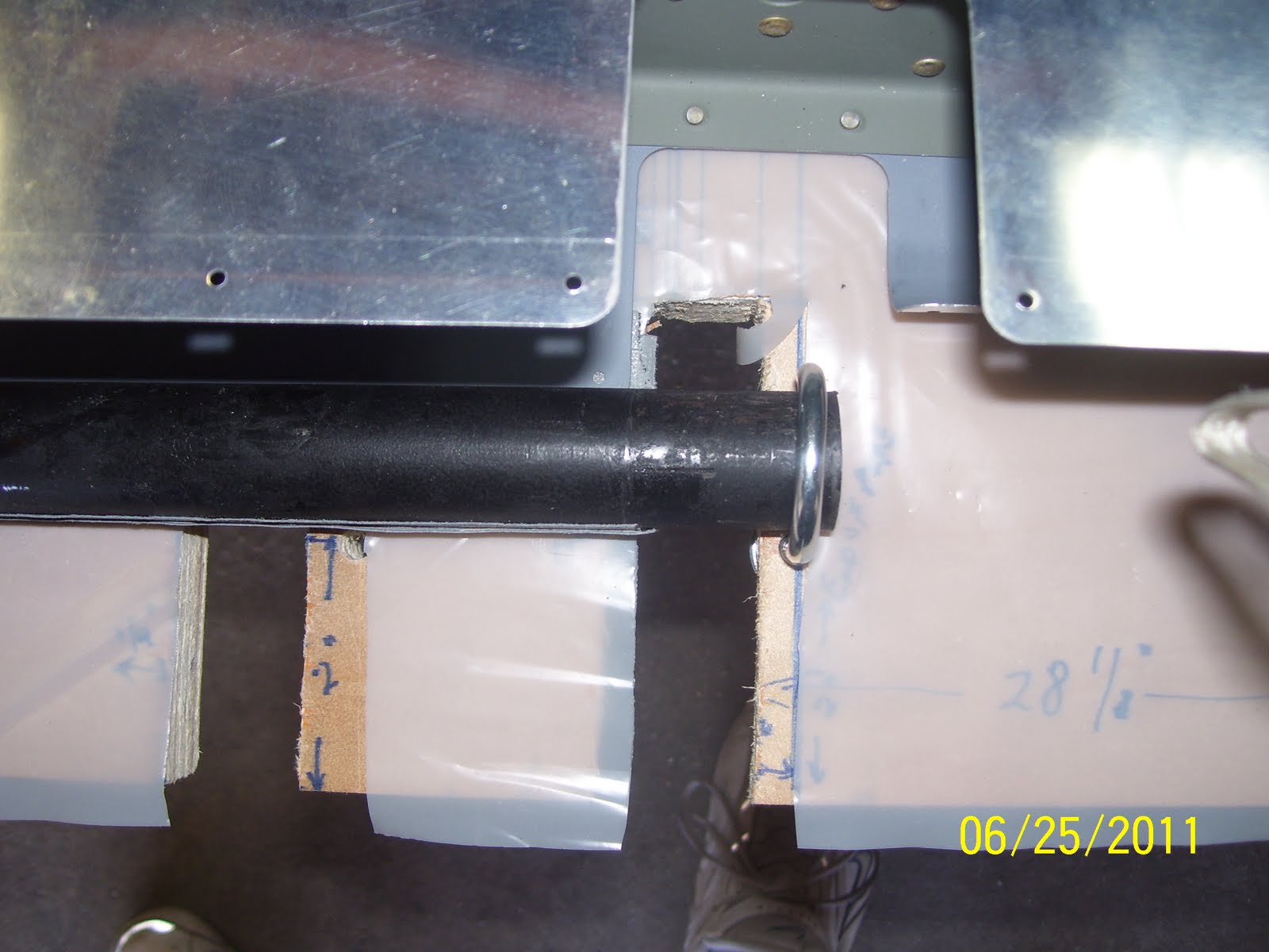
And here is the rivet after being inserted upside down into the hole. This, by the way follows the general rule mentioned previously (manufactured head is against the thinner metal) and also complies with the rivet callout in the plans from Vans. So all you other folks that are doing it differently - -you are doing it WRONG! Notice that I started with the two center rivets, setting them one at a time with the hand squeezer, which is another tricky procedure.......

Riveting in progress. This is  a similar pic to those from other builders in many other posts. What is not ever mentioned or shown is just how difficult it is to get the yoke into the proper position to insert it inside the support bracket, and then make certain that the cup set is sitting squarily on the round rivet head, which is all hidden from view. Several tips listed here to hopeflly benefit other builders that will visit this site...
1. Before inserting any rivets into the parts, setup your squeezer by taking a rivet and adjusting the set-depth to the correct level. You want at least enough depth to initially set the rivet to hold it in place, and not so much that you risk over driving the rivet. I always start small here and gradually increase the set depth after I see what is happening to the shop head of the rivet. I may do this 2 or three times until the rivet is correctly set.
2. remove the center clecoes, and when inserting the other end of the yoke into the hole, do it straight on from the center, but at an angle as necessary that follows the contour of the support bracket, if that makes sense. It is a tight fit regardless, but it can be done.
3. When squeezing, make certain that the flat set is positioned as close to the center of the rivet shaft as possible, and that the squeezer is held as straight up and down as possible, so that it is perpendicular to the surface being riveted. This will ensure that the cup set will slide into the correct position over the hidden round head of the rivet, even though you cannot see it. The access hole will provide just enough clearance to set the rivet without bending the bracket as the squeezer is actuated. 

If you do these 3 things, then the rivet will be set correctly on both ends. 

And this is me playing Airworthiness inspector with my little mirror so that I can peak up underneath the support bracket to inspect the round heads of the four rivets that I just set. That little mirror can be manipulated to inspect all sorts of things, especially when used by somebody that knows how to use it. I mainly wanted to see that all the underside rivet heads were sitting flush against the metal, and that they were not deformed in any way. All of them looked fantastic.


And here are the other three rivets on the back side of the bracket that attach to the rib. Much easier to get to and to set these rivets. Now that the structural rivets are set, only the flush rivets on both sides of the support bracket remain. These are not set until the skins are attached to the frame, so don't make that mistake either! Just remember to take your time through this entire process. Next I riveted the tip rib to the main spar.