Not too much to report this time. I received an order that I placed for some stuff from Vans, including the necessary LP-4-3 and 4-4 pop rivets that I plan to use for the majority of the Leading rivets that attach the rear flange of the LE ribs to the wing spar. I also ordered several #6 ring terminals and several feet of #18 wire so that I could practice crimping with my crimping tool, which I have not done since I took the Sport Air electrical class a long long time ago.
I needed to do this because the capacitive fuel sender kit requires you to put ring terminals on several pieces of wire that will be inside the fuel tank and screwed to each metal plate, and then to a BNC connector at the wing root that will connect to the other wire and connector coming from the fuel gauges and converter units in the fuselage. So I watched multiple videos from EAA and from SteinAir, and practiced crimping several terminals. I think they came out OK but I'm still not 100% satisfied with some of them. Continuity and resistance checks are all good, but some of the crimps don't look the way I think they should. Some combo the amount of stripped insulation and where I am placing the sleeve in the crimper I think.
I also ordered a small amount of Proseal just so I could play with that a little before I am ready to do the big job on the actual fuel tanks. I also ordered some rubber grommets that turned out to fit my .75 inch holes that I drilled in each wing rib for the black conduit to run my wires through. The problem is that the grommets only have a 1/4 inch opening in the middle, and I may want a bit more than that. At any rate, it was nice to have some to see how they install. I'm sure I'll have places where they will come in handy.
Some of the other stuff I ordered was the metal reinforcement kit for the horizontal stabilizer center section of the front spar, which was found to be prone to cracking in certain areas. I'll be installing this after I finish the wings while I wait for the fuselage so I can get it done. I may even decide to replace one or both of my stab skins, since that was the beginning of several "first time" blunders when trying to rivet my very first large skin.
I also ordered electronic copies of my RV-8 plans and instructions-something that Vans had made available for a while now but I never acquired. It makes it so much easier to to review everything without carrying around the big notebook.
Other than that, I managed to get outside tonight and final sand and clean the scuffed an filed areas of the skins for the scarf joint. Hopefully in the next day or two I will prime those areas and dimple the holes that still need to be dimpled, and then finally I can move on to bigger things with the LE again.
KPR
Monday, October 30, 2017
Tuesday, October 24, 2017
Scarfing the wing skins - more info
Wow. It's been a week and a half since my last post. In that time there has been a winter storm, large tree branches falling off the trees that threaten the roof of the house, severe winds, cold temps, and a lot of other things that I had to get done to meet other obligations that had nothing to do with work or with building the plane. I was way too over-extended last week, and I finally got a chance to recover a bit on Sunday. I was pretty much running on empty all last week.
I had to finish editing a video that I produced for my EAA chapter with footage that I shot at Oshkosh when B-29s FIFI and DOC flew together, making this the first time in 50 years that more than one flying B-29 flew in formation with other B-29s. Turned out pretty good - but as always video editing-doing it properly anyway - is an awful lot of work.
Then I promised to do a presentation for the meeting as well - so I had a double whammy for last Friday.
I finally had some time this evening to get back to the scarf joint. In between the last post and this one, I did some more research on VAF about this whole scarfing process. Turns out that, as usual, I should have done the research BEFORE I started the process when I mistakenly thought I had it all figured out.
NEWS FLASH for builders trying to scarf this joint with power tools. DON'T DO IT! I found a 3 page post on VAF with folks basically asking the same questions that I was. The basic advice was NOT to use power tools, as there is a risk of a sanding disc grabbing the skin and sliding away from the desired work area. TOO LATE FOR ME! I already did this on the outer surface of my inboard wing skin, you know - the part that everybody looks at on the top of the wing when your airplane sits on the ground. I took off too much metal over too wide an area. Now I am going to have to have an ugly primer patch on that section of the inboard skin. So, it's not too big of a deal since I plan to paint the plane anyway. But had I wanted to polish my airplane, this skin would probably need to be replaced.
So once again I have proven that for every step that I take where I do something that I have never done before, I manage to screw something up at least once. So my advice to anyone following this blog is frankly to follow somebody else's (Venting). Anyway, following the advice on this VAF post that I found, I drew lines on the inner and outer section of the skin where the joints overlap so that I would know what the borders are supposed to be. Then I took some electrical tape and placed it along side the marks to provide a sort of protective barrier for the next step.
Then you take a standard tooth vixen file and start tapering the skins using the hand held file - and NOT a power tool. Here is pretty good shot of what things looked like before I started to remove more material with the file:
 While this is hard to see, the fuel tank skin is on top, and the inner and outer top wing skins are on the bottom half of this pic. There is no longer a large triangular gap where the outer skin rides over the top of the inner skin, so that is progress. However, there is just enough of a ridge sticking up a bit higher than the fuel tanks skin edge, so it still needs more work. I was quite discouraged to read that some builders had managed to complete this whole task in about 15 minutes. Sucks to be me I guess.
Here is shot that shows the damage that a runaway sanding disk can do, as well as the sharpee line that I drew on one side of the skin. So I am overextended with my skin removal by about another 1.25 inches or so. I drew another line from the bottom side of the wing on bottom of the outer skin so that this line would also be present on the other skin when I separated them again.
 And here is the tape applied along each line on both skins
 Then you take the file and start systematically taking even amounts of metal off by running it across the area of the scarf joint on both skins

 You need to keep slightly angling the file so that it takes more material off at the upper corner of each skin, and thickens up the further away from the corner that you are. My original plan included using a small scotch brite wheel on my drill, but I used it for the wrong purpose. My plan was to use it to remove fine amounts of material, just like it does when you use it to debur the edges on various sheet metal parts. However, for this task, it does not do so well, because the wheel gets gunked up with aluminum as you run it over the flat skin. It is not meant for removing large quantities of aluminum across large flat surfaces. So after I tried this on both skins, I could see where it left some peaks and valleys in the surface of each skin.
Using the straight file allows you to remove an exact amount of material much more controlled and precise than sanding by hand or using a power tool, and you can do it a little at a time and repeatedly check your work as often as you wish. In my case, using the file allowed me to knock down the peaks and even the valleys out so that the skins would lay flat against each other when clecoed together. Here is shot after I filed some more material away on both skins:
 So this was looking better, but there was still a pretty good ridge between the tank skin edge and the wing skins that you can feel when your finger nail runs down along the tank skin toward the edges of the top wing skins. At this point I was satisfied with the fit from using the file. But now it was time to start smoothing out the scratches, and doing some final material removal by switching to smaller grit aluminum oxide sand paper. The sanding disk that I used was 180 grit (quite coarse). Next I used some 220 grit sandpaper to take out the larger scratches from the disk and the file. I also had to smooth out the areas where the disk ran away from me a little. These are the areas where primer will unfortunately be visible on the upper surface of the wing, but it has to be done.
I took a couple more shots after sanding, but they came out really blurry, so I'll have to take some more tomorrow. The end result after sanding was encouraging. The rise in the skin is almost gone. I got tired of re-clecoeing every single bay of the wing skins each time I wanted to check the fit, so as I got closer to the finished edge that I wanted, I ran clecoes along each bay, closest to the overlap joint, to secure the wing skin edges against the wing spar flange. Then I clecoed the overlapping skins together, and checked the fit.This seemed to work pretty well without having to re-cleco ALL of the ribs and skin holes on the more outer and inner sections of each skin.
The current state of the joint is that it is almost flush with the tank skin. I still have about 2 more stages of sanding to do. Most builders recommend final sanding of the scarf joint area with 600 Alum Oxide sand paper.I am going to start with 320 sand paper first, then clean with acetone very thoroughly, and then finish with 600 grit paper, and finally some primer.
Here is a parting pic of my hands full of aluminum dust after sanding the skins with 220 grit paper:
 I decided that I am going to leave a small ridge on the skins for now. When the time comes for paint, There will be a lot of additional prep that will involve sanding, filling, priming, and sealing. This finishing process should being the edges flush with each other, so I am happy with where the joint is at right now. I also do not want to remove any more metal, because I pretty much messed up the whole "scarfing" process, and managed to remove a hell of a lot more skin than I should have. So now I get to worry about the skin being too thin in this area, and being prone to cracking later on as the wing flexes in this area during flight. FANTASTIC!
Anyway, the joint looks a heck of a lot better than when I started. When I do the right wing skins and the bottom skins on the left wing I will exclusively use the file from now on, and I will pay close attention to keeping the scarf joint within the confines of the overlapped section of each skin.
I do still like the decision I made to make the joint with the skins and the fuel tank still attached to the frame, since Vans implies that you do this step with the skins off the wing, and they certainly do not have you check the fit with the fuel tank in their crappy instructions. As I said before I started this step, how in the hell are you supposed to verify that the fit is correct if you don't check it against the fuel tank skin? But I digress - again.
All for now.
KPR
I had to finish editing a video that I produced for my EAA chapter with footage that I shot at Oshkosh when B-29s FIFI and DOC flew together, making this the first time in 50 years that more than one flying B-29 flew in formation with other B-29s. Turned out pretty good - but as always video editing-doing it properly anyway - is an awful lot of work.
Then I promised to do a presentation for the meeting as well - so I had a double whammy for last Friday.
I finally had some time this evening to get back to the scarf joint. In between the last post and this one, I did some more research on VAF about this whole scarfing process. Turns out that, as usual, I should have done the research BEFORE I started the process when I mistakenly thought I had it all figured out.
NEWS FLASH for builders trying to scarf this joint with power tools. DON'T DO IT! I found a 3 page post on VAF with folks basically asking the same questions that I was. The basic advice was NOT to use power tools, as there is a risk of a sanding disc grabbing the skin and sliding away from the desired work area. TOO LATE FOR ME! I already did this on the outer surface of my inboard wing skin, you know - the part that everybody looks at on the top of the wing when your airplane sits on the ground. I took off too much metal over too wide an area. Now I am going to have to have an ugly primer patch on that section of the inboard skin. So, it's not too big of a deal since I plan to paint the plane anyway. But had I wanted to polish my airplane, this skin would probably need to be replaced.
So once again I have proven that for every step that I take where I do something that I have never done before, I manage to screw something up at least once. So my advice to anyone following this blog is frankly to follow somebody else's (Venting). Anyway, following the advice on this VAF post that I found, I drew lines on the inner and outer section of the skin where the joints overlap so that I would know what the borders are supposed to be. Then I took some electrical tape and placed it along side the marks to provide a sort of protective barrier for the next step.
Then you take a standard tooth vixen file and start tapering the skins using the hand held file - and NOT a power tool. Here is pretty good shot of what things looked like before I started to remove more material with the file:

Here is shot that shows the damage that a runaway sanding disk can do, as well as the sharpee line that I drew on one side of the skin. So I am overextended with my skin removal by about another 1.25 inches or so. I drew another line from the bottom side of the wing on bottom of the outer skin so that this line would also be present on the other skin when I separated them again.


Using the straight file allows you to remove an exact amount of material much more controlled and precise than sanding by hand or using a power tool, and you can do it a little at a time and repeatedly check your work as often as you wish. In my case, using the file allowed me to knock down the peaks and even the valleys out so that the skins would lay flat against each other when clecoed together. Here is shot after I filed some more material away on both skins:

I took a couple more shots after sanding, but they came out really blurry, so I'll have to take some more tomorrow. The end result after sanding was encouraging. The rise in the skin is almost gone. I got tired of re-clecoeing every single bay of the wing skins each time I wanted to check the fit, so as I got closer to the finished edge that I wanted, I ran clecoes along each bay, closest to the overlap joint, to secure the wing skin edges against the wing spar flange. Then I clecoed the overlapping skins together, and checked the fit.This seemed to work pretty well without having to re-cleco ALL of the ribs and skin holes on the more outer and inner sections of each skin.
The current state of the joint is that it is almost flush with the tank skin. I still have about 2 more stages of sanding to do. Most builders recommend final sanding of the scarf joint area with 600 Alum Oxide sand paper.I am going to start with 320 sand paper first, then clean with acetone very thoroughly, and then finish with 600 grit paper, and finally some primer.
Here is a parting pic of my hands full of aluminum dust after sanding the skins with 220 grit paper:

Anyway, the joint looks a heck of a lot better than when I started. When I do the right wing skins and the bottom skins on the left wing I will exclusively use the file from now on, and I will pay close attention to keeping the scarf joint within the confines of the overlapped section of each skin.
I do still like the decision I made to make the joint with the skins and the fuel tank still attached to the frame, since Vans implies that you do this step with the skins off the wing, and they certainly do not have you check the fit with the fuel tank in their crappy instructions. As I said before I started this step, how in the hell are you supposed to verify that the fit is correct if you don't check it against the fuel tank skin? But I digress - again.
All for now.
KPR
Sunday, October 15, 2017
Scarfing the Adjoining Corner of the Top WIng Skins, and More....
There was a slight change to the sequence of tasks that I had defined previously after I ran into a small issue arose. I started today with the thought that I would scarf the overlapping joint of the forward-most part of the wing skins where they butt up against the fuel tank skin. This reason this needs to be done is pretty simple to understand when you see it on the wing, but a bit more complicated to explain in writing.
I then realized that in order to scarf the joint properly, I would really need the skins to be secured as closely as possible to the way that the would be riveted to the wing spar and the ribs, so that I would know exactly how much the skins would need to be tapered (scarfed) to remove the .025 ridge that sits higher than the fuel tank skin when the wing skins overlap each other. They overlap each other by about 1.25 inches or so, with the side by side rivet holes about 7/8 of an inch apart from each other, and each outer-most rivet hole in each skin is set at about 5/16ths of an inch from edge of each skin.
As I thought through this, I realized that although I had countersunk the holes for the inner wing skin rivet that attach it to the wing spar flange, I had NOT yet re-countersunk the rivet holes in the wing spar flange for the outer wing skin. I needed to do this BEFORE scarfing the joint, to ensure that the wing skins were seated properly in the slightly over-countersunk holes, so that the skin edges are sitting flush against the wing spar flange.You cant set a scarf joint very well on two skins that are pillowing where they attach to the spar, so this had to be done beforehand.
SO I grabbed the drill and the MS countersink bit that was still set for the slightly deeper countersunk hole, and started re-doing all the holes for the outer wing skin attach points on the main wing spar flange on the top side. I started from the outboard (wingtip) end and worked my way back toward the fuel tank, which was still mounted on the wing spar. And that's where I ran into my issue. the wing skins overlap each other at a point that extends beyond the outboard end of the fuel tank skin. Therefore there are a small number of additional holes that lie directly under the fuel tank skin that also must be re-countersunk. The problem is that with the tank skin in the way, you can't set the microstop countersink bit flush up against the spar flange to ensure an evenly drilled hole. SO the fuel tank has to come of the wing AGAIN in order to finish countersinking. (UGHHHH)!
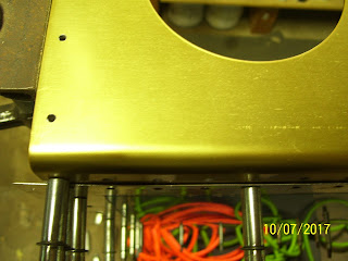
I removed the tank attached to the baffle plate this time, and then I realized something else that I also needed to do. This was the first time since I drilled all the tank baffle plate - to - Z bracket holes that they would all be exposed so that I could check the spacing and edge distance of the new holes in each Z bracket. I think they turned out exactly as expected. Here are some pics:


 With the top sides of these holes exposed I was able to debur them. Then I realized that I needed to debur the matching holes on both sides of the fuel tank baffle plate as well. So I removed the the baffle from the fuel tank assembly that was now sitting on the work bench, and deburred both sides of the drilled baffle plate holes, and I also deburred the aft side of the inboard and outboard tank ribs where they rested on the Z brackets. Then I realized that I would also need to reattach the baffle plate to the tank assembly and eventually remount the tank before I could scarf the wing skin joint. So I reattached the baffle plate, but left it off the wing spar so I could finally finish countersinking the remaining holes in the wing spar flange. It just never ends.
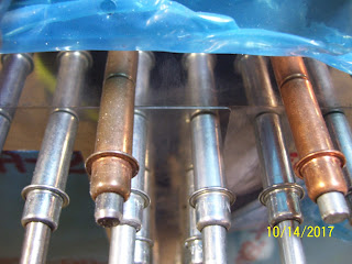
Next is a really blurry pic of the holes that lie under the nut plate holes for the fuel tank attach screws. You can still see the rivet I put in the hole to show that is has the proper amount of over-countersunk depth as specified by Vans in the latest section 5 revision of their manual.
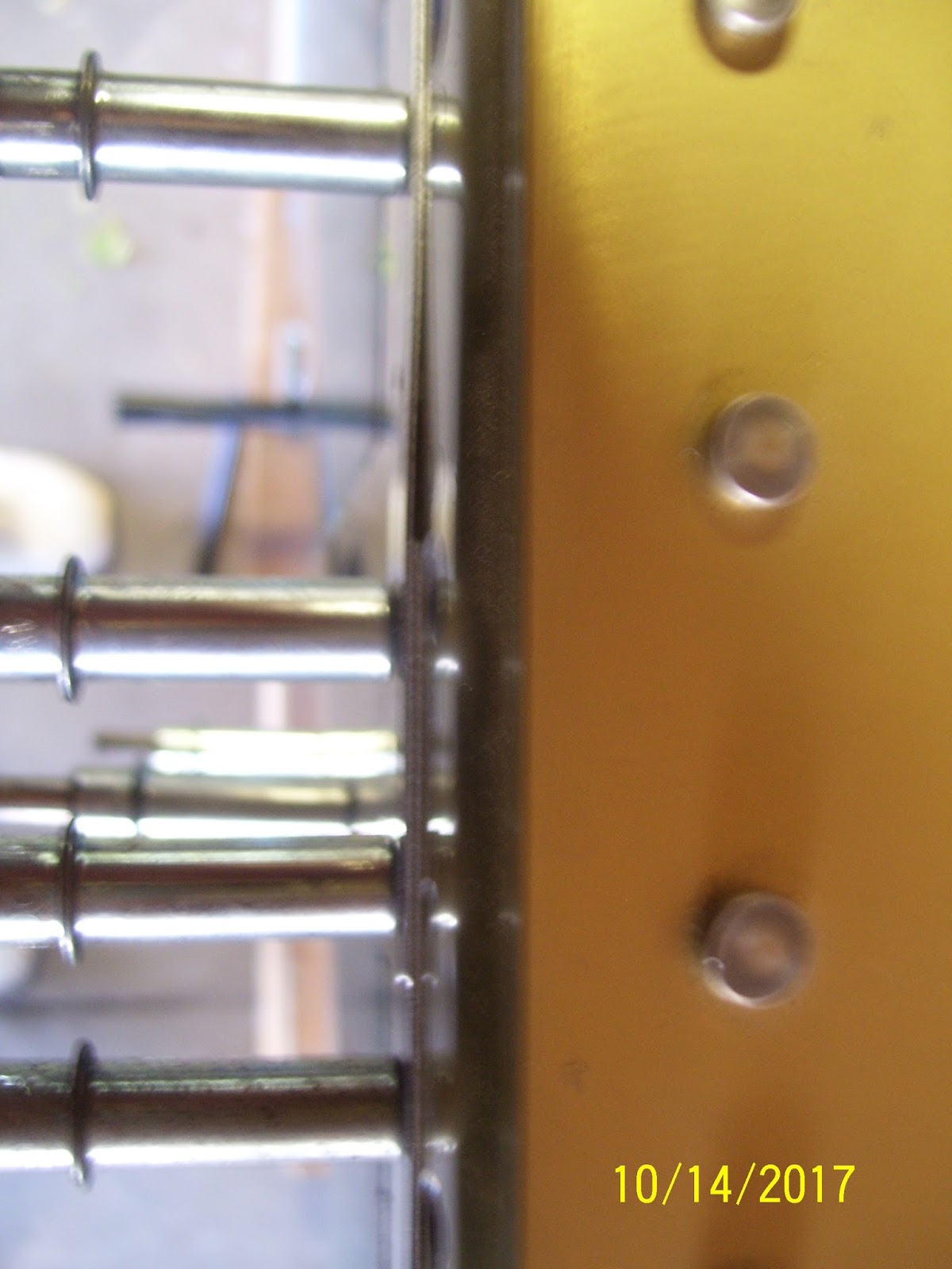
 After all the top holes were re-countersunk, it was time to remount the fuel tank and the outer wing skin to the wing spar in preparation for the scarfing task. Before I remounted the fuel tank, I attached the outer wing skin. these next pics attempt to show the gap between the wing spar flange and the inner and outer top wing skins where they overlap. In this pic I am looking down over the edge of the main wing spar flange where the skins attach to it. The rivets on the right are the doubler rivets on the top and bottom of the main wing spar web. IOW, pretend you are fuel tank skin that is about to butt up to the edges of the skins shown in the middle of the pic.
The skins need to be tapered in this corner so that the gap between the outer skin and the wing spar flange no longer appears, and the two overlapping skins join together flush with each other, and the edges are also flush with the edge of the tank skin.

 After these pics I reattached the fuel tank to the spar and put a #30 cleco through the holes for the screws in the fuel tank skin so that the tank skins on the top and bottom are flush against the top of the wing spar flange, and butted up snugly against the top edges of the wing skins.Then I had to determine how many bays of clecoes I was going to remove from the wing skins so that I could bend each of them out of the way of the wing spar without creasing or kinking them so I could begin the scarfing process.
Others will perform the task with the skins removed from the spar completely, but since the object of this task is to carefully trim down the skin so that it forms a smooth, flush joint with the wing spar flange and the fuel tank skin, the only real way to do this is to start removing small amounts of skin and then check the fit. The only way I could figure to do this efficiently was to keep the skins partially clecoed to the wing frame on the most inner and most outer ribs, leaving the center section completely unattached from the spar, so I could lightly bend each skin back without creasing or kinking it while I grind away the metal a little at a time.
Now for the tools to do the job. Here is a pic of the choices I had. I had the pneumatic die grinder with a 3 inch attachment that holds a screw on attachment for a scotch brite pad or a sanding disk. The scotch brite pads seemed a little uneven to me for this application, so I opted for the 180 grit sanding disk. I also opted for the cordless drill instead of the air grinder so I could have a little better control. I also decided to use the 2 inch attachment instead of the 3 inch attachment, again for better control and to keep the area being removed as small as possible to avoid removing too much material from too large an area on each wing skin.

 The math for this operation is pretty straight forward. The inner skin is .032 inches thick. The outer skin is .025 inches thick. The tank skin is .032 inches thick. The 1.25 inch area where the inner and outer skins overlap creates a combined thickness of .057 inches. Or put another way, the overlapped section is thicker than the .032 inch thick fuel tank skin by the thickness of the outer wing skin. SO you have to figure out how to reduce this overlapped thickness by .025 inches, taking a certain amount away from each skin. Obviously you cannot remove the entire .025 inch thickness of the outer wing skin. However, I am aware of some builders who have actually done this. In fact, this very thing is already done at the factory where the skins overlap at the trailing edge as part of the fitment process for the ailerons and flaps. SO this technique can be used, but I chose to scarf the joint instead per Vans instructions.
So this means that you have to remove a certain amount of skin thickness from the corners of both skins to arrive at the combined removal of .025 inches.The "formula" I came up with was to remove .0200 inches from the thicker inboard wing skin, and .0120 inches from the thinner outer wing skin. Now this sounds fine "on paper," but in practice I found it rather impossible to get an accurate reading from a digital caliper while trying to periodically check thickness in between sanding sessions to see of the correct depth has been reached. The other complication about this is that the skins are supposed to be tapered (scarfed), so if done correctly, the skin changes thickness constantly. So I gave up the caliper approach, and resorted to visual checks of the fit by pushing the skins together and checking for flush against the fuel tank skin.
SO you might ask, why go to all this trouble for a lousy skin joint. Well, the problem is that the overlapping wing skins cause a rise in the skin that sticks up higher than the fuel tank skin, which also serves as the inboard leading edge of the wing. If this skin edge is not made to be flush with the fuel tank skin, it sticks up into the airflow, disrupting it, causing drag and unstable airflow over that portion of the wing. So to prevent all the ill-effects of this, you need to blend the skin joint so that everything is smoothly joined together.
The other thing to note about this process is that you need to leave the flatness of the inner wing skin against the wing spar flange, so that means you only remove material from the top side of that skin, and the bottom side of the outer skin. EDIT - I later determined that I needed to remove it from the other side as well, so I removed material from both sides o the inner wing skin. You also try to keep the scarf joint a couple of inches or so in size, focusing only on removing enough material for the joint in this corner of the skin to be flush with the tank skin. It should not be a large scarf joint.
I'll add more pics of that tomorrow, but for now here is the joint after I worked on both skins a little tonight. I bent out each skin just enough to separate it from the wing spar and allow clearance for the drill and the attachment. I held the skin in my left hand, applying pressure against the sanding attachment applied to the other side of the skin, and started removing small amounts of material at various intervals, checking my progress as I went. When I felt like I might have enough material removed, I checked the fit. When I thought I had it pretty close, I re-clecoed all the skins to the frame. I've still got a little more work to do tomorrow, but I think I am on the right track.

 When I re-clecoed the skins, the fuel tank skin and top edges of the inner and outer wing skins were slightly interfering with each other. I think this may have happened as a result of deburring the tank ribs, baffle plate, and Z brackets, where the tank assembly, and therefore the tanks skins, are sitting just a bit lower than before. The interference is such that a little more edge deburring by lightly sanding each skin will take care of this minor interference. So I am close, but still have a little more material to remove. Hopefully I can finish this process tomorrow.
I then realized that in order to scarf the joint properly, I would really need the skins to be secured as closely as possible to the way that the would be riveted to the wing spar and the ribs, so that I would know exactly how much the skins would need to be tapered (scarfed) to remove the .025 ridge that sits higher than the fuel tank skin when the wing skins overlap each other. They overlap each other by about 1.25 inches or so, with the side by side rivet holes about 7/8 of an inch apart from each other, and each outer-most rivet hole in each skin is set at about 5/16ths of an inch from edge of each skin.
As I thought through this, I realized that although I had countersunk the holes for the inner wing skin rivet that attach it to the wing spar flange, I had NOT yet re-countersunk the rivet holes in the wing spar flange for the outer wing skin. I needed to do this BEFORE scarfing the joint, to ensure that the wing skins were seated properly in the slightly over-countersunk holes, so that the skin edges are sitting flush against the wing spar flange.You cant set a scarf joint very well on two skins that are pillowing where they attach to the spar, so this had to be done beforehand.
SO I grabbed the drill and the MS countersink bit that was still set for the slightly deeper countersunk hole, and started re-doing all the holes for the outer wing skin attach points on the main wing spar flange on the top side. I started from the outboard (wingtip) end and worked my way back toward the fuel tank, which was still mounted on the wing spar. And that's where I ran into my issue. the wing skins overlap each other at a point that extends beyond the outboard end of the fuel tank skin. Therefore there are a small number of additional holes that lie directly under the fuel tank skin that also must be re-countersunk. The problem is that with the tank skin in the way, you can't set the microstop countersink bit flush up against the spar flange to ensure an evenly drilled hole. SO the fuel tank has to come of the wing AGAIN in order to finish countersinking. (UGHHHH)!
I removed the tank attached to the baffle plate this time, and then I realized something else that I also needed to do. This was the first time since I drilled all the tank baffle plate - to - Z bracket holes that they would all be exposed so that I could check the spacing and edge distance of the new holes in each Z bracket. I think they turned out exactly as expected. Here are some pics:


Next is a really blurry pic of the holes that lie under the nut plate holes for the fuel tank attach screws. You can still see the rivet I put in the hole to show that is has the proper amount of over-countersunk depth as specified by Vans in the latest section 5 revision of their manual.

The skins need to be tapered in this corner so that the gap between the outer skin and the wing spar flange no longer appears, and the two overlapping skins join together flush with each other, and the edges are also flush with the edge of the tank skin.

Others will perform the task with the skins removed from the spar completely, but since the object of this task is to carefully trim down the skin so that it forms a smooth, flush joint with the wing spar flange and the fuel tank skin, the only real way to do this is to start removing small amounts of skin and then check the fit. The only way I could figure to do this efficiently was to keep the skins partially clecoed to the wing frame on the most inner and most outer ribs, leaving the center section completely unattached from the spar, so I could lightly bend each skin back without creasing or kinking it while I grind away the metal a little at a time.
Now for the tools to do the job. Here is a pic of the choices I had. I had the pneumatic die grinder with a 3 inch attachment that holds a screw on attachment for a scotch brite pad or a sanding disk. The scotch brite pads seemed a little uneven to me for this application, so I opted for the 180 grit sanding disk. I also opted for the cordless drill instead of the air grinder so I could have a little better control. I also decided to use the 2 inch attachment instead of the 3 inch attachment, again for better control and to keep the area being removed as small as possible to avoid removing too much material from too large an area on each wing skin.


So this means that you have to remove a certain amount of skin thickness from the corners of both skins to arrive at the combined removal of .025 inches.The "formula" I came up with was to remove .0200 inches from the thicker inboard wing skin, and .0120 inches from the thinner outer wing skin. Now this sounds fine "on paper," but in practice I found it rather impossible to get an accurate reading from a digital caliper while trying to periodically check thickness in between sanding sessions to see of the correct depth has been reached. The other complication about this is that the skins are supposed to be tapered (scarfed), so if done correctly, the skin changes thickness constantly. So I gave up the caliper approach, and resorted to visual checks of the fit by pushing the skins together and checking for flush against the fuel tank skin.
SO you might ask, why go to all this trouble for a lousy skin joint. Well, the problem is that the overlapping wing skins cause a rise in the skin that sticks up higher than the fuel tank skin, which also serves as the inboard leading edge of the wing. If this skin edge is not made to be flush with the fuel tank skin, it sticks up into the airflow, disrupting it, causing drag and unstable airflow over that portion of the wing. So to prevent all the ill-effects of this, you need to blend the skin joint so that everything is smoothly joined together.
The other thing to note about this process is that you need to leave the flatness of the inner wing skin against the wing spar flange, so that means you only remove material from the top side of that skin, and the bottom side of the outer skin. EDIT - I later determined that I needed to remove it from the other side as well, so I removed material from both sides o the inner wing skin. You also try to keep the scarf joint a couple of inches or so in size, focusing only on removing enough material for the joint in this corner of the skin to be flush with the tank skin. It should not be a large scarf joint.
I'll add more pics of that tomorrow, but for now here is the joint after I worked on both skins a little tonight. I bent out each skin just enough to separate it from the wing spar and allow clearance for the drill and the attachment. I held the skin in my left hand, applying pressure against the sanding attachment applied to the other side of the skin, and started removing small amounts of material at various intervals, checking my progress as I went. When I felt like I might have enough material removed, I checked the fit. When I thought I had it pretty close, I re-clecoed all the skins to the frame. I've still got a little more work to do tomorrow, but I think I am on the right track.


Thursday, October 12, 2017
Still Working on my to-Do List from the Previous Post
Last night I did manage to dimple all the inboard top side main rib flanges with the pneumatic squeezer. I also removed the inner clecoes from the fuel tank baffle and Z brackets, deburred the holes on the inside of the baffle plate, and re-clecoed the inner and outer ribs of the fuel tank to the tank skin again and the baffle plate. Then I clecoed the inner skin and wing walk doubler back to the frame, and checked the fit of the wing top edge of the skin dimples inserted into the slightly over countersunk holes, and the fit is really nice.
Seeing that, I could not resist but to secure the fuel tank to the screw holes in the wing spar again by using #30 clecoes inserted all the way through the nut plates. Then I pulled some of the blue vinyl away from the tank skin so I could check the fit between the edges of the tank skin and the inner wing skin section, and it looked awesome. I could see no gaps along the edges of the skins at all - everything nice and flush.
I even tried out my new die grinder from HF with a 3 inch 180 grit sanding attachment on some scrap metal, and boy does that thing remove metal fast. I'll have to do this very sparingly when i create the scarf joint, and maybe the cordless drill is the better option for that so I don't remove too much metal too quickly. I was glad I still had 2 mini air hose connectors, one of which I attached to the air inlet of the tool, similar to my other commonly used tools like the squeezer, drill, and rivet gun.
In fact, I think that is the best next step - fabricate the scarf joint between the two skin sections, while the fuel is still secured to the wing spar, and then remove the outer skin to finish re-countersinking all those other remaining holes on both sides of the wing spar.
Tuesday, October 10, 2017
Countersunk the Inboard Top Wing Skin Spar Flange Holes
Tonight I countersunk the holes on the wing spar flange for the inboard top wing skin. Before I did this, I called Van's builder support line to ask two questions:
1. What Pop rivets can I use to rivet the rear rib flanges of the Leading Edge assembly to the Wing Spar Web, instead of bucking the AN470AD-4 rivets called for in the plans.
2. Do I have to deepen my countersink tool a bit more that normal to set the holes properly to receive the dimpled wing skins? If so, how deep do they need to be?
The answer to question 1 was that I can use LP-4 pop rivets instead of the AN470 rivets to make it a bit easier to set the LE rib flanges against the wing spar web. these are structural rivets that hold the ribs of the leading edge firmly against the wing spar, so setting these properly is very important.
The answer to question 2 was to check the updated Section 5 of the Van's instruction Manual which is available on Vans website in the revisions section. Section 5.5 states that for dimpled skins that must fit into countersunk holes, it is best to deepen the countersink by .007 more than when the rivet just sits flush with the skin or spar flange.
To figure out how to do this, I had to do some more research about my micro-stop countersink tool. It has a series of "teeth in a spring loaded cage that allow the depth to be changed in very small increments. In fact, each tooth space is the same as a .001 adjustment in depth, so it is very precise. So in a nutshell, that means that I need to adjust the tool and then countersink a few holes in a test piece until the rivet head sits nice and flush against the skin or flange. Then I need to deepen the countersink by 7 more clicks of the teeth in the proper direction to deepen the hole by that much per Vans recommendation. If you do this and then set the rivet in the hole you end up seeing that the head of the rivet is about 1/64th of an inch deeper than flush. Then you take the rivet out and set a test piece with the dimple inside the countersunk hole, and check to make sure that the test piece sits flush against the skin or flange.
I tried to do all this before I countersunk all the outer wing skin holes, and I though that they were sitting OK with my test piece until I clecoed the skin back onto the spar and found out that those dimples were NOT sitting in those holes very well as my last post or two explains. Here is the triangular teeth of the countersink tool, all meshed together:
 The locking ring on the top unscrews and allows you slide the spring loaded half of the tool back to clear the teeth of the other part of the cage, and then you rotate it the requisite number of teeth to achieve the desired depth. All very nice if you know what depth you are trying to achieve, which, until Vans finally updated their manual to provide this very important information, was a mystery that most builders tried to figure out by trial and error.
Here is the test piece that I used - same as before with some new holes drilled and deburred so I could test several of them to make sure I had the tool set exactly the way that it needs to be.
Note the rivet in each hole, first the one that is flush with top of the metal, and then the one that was set just a bit deeper per Vans suggestion:

 You can just see how the second hole is just a little deeper than the first, and the rivet head is no longer flush with the rest of the metal. remember to double click on the pics in the blog to enlarge them a bit more to show better detail.
And here is a pic of all the tools I had to use just to setup the test piece to make this critical tool adjustment.
 Once I had the tool properly setup, I removed the fule tank assembly temporarily to expose the holes in the spar flange, and then I proceeded to countersink the holes for the inboard wing skin.Then I experienced my next error. Some of these holes coincide with a main rib flange that sits up under the wing spar flange. Each side of each main rib (top and bottom of the rib) has two of these holes. Without thinking, I just assumed that both of these holes would get the same countersunk hole, just as I had done for the outer skins.However, there is no attach point for the fuel tank skins in this area, since they are dimpled and inserted into the countersunk for the #8 screws. These holes are already drilled, and the fuel tank skin is screwed to the flange - NOT riveted, since it is designed to be removable for periodic servicing. Since there is no skin dimple being inserted into these holes, the countersink for the top most rivet hole needs to be flush with the spar flange again. I drilled two of these upper flange holes before I stopped and realized what was going on. So hopefully I will be able to set a rivet with a squeezer in those two holes and make it come out flush with the spar flange. We'll see.
Here is a pic of the countersunk holes in the spar:
 You can see a couple of the ribs where there is an extra hole in between countersunk holes in the top edge of the spar flange where the screws for the fuel tank will go. Those are the rivet holes that need to be flush with the flange and not set too deeply, since no skin dimple will be inserted into these holes.
And finally, two pics that show the test piece with the dimple in it laying on top of the angle with the countersunk holes. the first is with the dimple sitting in the properly countersunk, slightly deeper hole:

And in contrast, here is the same dimpled test piece sitting in the hole where the rivet was sitting flush with the metal (not countersunk enough for the dimpled skin). You can see how it is not sitting flush on the angle. SO this tells me that the info from Vans is correct - dimples that sit in countersunk holes need to be countersunk just a bit deeper for the skins and flanges to fit together properly.
 The reason for all this, of course, is that dimples are round, and countersunk holes have straight edges. SO you have to compensate for the radius of the rounded dimple sitting against the straight edge of the countersunk hole. Kind of like fitting a square peg in a round hole, or vice versa - sort of.
Next steps:
Remove the fuel tank assembly again
Remove the inner clecoes for the rib flange holes that attached the rear baffle plate to the wing spar Z brackets
Replace the tank skin assembly back on the baffle plate
Re-cleco the inner and outer tank ribs to the fuel tank skin again, remove the clecos for the inner and outer rib flanges attaching the ribs to the baffle plate and the Z brackets
Remove the entire tank assembly from the wing
Dimple the inboard main rib rivet holes - top and bottom - with the squeezer
Cleco the top inner wing skin and wing walk doubler back on the wing frame, removing clecoes holding the outer skin in place where the two skins overlap, placing the outer skin over the top of the inner skin edge.
Remove the outer skin
Re-countersink ALL those remaining holes that need to go just a bit deeper that are currently not quite deep enough - YES, I have to go back and drill all those holes I already did once more time.
Reset the countersink for the flush setting and finish countersinking those holes
Debur the top sides of the Z brackets and the rear holes of the Tank baffle plate
Reattach the outer wing skin, and firmly remount the fuel tank by clecoing the inner and outer ribs to the Z brackets again and securing the tank skins with #30 clecoes into the screw holes and nut plates, and check the skin fit along the spar flange.
Then I can FINALLY put the LE back on the wing and secure it so that I can mark and measure for the cut out.
And then we go on from there. Lots of little steps, all done in the proper order. At some point everything comes back off again so I can scuff, clean and prime the inside of the top wing skins. Once that is done and the leading edge assembly is done, they will be ready for permanent riveting to the wing frame.
1. What Pop rivets can I use to rivet the rear rib flanges of the Leading Edge assembly to the Wing Spar Web, instead of bucking the AN470AD-4 rivets called for in the plans.
2. Do I have to deepen my countersink tool a bit more that normal to set the holes properly to receive the dimpled wing skins? If so, how deep do they need to be?
The answer to question 1 was that I can use LP-4 pop rivets instead of the AN470 rivets to make it a bit easier to set the LE rib flanges against the wing spar web. these are structural rivets that hold the ribs of the leading edge firmly against the wing spar, so setting these properly is very important.
The answer to question 2 was to check the updated Section 5 of the Van's instruction Manual which is available on Vans website in the revisions section. Section 5.5 states that for dimpled skins that must fit into countersunk holes, it is best to deepen the countersink by .007 more than when the rivet just sits flush with the skin or spar flange.
To figure out how to do this, I had to do some more research about my micro-stop countersink tool. It has a series of "teeth in a spring loaded cage that allow the depth to be changed in very small increments. In fact, each tooth space is the same as a .001 adjustment in depth, so it is very precise. So in a nutshell, that means that I need to adjust the tool and then countersink a few holes in a test piece until the rivet head sits nice and flush against the skin or flange. Then I need to deepen the countersink by 7 more clicks of the teeth in the proper direction to deepen the hole by that much per Vans recommendation. If you do this and then set the rivet in the hole you end up seeing that the head of the rivet is about 1/64th of an inch deeper than flush. Then you take the rivet out and set a test piece with the dimple inside the countersunk hole, and check to make sure that the test piece sits flush against the skin or flange.
I tried to do all this before I countersunk all the outer wing skin holes, and I though that they were sitting OK with my test piece until I clecoed the skin back onto the spar and found out that those dimples were NOT sitting in those holes very well as my last post or two explains. Here is the triangular teeth of the countersink tool, all meshed together:

Here is the test piece that I used - same as before with some new holes drilled and deburred so I could test several of them to make sure I had the tool set exactly the way that it needs to be.
Note the rivet in each hole, first the one that is flush with top of the metal, and then the one that was set just a bit deeper per Vans suggestion:


And here is a pic of all the tools I had to use just to setup the test piece to make this critical tool adjustment.

Here is a pic of the countersunk holes in the spar:

And finally, two pics that show the test piece with the dimple in it laying on top of the angle with the countersunk holes. the first is with the dimple sitting in the properly countersunk, slightly deeper hole:

And in contrast, here is the same dimpled test piece sitting in the hole where the rivet was sitting flush with the metal (not countersunk enough for the dimpled skin). You can see how it is not sitting flush on the angle. SO this tells me that the info from Vans is correct - dimples that sit in countersunk holes need to be countersunk just a bit deeper for the skins and flanges to fit together properly.

Next steps:
Remove the fuel tank assembly again
Remove the inner clecoes for the rib flange holes that attached the rear baffle plate to the wing spar Z brackets
Replace the tank skin assembly back on the baffle plate
Re-cleco the inner and outer tank ribs to the fuel tank skin again, remove the clecos for the inner and outer rib flanges attaching the ribs to the baffle plate and the Z brackets
Remove the entire tank assembly from the wing
Dimple the inboard main rib rivet holes - top and bottom - with the squeezer
Cleco the top inner wing skin and wing walk doubler back on the wing frame, removing clecoes holding the outer skin in place where the two skins overlap, placing the outer skin over the top of the inner skin edge.
Remove the outer skin
Re-countersink ALL those remaining holes that need to go just a bit deeper that are currently not quite deep enough - YES, I have to go back and drill all those holes I already did once more time.
Reset the countersink for the flush setting and finish countersinking those holes
Debur the top sides of the Z brackets and the rear holes of the Tank baffle plate
Reattach the outer wing skin, and firmly remount the fuel tank by clecoing the inner and outer ribs to the Z brackets again and securing the tank skins with #30 clecoes into the screw holes and nut plates, and check the skin fit along the spar flange.
Then I can FINALLY put the LE back on the wing and secure it so that I can mark and measure for the cut out.
And then we go on from there. Lots of little steps, all done in the proper order. At some point everything comes back off again so I can scuff, clean and prime the inside of the top wing skins. Once that is done and the leading edge assembly is done, they will be ready for permanent riveting to the wing frame.
Monday, October 9, 2017
Pounding More Dimples
Yesterday, after a long day of winterizing the house, sprinkler system, and trailer, I managed to gather up enough time to pound out the remaining dimples in the top inboard wing skin for the left wing - minus the area where the scarf joint goes.
I am also reading ahead in the plans a bit to figure out the details of the fuel tank construction. Last night I ended up on the section that states: "If you are installing the capactive fuel tank sender instead of the float senders, it is best to install those now." So I pulled out a bag of parts that had been sitting on my shelf for a very long time, and pulled out the assembly plans and familiarized myself with the various electrical and metal construction components of this assembly.
SO far it all makes pretty good sense, and the assembly seems pretty straight forward. The part that I don't get has to do with how these things actually work. I understand the concept of capacitance in electronics, storing up current to a certain level, but I don't really understand how it works in the fuel tank as the fuel level increases and decreases, other than the fact that the capacitance changes as the fuel level changes. I also don't quite understand how this system can give you an accurate reading of the actual level of fuel in the tank, if the installed plates that are not located on the ribs at each end of the fuel tank. Instead, they are actually installed on each inboard rib just next to each end rib, and then electric wiring is installed and attached to each plate, and then ultimately to a BNC connector on the inboard rib.
The rest of the system involves a capacitance converter, the other half of the BNC connector, and the wires that run from the converter back to the fuel quantity indicator circuit or gauges. All that gets done during the final stages of the fuselage assembly when you are installing your avionics. Anyway, it was fun studying this assembly, and I am still glad I did NOT go with the float senders, but time will tell, since I read a lot of posts from other builders that say that you still have issues with getting accurate readings from either method.
With the inboard top wing skin dimpled, I need to finish dimpling the inboard main wing ribs, and countersinking the holes in the wing spar flanges, followed by priming those holes. I am fairly convinced that I may also need to go back and deepen the countersinks in all the holes just a bit more so that the dimples will insert properly during riveting, but I need to do some more tests on that before I commit to doing it in the wing spar.
I would have done some of that tonight, but we got snow this morning, and the temps are a bit chilly, my tree in my back yard is dropping very large branches that are breaking off without warning, and we lost power for almost 10 hours (not due to my tree issue thank god, but somebody elses), so I am taking a break tonight.
After all that is done both the inner and outer top skins go back on the spar, with enough clecoes removed around the area where the scarf joint will be applied, so I can bend back the skins just enough to take my cheepo HF die grinder air tool and the sanding and abrasive disk set that I bought, and start removing the material in the corner of each skin per the plans. The only way I can figure to do this properly, without having to put on and take off the wing skins multiple times, is to do it while the fuel tank assembly is secured to the wing spar so that the skins will butt up to each other and you can check the fit, and remove a little more material from one skin or the other as necessary, while everything is still on the spar. I don't want to have to spend hours putting skins on and taking them off until I get the fit just right - I don't want to waste that much time. I may, however, decide to put the attachment in my battery powered drill instead of the air tool, just to prevent myself from taking too much metal off, which would be very bad.
I also called Cleaveland Tools today to ask about their 12 inch long extended back rivet set. I think Mike Rettig may already have one of those so I will hit him up for that this week. I plan on using the beefy flat set that I bought a long time ago and back rivet the skin rivets against that, since many builders report getting better looking rivets on the top skins by using that method, instead of the rivet gun and bucking bar.
So that's a rap for tonight. More exciting stuff tomorrow - same bat time, same bat channel....
KPR, or dimples............
Sunday, October 8, 2017
The Theme for Today was.....More Dimpling of WIng Skins and Ribs
Yesterday I had managed to go as far as I could with the top outer left wing skin panel as far as dimpling is concerned. As previously posted (I think) I missed match drilling two holes. I could have taken an easier path by just independently drilling the hole in the skin and rib/rear spar, but as any of you following my blog have already surmised, doing things the easy way is not my forte. SO I needed to match drill these two holes, which meant putting the outer skin panel back on the frame, match drilling the missing holes, and then removing the skin again to debur the holes properly and dimple them.
SO I did just that today. Since this was the first time I mounted the skin to the ribs and the spar with the dimples and countersunk holes in place, I was able to check the fit as I reclecoed the holes. At first there was some misalignment of all holes on the inboard edge for some reason, but using a graduated approach to clecoing the holes, and they managed to align themselves pretty well.
Once this was done, I we to check the fit of the skins to the ribs and the spar with the dimples. I was pretty happy with the dimple-to-dimple fit of the skins to the rib flanges, but the ft of the dimples to the countersunk holes in the spar is another story. I don't seem to be able to use a "test" dimple on some short piece of aluminum very well. I just can't tell if it actually fits. The problem is that trying to verify the fit of something on the wing spar flange is difficult for me because the flange is bent, and there is only a small portion of the test piece that rests on the small flat part of the spar flange I cannot tell if the test dimple and the metal surrounding it are actually fitting correctly, because if I apply a little pressure to it it seems to end up flush with the spar.
Other folks with videos of this always show some test dimple and a another "test" piece of aluminum, but they never show the test piece up against the actual part, such as a wing spar flange. I find this to be troublesome. Are you supposed to have a little spring back with the dimple in the countersunk hole, or none. I do know that if the countersunk hole is too deep, you risk denting the skin as you rivet it, which causes other major problems. SO you definitely do not want to end up doing that.
Anyway, the edge of the skin where the dimple fits into the countersunk holes of my wing spar appear to be "pillowing" just a bit when clecoed. this is a sign that the countersunk hole may not be deep enough for the dimples. This will become even more pronounced once you try to rivet these holes. MY problem is that the pillowing seems to be evident in between clecoes as shown the next pics:

 However, if I put clecoes in every hole, they seem to tighten up. I watched some videos of other builders today who demonstrated that if you are placing a dimple in a countersunk hole you have to enlarge the countersunk hole quite a bit to allow the dimple to rest in the hole properly. In fact, from the examples I saw, it looked like it took 1/32 of an inch more depth to make it fit properly for a dimple, as measured by the exposed metal at the top of the hole if you put an AN426AN- 3 rivet in the hole.
Then you can take a caliper and measure the width of the dimple and the hole and compare them to see if the edges of the dimple should fit inside the the countersunk hole. The last time I had to deal with this, and frankly I am about to find out if I did it right back then, was when I was countersinking the holes for the #8 nutplates and screws in the wing spar for the fuel tank. That was a long time ago, and it was not for any 3/32 holes that would be receiving a dimpled skin. SO this feels like some new territory.
Sounds like I have some more tests to run to see if I need to enlarge my countersunk holes a bit more or not. Anyway, with that first fit completed, it was time to remove the inboard wing skin and debur and dimple it AND the wing walk doubler, which I have not laid my eyes on for a very long time. I removed that skin and proceeded with checking the holes again and deburring them again as necessary, and filed those bumps on the edges, then deburred the edges, rounded off the corners, formed the small bend in the skin edges, and dimpled as many holes as I could reach with the pneumatic squeezer.
I also did some math to try to figure out how much material in each wing skin I need to remove to scarf the joint that sits next to the fuel tank skin where the inner and outer wing skin panels overlap. I need to get some attachments for some sanding disks for my die grinder tomorrow at Harbor Freight so I can complete that little fabrications exercise.
Here is the inner skin on the dimpling table. Since this skin section is smaller than the outer one, it was much easier to maneuver and flip this skin panel on the work bench. I also took a pic of the partially dimpled wing walk doubler.


 Tomorrow I finish dimpling the holes I could not reach with the squeezer, scarfing the corner of the inner and outer wing skins, and then it will be time for final edge prep, then scuffing, cleaning and priming all the interior portions of the skins and the wing walk doubler.
Mainly I wanted to get to a point where I can remount both dimpled wing skins to the frame and then mount the LE again to layout the pattern for the cuts in the outer skin. That was the original part of the plan several days ago.
Winter arrives tomorrow night and into Monday, but it looks like things recover for the rest of the week.I'm getting closer to some major assembly steps and actually slamming some rivets.
SO I did just that today. Since this was the first time I mounted the skin to the ribs and the spar with the dimples and countersunk holes in place, I was able to check the fit as I reclecoed the holes. At first there was some misalignment of all holes on the inboard edge for some reason, but using a graduated approach to clecoing the holes, and they managed to align themselves pretty well.
Once this was done, I we to check the fit of the skins to the ribs and the spar with the dimples. I was pretty happy with the dimple-to-dimple fit of the skins to the rib flanges, but the ft of the dimples to the countersunk holes in the spar is another story. I don't seem to be able to use a "test" dimple on some short piece of aluminum very well. I just can't tell if it actually fits. The problem is that trying to verify the fit of something on the wing spar flange is difficult for me because the flange is bent, and there is only a small portion of the test piece that rests on the small flat part of the spar flange I cannot tell if the test dimple and the metal surrounding it are actually fitting correctly, because if I apply a little pressure to it it seems to end up flush with the spar.
Other folks with videos of this always show some test dimple and a another "test" piece of aluminum, but they never show the test piece up against the actual part, such as a wing spar flange. I find this to be troublesome. Are you supposed to have a little spring back with the dimple in the countersunk hole, or none. I do know that if the countersunk hole is too deep, you risk denting the skin as you rivet it, which causes other major problems. SO you definitely do not want to end up doing that.
Anyway, the edge of the skin where the dimple fits into the countersunk holes of my wing spar appear to be "pillowing" just a bit when clecoed. this is a sign that the countersunk hole may not be deep enough for the dimples. This will become even more pronounced once you try to rivet these holes. MY problem is that the pillowing seems to be evident in between clecoes as shown the next pics:


Then you can take a caliper and measure the width of the dimple and the hole and compare them to see if the edges of the dimple should fit inside the the countersunk hole. The last time I had to deal with this, and frankly I am about to find out if I did it right back then, was when I was countersinking the holes for the #8 nutplates and screws in the wing spar for the fuel tank. That was a long time ago, and it was not for any 3/32 holes that would be receiving a dimpled skin. SO this feels like some new territory.
Sounds like I have some more tests to run to see if I need to enlarge my countersunk holes a bit more or not. Anyway, with that first fit completed, it was time to remove the inboard wing skin and debur and dimple it AND the wing walk doubler, which I have not laid my eyes on for a very long time. I removed that skin and proceeded with checking the holes again and deburring them again as necessary, and filed those bumps on the edges, then deburred the edges, rounded off the corners, formed the small bend in the skin edges, and dimpled as many holes as I could reach with the pneumatic squeezer.
I also did some math to try to figure out how much material in each wing skin I need to remove to scarf the joint that sits next to the fuel tank skin where the inner and outer wing skin panels overlap. I need to get some attachments for some sanding disks for my die grinder tomorrow at Harbor Freight so I can complete that little fabrications exercise.
Here is the inner skin on the dimpling table. Since this skin section is smaller than the outer one, it was much easier to maneuver and flip this skin panel on the work bench. I also took a pic of the partially dimpled wing walk doubler.


Mainly I wanted to get to a point where I can remount both dimpled wing skins to the frame and then mount the LE again to layout the pattern for the cuts in the outer skin. That was the original part of the plan several days ago.
Winter arrives tomorrow night and into Monday, but it looks like things recover for the rest of the week.I'm getting closer to some major assembly steps and actually slamming some rivets.
Thursday, October 5, 2017
Dimpled the Top Outer Main WIng Skin Tonight
With just about all of wing spar flange holes for the fuel tank, LE, and main wing skins countersunk, the next logical step was to dimple the main wing skins, starting with the top ones, since they will be riveted to the wing first, when the time comes.
I was a little apprehensive about this at first, for the following reasons:
1. These are the longest and probably the widest skins of the entire airplane, so keeping them clear of obstructions or things that could put a ding in them is a challenge
2. The C-Frame is only so deep, and it is not deep enough to dimple all the rib holes in the skin without turning the skin around, but it does get most of them in one pass.
3. I needed to make sure that the skin would not get caught on my bench vise. I used the blankets to prevent this from happening.
4. Ever since I decided where to place the wing stands, I was concerned about the amount of space between the wings and the work bench, specifically for this situation where I would have to dimple the wing skins. It turns out that there is "just enough" space here to be able to work with the skin by turning it slightly in one direction or the other as you dimple the holes furthest to the rear. This brings the front end of the skin outward toward the wing frame. SO you have get creative, but not near as creative as I had to get with the pre-bent LE skin.
5. You have to have almost double the length of the skin available as room on a bench or a table to allow the sliding of the skin from one end to the other as you dimple all of the holes.
As it turned out, everything worked out fine. Unfortunately, I missed match drilling a couple of holes out of hundred or so that are drilled, so that wasn't too bad. I'll get those taken care of just as I did for the ones I missed on the LE skin after I cleco it back on the wing frame. ow you determine that, as I said before, is you pay very careful attention to how the male dimple die fits into the hole. If it does not freely adn easily insert itself into the hole, then most likely it has not been match drilled. Whatever you do, do NOT try to dimple a hole like that, or you will end up with a ding that will need to flattened, or worse yet, a badly formed hole in the skin that needs to be addressed.
I also used the pneumatic squeezer to dimple as many holes as possible around the perimeter of the wing skin, so that I did not have bang as many of them with the C-Frame. You also need to be careful not to try ot dimple two sets of holes in this skin yet. the first set are the farthest holes in the outer portion of the skin. These are the attach holes for the wing tip, and you do not address these until the wing is essentially finished. The other set of holes that you do not touch yet are the holes for the aileron gap seal and the flap support bracket. These are both on the trailing edge of the wing and are mounted after the row of holes that attach the skin to the rear wing spar flange.
I turned the skin over before I started dimpling to debur the edges on the other side of the skin, and to apply the small bend in the top of the skin edge where it attaches to the wing spar flange, to prevent it from curling up when riveted. I used the edge forming tool for that, and it went rather well once I got the depth adjusted correctly. I still need to round the corners just a bit and get the back side of this skin by filing those bumps and deburring that edge.
I guess that I should also mention that I temporarily took the fuel tank assembly and put it back on the wing spar. I needed the space on the second work bench for clearance to dimple the skin, and with the LE in the cradle, The only spot for the fuel tank is back on the spar.
Here is a pic of the skin on the dimpling table
 Next is the blanket over the bench vise
 Next is the skin with some of the holes dimpled
 Next is pic of the lack of space you have as the skin comes outward. At its worst points, I had to turn the corners of the skin so I could get close enough to the ram while the male dimple die was held in the hole on the table. IN another case when the ends of the skin start to interfere with objects near the work bench, such as refrigerator, you can curve the skin up against those surfaces while the rest of the skin stays flat on the table, this works just fine.
 The last pic shows several holes on the inboard upper corner of the wing skin that I did not dimple yet. The reason for this is that you are supposed to leave an area of about 3-4 inches in this corner to form the scarf joint where the inner an outer wing skins overlap. All that simply means that you need to taper the thickness of the corners of both the inner and outer wing skins on both the top and bottom of each wing so that they flow into and match the thickness of the .032 fuel tank skin. This requires grinding, filing, or sanding the skins in this area to reduce the thickness of each one. So there is no point in dimpling these holes yet until that joint is scarfed.
 This skin now needs to be clecoed back on the wing frame after removing the top inner wing skin to counterskink the remaining wing spar flange holes adn dimple the holes in that skin, as well as the wing walk doubler, which frankly I have not seen for a very, very long time since both of them were clecoed to each wing frame. I do know that I never primed that doubler, and the inside of each wing skin also need to get scuffed, cleaned and primed, so there will be some more painting in the near future,
After I dimpled all the holes in the skin, I turned over the skin to check the top side to see how well the dimples were formed. I have to say I was very happy with these, because they are very crisp and clean and appear to be very well formed. I recently saw a fellow builders RV-7A and was looking at his wing skins, and his rivets and dimples looked very nice as well. This means that the height of my dimpling table is set just right, where the male dimple die is in the set holder and it sits just proud of the rest of the carpeted table, so that the dimple dies are contacting the metal skin when the dies are hammered together.
After I get the top skins dimpled, it will be time to address the remaining work on the LE mod. I also came up with a plan for making a mock up of it using some old aluminum angle and some 1/16th inch aluminum from HD to fab the wing spar web, and I can attach some additional angle to use as a clamping platform. Then I can rivet the two ribs to the mocked up wing spar, fab another subskin and outer skin, and make the cutout, just like I am doing on the real part.
I think I will still need to do this when I finally start fabbing the gun nacelles for the lights that I plan to use. I do need to make sure that the gun ports are strongly attached, and also blend into the front of the LE very well. That will involve some foam and fiberglass experimentation with making a mold for the light mounts. I can do all that on the mock up until I know that I have all the kinks worked out of that process.
KPR
I was a little apprehensive about this at first, for the following reasons:
1. These are the longest and probably the widest skins of the entire airplane, so keeping them clear of obstructions or things that could put a ding in them is a challenge
2. The C-Frame is only so deep, and it is not deep enough to dimple all the rib holes in the skin without turning the skin around, but it does get most of them in one pass.
3. I needed to make sure that the skin would not get caught on my bench vise. I used the blankets to prevent this from happening.
4. Ever since I decided where to place the wing stands, I was concerned about the amount of space between the wings and the work bench, specifically for this situation where I would have to dimple the wing skins. It turns out that there is "just enough" space here to be able to work with the skin by turning it slightly in one direction or the other as you dimple the holes furthest to the rear. This brings the front end of the skin outward toward the wing frame. SO you have get creative, but not near as creative as I had to get with the pre-bent LE skin.
5. You have to have almost double the length of the skin available as room on a bench or a table to allow the sliding of the skin from one end to the other as you dimple all of the holes.
As it turned out, everything worked out fine. Unfortunately, I missed match drilling a couple of holes out of hundred or so that are drilled, so that wasn't too bad. I'll get those taken care of just as I did for the ones I missed on the LE skin after I cleco it back on the wing frame. ow you determine that, as I said before, is you pay very careful attention to how the male dimple die fits into the hole. If it does not freely adn easily insert itself into the hole, then most likely it has not been match drilled. Whatever you do, do NOT try to dimple a hole like that, or you will end up with a ding that will need to flattened, or worse yet, a badly formed hole in the skin that needs to be addressed.
I also used the pneumatic squeezer to dimple as many holes as possible around the perimeter of the wing skin, so that I did not have bang as many of them with the C-Frame. You also need to be careful not to try ot dimple two sets of holes in this skin yet. the first set are the farthest holes in the outer portion of the skin. These are the attach holes for the wing tip, and you do not address these until the wing is essentially finished. The other set of holes that you do not touch yet are the holes for the aileron gap seal and the flap support bracket. These are both on the trailing edge of the wing and are mounted after the row of holes that attach the skin to the rear wing spar flange.
I turned the skin over before I started dimpling to debur the edges on the other side of the skin, and to apply the small bend in the top of the skin edge where it attaches to the wing spar flange, to prevent it from curling up when riveted. I used the edge forming tool for that, and it went rather well once I got the depth adjusted correctly. I still need to round the corners just a bit and get the back side of this skin by filing those bumps and deburring that edge.
I guess that I should also mention that I temporarily took the fuel tank assembly and put it back on the wing spar. I needed the space on the second work bench for clearance to dimple the skin, and with the LE in the cradle, The only spot for the fuel tank is back on the spar.
Here is a pic of the skin on the dimpling table


After I dimpled all the holes in the skin, I turned over the skin to check the top side to see how well the dimples were formed. I have to say I was very happy with these, because they are very crisp and clean and appear to be very well formed. I recently saw a fellow builders RV-7A and was looking at his wing skins, and his rivets and dimples looked very nice as well. This means that the height of my dimpling table is set just right, where the male dimple die is in the set holder and it sits just proud of the rest of the carpeted table, so that the dimple dies are contacting the metal skin when the dies are hammered together.
After I get the top skins dimpled, it will be time to address the remaining work on the LE mod. I also came up with a plan for making a mock up of it using some old aluminum angle and some 1/16th inch aluminum from HD to fab the wing spar web, and I can attach some additional angle to use as a clamping platform. Then I can rivet the two ribs to the mocked up wing spar, fab another subskin and outer skin, and make the cutout, just like I am doing on the real part.
I think I will still need to do this when I finally start fabbing the gun nacelles for the lights that I plan to use. I do need to make sure that the gun ports are strongly attached, and also blend into the front of the LE very well. That will involve some foam and fiberglass experimentation with making a mold for the light mounts. I can do all that on the mock up until I know that I have all the kinks worked out of that process.
KPR
Wednesday, October 4, 2017
Countersunk a Million Rivet Holes
Well, it felt like a million holes at least. Tonight I worked on the Main wing spar to get the remaining main wing spar flange holes countersunk for the dimples in the main wing skins, which I am going to start on tomorrow. Yesterday I also edge-deburred 3 of the 4 sides of the top outer wing skin. I also filed away those pesky points on the edge of the skin where it separates from the metal sheet that it is cut from on the CNC machine at the factory. These are potential sources for stress risers in the skin that could lead to cracks and fatigue. I think some builders leave these as is because they probably don't even realize they are there. I can feel them with my finger. Chalk that up to years of building plastic models where you had to remove each part from the plastic tree on which each part is molded. You had to clean up those edges to.
SO now most of the rivet holes in main wing spar flanges have been countersunk. I also called Vans today to ask about the corner of the skins that overlap when you form a lap joint with the inner and outer wing skins.This corner gets filed down so that the edges of the overlapping wing skins butt up flush with the fuel tank skin. I needed to find out if I am still dimpling those skins where they get thinned down quite a bit. The answer was yes.
Now for more about Dan's method to "remove" the LE assembly, which caused me such grief the other day. In fairness to Dan, when he came up with his idea to properly position the tank baffle to ensure that the skins all butt up to each other properly, which Van's instructions would NOT guarantee, he was experimenting with this for the first time. Dan did his Right wing first, followed by his left wing.
What I found out after I read ahead in his build log and reviewed how he did this for the left wing, was that he DID detach the clecoes holding the 408 LE rib and joiner plate to remove the LE from the wing spar while still leaving the fuel tank firmly attached to the wing spar. So the problem was that the first time he did this on his right wing, he did not post anything about that crucial step in this process. However, for his left wing, he not only wrote about this critical step, but he also took a picture of it.
SO as with all experiments, you learn a bit more each time you repeat the process. Had I been smart enough to read ahead to his left wing assembly, I would have seen this and not tried to destroy my LE like an idiot.
I also wanted to mention that Vans was absolutely no help in this department, but not for the reasons I mentioned in an earlier post. After I re-read their instructions today, they basically have you attach the LE to the wing spar, and then they tell you to laeve the LE there and "get to work on the fuel tank." then after you do all fuel tank work, you don't see another word about the Le until AFTER ALL of the fuel tanks assembly is complete. I mean sealed, riveted - COMPLETE. Then the next thing they tell you is to rivet the LE in the cradle OFF the WING - but they NEVER tell you when to 'remove the LE from the wing spar after you left it there. typical Vans instructions severely lacking in critical points of the build. Ridiculous.SO if you followed their method, you would still end up scratching your head about how and when to remove that LE assembly.
Lastly for tonight, before I can start riveting the LE together, I have to perform the final steps to make the cutout of the LE skin. I called Jim Elliot to discuss this with him again. The main questions were if I should leave enough outer skin in between the ribs of the bay in question that I will be cutting so that another line of rivets could secure the outer skin to the subskin to secure that area from bending or twisting and possibly cracking. The answer was yes, and use the same rivet pitch as was done on the rivets that attach the skin to the rib flanges and the subskin. SO I will be leaving about 1.5 inches or so of extra outer skin next to each rib to provide enough room for a line of rivets relatively close to the existing rivets that attach the skin to the ribs and the subskin. And then there will be enough rove to install a line of K1100-8 nut plates along the sides as well. this is consistent with information about this sort of things in AC43-14 for lap joint types of "repairs" which is similar to what I would be doing.
I also took a closer look at the lap joint or splice joint that is used to join the outer and inner wing skins, and noted the spacing and rivet pattern that they used for that area, again which is very similar to what I will be doing with the LE. SO this gave me something to measure and to look at so I could see how this setup might look when I do it on both sides of the skin next to each rib.
The next decision was what type of radius to use for the rear part of the cutout. After using the 1/2 inch radius or the new access panel, I think I am going to stick with that for the transition of the cutout from along the sides to the rear portion on the top and bottom of the outer skin. this makes a nice large transition that won't load up the corners as much as a smaller 1/4 inch or 1/8th inch radius would. It also makes for a nice wide round corner to fit the removable LE skin up against when you mount it the LE.
SO I think I am very close to making some final measurements for cut lines and rivet lines, spacing adn patterns,as well as the number of nut plates and screws to use. I have also decided that the cutout will go back as far as the 4th or 5th rivet along each rib. Since the RV wing is very thick wing plan form, this means that the size of the removable LE that I will be making is still going to seem pretty large as it wraps around the subskin from top to bottom. And there is something to consider about how cutting away a smaller size is safer because I can always make it larger if necessary. But it is impossible to go the other way. If I remove too much, I can;t get it back. So this is that last nerve racking decision to make to determine the ultimate size of the removeable LE.
This is also where I had said that I would make a mock up of the assembly to get a feel for how this go, but the fact of the matter is that I think I have planned and researched this whole thing out to the point where I feel pretty comfortable with all the remaining steps that need to be completed to make this monster idea into a reality.
Anywhoo, I'm rambling about all this again just to make sure I capture it in writing. When I am ready, and the layout is drawn out and measured, it will be time to remove the 2 ribs and the subskin for one last final time, and make the cuts in the outer skin and finish trimming up the subskin to its final form.
KPR
Tuesday, October 3, 2017
Almost ruined the LE yesterday....
This is where I get to rant once gain about those that do not provide enough information to ensure that things get done properly. As a result of this lack of information, and my own shear stupidity, I almost ended up destroying my inboard leading edge rib while trying to get the damn thing off the wing spar per the instructions you get from all these web sites using the "Checkoway" method.Well, now that I have experienced the "Checkoway" method first hand, which actually mirrors a similar useless instruction from Vans, I am here to tell you that for this little part of the procedure - the method sucks!
To understand this, I'll review what is going on here.
1. You are trying to mate the LE skin to the fuel tank skin and the top wing skins to ensure that all the skins have a nice fit up against each other with no gaps, and that the joiner plate is properly positioned for match drilling the screw holes in the fuel tank skin to the joiner plate extension from the LE.
2. This means that the LE is clecoed to the wing spar nice and tight, and the fuel tank is clecoed to the wing spar using the #30 clecoes in the fuel tank skin holes through the nut plates for the screw holes - also nice and tight.
3. The other reason why you want this joint to be tight and straight is that there is a joiner plate that connects the fuel tank skin to the LE skin, and there is not a lot of room on this joiner plate for the nutplates and #8 screw holes. So the holes for the screws and nutplates for that thing also have to be drilled in just the right place.
4. Once you match drill the #30 holes in the fuel tank skin and the joiner plate of the LE, the Checkoway instruction tells you to "REMOVE the Leading Edge from the wing spar."
5. The other important thing to note is that the fuel tank is supposed to remain fully attached to the wing spar while you "remove" the LE assembly so that you can properly position the rear baffle plate and drill all the rib to baffle to Z bracket holes, starting with the inboard rib, followed by the outboard rib. SO you can't remove any clecoes or anything else from the now-secured fuel tank to allow you to remove the LE, or you defeat the purpose of mounting everything together in the first place.
6. The joiner plate extension sits UNDERNEATH the fuel tank skin. So with everything clecoed together you cannot just lift the LE assembly straight up off the wing spar with the fuel tank still secured to the wing spar, as the joiner plate will interfere with that.
SO I did all the above, and it was working out rather well. Then I removed all the clecoes holding the LE to the wing spar, and tried to "remove it from the wing spar" per the instructions. The problem was that something was not "letting go" as I tried to remove it, and at first it felt like a cleco was still holding it to the wing spar. Three full repeated checks later, I confirmed there was NO cleco holding the LE to the wing spar. SO why was the LE hanging up, and on what?
Like an absolute idiot, I decided that maybe I just need to pull harder because the fit of the LE joiner plate to the fuel tank was very tight. The reality, and the truth to this situation, is that in order to get the LE off the wing spar you have to slide it out toward the wing-tip side of the spar, to try to clear the joiner plate from under the fuel tank skin. Then you should be able to lift it straight up and out. Well, all these idiots seem to forget to tell you that their are two problems with this:
1. The edges of the rear flanges of the LE ribs sitting flush against the wing spar web when the LE assembly is on the wing spar sit VERY CLOSE to the shop heads of the forward flanges of the main wing ribs that are already riveted to the wing spar web.
2. In order to slide the LE toward the wing tip part of the spar, you must lift the LE skins up and over your support bracket that holds the wing spar onto the wing stand. This is because the LE skins extend downward past the mounting stand bracket so they can be attached to the wing spar flange along each flange of the wing spar. This puts the LE at an angle, which unfortunately results in the inboard rib flanges of the LE digging into the wing spar and angled toward the shop heads of the rivets even further.
At one point I pulled so hard that "something" finally gave way. Upon removing the LE assembly I found out what that "something" was. One corner of the rear flange of my most-inboard 408 rib had been folded back to about 120 degrees, as it got caught on the edge of one of the shop heads of the main wing rib rivets as I tried to pull it away from the secured fuel tank assembly harder and harder. This also distorted several bends in that entire rib flange, and even bent the rib web slightly out of alignment.
I think I was able to repair the rib by bending everything back in place as much as possible, but Lord only knows what may have happened to my already enlarged rivet holes for that rib, subskin, and outer skin with all that tugging that I did.. I used pliers and my metal straightening/bending tool to try to flatten out the edge of the rear rib flange. It did not crack as far as I an tell, but it was obviously severely stressed.
I just can't believe how stupid I was. Note to self - if the part won't move, it is hung up on something! Stop what you are doing and figure out what it is hung up on, and then figure out how to solve the problem intelligently.
SO here is that "something else" that NOBODY seems to mention in their builders logs or posts to their blogs when they get to this step. I submit this in the event that my stupidity might prevent another builder from making the same mistake that I did.
I reasoned that "normal builders" that only use the small 1.5 inch wide joiner strip per the plans, end up with some "give" in the 1.5 inch wide strip when they lift up on the LE and start sliding it off of the wing spar. This also allows the rear flanges of that first LE rib to lift up high enough to clear the shop heads from the main wing spar rivets as it starts to move away from the fuel tank, and off it comes. OR.......
What probably REALLY happens is that they remove the clecoes that hold the first inboard 408 rib to the LE skin and the joiner strip, and this frees up the entire LE assembly so that it can be lifted STRAIGHT UP instead of OUTWARD. Then the joiner strip can be removed from the fuel tank, and all is well.
But try to find that little blurb in someone's build log - it never exists, and why that is, I will never know.
SO in my case, I would have needed to remove clecoes from both inboard ribs to release the LE skin from the modified joiner plate/subskin that spans the distance of both of those ribs (12 inches wide). Had I done that, all of this would have been avoided, and I would not be stressing further over the integrity of this stupid part of mine.
I'm pretty frustrated over my own stupidity, and I'm absolutely mystified about how others that work on this phase of the build do not comment on any difficulty with removing the LE assembly after the fuel tank is secured to the wing spar. I guess they must be smarter than me.
I think I escaped this stupid mistake without too much damage, but I won't know for certain until the time comes to rivet the LE to the wing spar for the final time.
On a more positive note, I did some more work on the fuel tank baffle and Z bracket rivet holes tonight, but I'll update that work tomorrow with some pics.
Sunday, October 1, 2017
Continuing with Dimpling and CounterSinking holes for the LE
Starting with some pics from the dimpling of the LE outer skin mentioned in my previous post:

 This was a bit of a chore that required me to clear away a large area of the work bench to be able to maneuver it so that each hole could be dimpled. This was complicated for me because my dimpling table is on the bench, the back side of which is right up against the wall. So this restricts my ability to position the parts and also to position myself so that I can hold and hit the ram with both hands to properly form each dimple. Since space is restricted I found that I have to get very creative about how I position myself to be able to set these dimples. Translated another way, it means that I have to bend my body in some very unnatural and uncomfortable ways to be able to do this.
SO I can tell you right now that I am not looking forward to dimpling the larger outer wing skins, and I may go ahead and try to set up a level method on the garage floor, away from the work benches, just so it will be easier to move both myself and the sink around on the dimpling table without risking throwing my back out of whack. Not fun.
The next 2 pics show my re-assembly of the LE after I got most of the skin dimpled, except for the several holes that I missed match drilling as I mentioned in my previous post. I started reassembling by clecoing the subskin to the outer skin first, just to try to align the dimples. then I decided to reattach the center ribs first, followed by the outer ribs and then finally the inner ribs. I had numbered each rib with a piece of tape to ensure that each rib was reassembled in its proper place. (Read on for a humerous blunder that I made regarding the rib position).
Some complications arose:
1. I discovered that I had not dimpled two of the forward most holes in the subskin - I just missed them after I finally decided to dimple all the holes. So I had to detach the subskin, dimple the holes, and reattach it again - more wasted time.
2. After the LE was completely reassembled, it was time to put it back on the wing spar so I could match drill the remaining skin holes to the wing spar that I missed, and to match drill the W-423 joiner plate holes for the nut plates between the fuel tank and the LE. The only problem was that when I tried to reattach the LE rear rib flanges to the main wing spar web, I would not get the clecoes inserted into the end-most holes in the #3 rib position.
I removed the LE several times trying to figure out what was wrong. the first time I thought it was excess primer in the holes, so I ran a #30 drill bit through each rib hole.Then I put it back on the wing spar, but still had the same problem. SO I took it off again. This time I noticed that one of the rear rib flanges had 2 extra holes in it, and I remembered that one of these ribs had rear flanges that were pre-drilled from the factory, but they must have been a different hole pattern for an RV-6 or RV-7. SO for the RV-8, they tell you to match drill 2 new holes in this rib and to disregard the other holes.
It was then that I realized that I must not have the right rib in the right location. And sure enough, when I checked the rivet hole pattern for each rib flange on the main wing spar, that was exactly the problem. The funny thing is that I think I messed this up clear back to when I primed each of the LE ribs. I remember picking them up from my priming table when I was all done, and I was all but certain that I had picked them up in the proper order. it just so happens that this number 3 rib has a slightly different rivet pattern that the rest of the ribs. SO once I switched the #3 and #4 ribs to the proper locations, everything magically fit back together again properly, but NOT before I had removed and replaced the LE assembly on and off the wing spar about 4 times. So that was last night's big blunder:

 After resolving that problem, all the ribs seemed to fit nicely in the dimples with the skin. The next step was to set my microstop countersink tool to the proper depth by testing it on some scrap pieces. it is amazing that you can set this tool to provide a countersink that is accurate to 1/64th of an inch. I put a piece of angle between 2 drill boards and marked several holes that are far enough apart for the frame of the countersink tool. then drill drilled the holes and used a rivet to check the depth.
This procedure is also perplexing to me, because I am able to set the tool so that the rivet heads do sit perfectly flush in the holes. But the problem is that every time I actually set rivets in these hole to attach parts together, the rivets seem to end up slightly proud of the top part being riveted. This happened quite a bit when I did the holes for the fuel tank nut plates long ago.
So then yo are left with a decision to make - if you should counterskink just a little bit deeper or not so that the rivet truly does end up flush. The question then becomes, how much deeper do you countersink? SO I did some tests with a few different settings and decided which one I wanted to use, and proceeded with the holes in the wing spar flanges.


 The other piece of metal in the top pic was a test piece that I made with one dimple in it to check the depth against the spar flange after the countersink holes was drilled. The test is to see if the dimple fits correctly in the countersunk hole so that the skin then sits flush with the spar. My past experience with this is that the parts tend to get slammed together pretty good with you actually rivet them together, so if the trial fit with the test piece looks good then it should definitely be that way when everything actually gets riveted together.
With the depth set, I went ahead and countersunk all the spar flange holes for the LE skin. About 128 per side for the LE. I think they came out pretty good, and the real test was clecoing the LE in place again. The skin seems to butt flush against the spar flange along the entire span, so I am happy with the results.
I then match drilled the missing holes, which I will have to debur, dimple, and countersink when the LE comes off for what should be the final time.
The last thing I did was to secure the fuel tank assembly next to the LE, so that I could FINALLY match drill the joiner plate screw holes that secure the tank to the LE skin. I was a little surprised that after dimpling and securing the LE and then butting it up against the tank that the bottom side skin has a small gap, but the edges from the middle to the tip of each skin seem to match up just fine. The top side of the skin does not seem to have this gap. I was a little disappointed, because prior to dimpling the LE this joint was completely perfect, with no gap. I guess I will have to wait until I dimple the tank skin screw holes and get it ready for riveting until I will no for certain if there is still a gap there or not.
Here are the shots of the bottom and top side skins of the tank and the LE with everything tightly secured with clecoes. The holes for the screws for the fuel tank skins that attach it to the wing spar flanges are secured with #30 clecoes that go all the way through the #8 nut plates that were attached to the wing spar flanges a long time ago.


The last pic is of the end of the wing along the wing spar flange line, showing the flush fit between the LE skin and the wing spar flange. Although this pic only shows the very tip of the skin, I checked it along the entire span for both top and bottom skins, and the fit between the dimples in the skin and te countersunk holes in the spar flange seems to be good enough for me.
 One last note: In order to countersink the LE attach holes in the wing spar flange, the bottom and top skins need to be removed, so that the countersink tool can rest on the spar flange properly. The bottom skins had been removed a long time ago, so that was not an issue. However, the top skins remained on to provide strength and stability to the frame. Since they needed to be dimpled anyway, I removed the top outer skin so that I could countersink the holes for the LE on that side. This was the first time I had removed the top skins in a very long time.
 Next steps:
Measure and mark the cut lines and rivet/nutplate hole locations for the removable LE. Then drill #40, followed by #30 holes for the primary rivets and screw holes along the left and right edges and the top and bottom rear edges. This needs to be done with the LE secured in place.
Need to decide what to do with the Stall warning holes. IF these will be removed by cutting out the skin section that I plane to use for my removable skin, I need to do nothing. If they will remain, I need to prep them to close them up, as they will not be used for anything in my plane.
1. Match drill the joiner plate holes to #30 only. Need to be careful not to drill into the spar bars of the wing spar so a drill stop is a must have for this. You don't drill the #19 holes for the screws until AFTER you remove the assemblies from the wing spar, for the same reason.
2. Remove the LE assembly and dimple and countersink those few remaining holes after deburring them.
3. With the fuel tank and Z brackets secured to the spar, match drill the inboard fuel tank rib, baffle, and Z Bracket rivet holes.and cleco them in place. Use a long, 12 inch #30 drill bit with a drill stop securely attached to prevent drilling into the wing spar.
4. With the LE removed, you can also access the outer-most tank rib, baffle, and Z bracket holes to match drill those.and cleco them into place. Use the same drill bit as before.
5. Remove the fuel tank skin and inner ribs from the wing spar, leaving only the baffle plate and the inner and outer-most tank ribs. Then match drill the remaining inner tank rib Z bracket rivet holes through the rear baffle plate.
6. Place primer in all the countersunk holes in the wing spar flanges for the LE
7. Dimple the top outer wing skin
8. Countersink the remaining wing spar flange holes for the top outer wing skin.
9. Apply primer to those countersunk holes
10. Reattach the outer wing skin and check the fit against the spar flange.
11. Make the stiffeners for the fuel tank, match drill them and cleco to the tank skin
12. Match drill the fuel tank skin and rib holes. Disassemble and debur all holes
13. Final drill and dimple all nut plate and screw holes in the joiner plate.
14. Final drill and dimple the screw holes in the Fuel tank skins.(top and bottom)
And then I need to disassemble the LE subskin and ribs, and make the necessary cuts to the LE outer skin.
Then we go from there.


SO I can tell you right now that I am not looking forward to dimpling the larger outer wing skins, and I may go ahead and try to set up a level method on the garage floor, away from the work benches, just so it will be easier to move both myself and the sink around on the dimpling table without risking throwing my back out of whack. Not fun.
The next 2 pics show my re-assembly of the LE after I got most of the skin dimpled, except for the several holes that I missed match drilling as I mentioned in my previous post. I started reassembling by clecoing the subskin to the outer skin first, just to try to align the dimples. then I decided to reattach the center ribs first, followed by the outer ribs and then finally the inner ribs. I had numbered each rib with a piece of tape to ensure that each rib was reassembled in its proper place. (Read on for a humerous blunder that I made regarding the rib position).
Some complications arose:
1. I discovered that I had not dimpled two of the forward most holes in the subskin - I just missed them after I finally decided to dimple all the holes. So I had to detach the subskin, dimple the holes, and reattach it again - more wasted time.
2. After the LE was completely reassembled, it was time to put it back on the wing spar so I could match drill the remaining skin holes to the wing spar that I missed, and to match drill the W-423 joiner plate holes for the nut plates between the fuel tank and the LE. The only problem was that when I tried to reattach the LE rear rib flanges to the main wing spar web, I would not get the clecoes inserted into the end-most holes in the #3 rib position.
I removed the LE several times trying to figure out what was wrong. the first time I thought it was excess primer in the holes, so I ran a #30 drill bit through each rib hole.Then I put it back on the wing spar, but still had the same problem. SO I took it off again. This time I noticed that one of the rear rib flanges had 2 extra holes in it, and I remembered that one of these ribs had rear flanges that were pre-drilled from the factory, but they must have been a different hole pattern for an RV-6 or RV-7. SO for the RV-8, they tell you to match drill 2 new holes in this rib and to disregard the other holes.
It was then that I realized that I must not have the right rib in the right location. And sure enough, when I checked the rivet hole pattern for each rib flange on the main wing spar, that was exactly the problem. The funny thing is that I think I messed this up clear back to when I primed each of the LE ribs. I remember picking them up from my priming table when I was all done, and I was all but certain that I had picked them up in the proper order. it just so happens that this number 3 rib has a slightly different rivet pattern that the rest of the ribs. SO once I switched the #3 and #4 ribs to the proper locations, everything magically fit back together again properly, but NOT before I had removed and replaced the LE assembly on and off the wing spar about 4 times. So that was last night's big blunder:


This procedure is also perplexing to me, because I am able to set the tool so that the rivet heads do sit perfectly flush in the holes. But the problem is that every time I actually set rivets in these hole to attach parts together, the rivets seem to end up slightly proud of the top part being riveted. This happened quite a bit when I did the holes for the fuel tank nut plates long ago.
So then yo are left with a decision to make - if you should counterskink just a little bit deeper or not so that the rivet truly does end up flush. The question then becomes, how much deeper do you countersink? SO I did some tests with a few different settings and decided which one I wanted to use, and proceeded with the holes in the wing spar flanges.


With the depth set, I went ahead and countersunk all the spar flange holes for the LE skin. About 128 per side for the LE. I think they came out pretty good, and the real test was clecoing the LE in place again. The skin seems to butt flush against the spar flange along the entire span, so I am happy with the results.
I then match drilled the missing holes, which I will have to debur, dimple, and countersink when the LE comes off for what should be the final time.
The last thing I did was to secure the fuel tank assembly next to the LE, so that I could FINALLY match drill the joiner plate screw holes that secure the tank to the LE skin. I was a little surprised that after dimpling and securing the LE and then butting it up against the tank that the bottom side skin has a small gap, but the edges from the middle to the tip of each skin seem to match up just fine. The top side of the skin does not seem to have this gap. I was a little disappointed, because prior to dimpling the LE this joint was completely perfect, with no gap. I guess I will have to wait until I dimple the tank skin screw holes and get it ready for riveting until I will no for certain if there is still a gap there or not.
Here are the shots of the bottom and top side skins of the tank and the LE with everything tightly secured with clecoes. The holes for the screws for the fuel tank skins that attach it to the wing spar flanges are secured with #30 clecoes that go all the way through the #8 nut plates that were attached to the wing spar flanges a long time ago.


The last pic is of the end of the wing along the wing spar flange line, showing the flush fit between the LE skin and the wing spar flange. Although this pic only shows the very tip of the skin, I checked it along the entire span for both top and bottom skins, and the fit between the dimples in the skin and te countersunk holes in the spar flange seems to be good enough for me.


Measure and mark the cut lines and rivet/nutplate hole locations for the removable LE. Then drill #40, followed by #30 holes for the primary rivets and screw holes along the left and right edges and the top and bottom rear edges. This needs to be done with the LE secured in place.
Need to decide what to do with the Stall warning holes. IF these will be removed by cutting out the skin section that I plane to use for my removable skin, I need to do nothing. If they will remain, I need to prep them to close them up, as they will not be used for anything in my plane.
1. Match drill the joiner plate holes to #30 only. Need to be careful not to drill into the spar bars of the wing spar so a drill stop is a must have for this. You don't drill the #19 holes for the screws until AFTER you remove the assemblies from the wing spar, for the same reason.
2. Remove the LE assembly and dimple and countersink those few remaining holes after deburring them.
3. With the fuel tank and Z brackets secured to the spar, match drill the inboard fuel tank rib, baffle, and Z Bracket rivet holes.and cleco them in place. Use a long, 12 inch #30 drill bit with a drill stop securely attached to prevent drilling into the wing spar.
4. With the LE removed, you can also access the outer-most tank rib, baffle, and Z bracket holes to match drill those.and cleco them into place. Use the same drill bit as before.
5. Remove the fuel tank skin and inner ribs from the wing spar, leaving only the baffle plate and the inner and outer-most tank ribs. Then match drill the remaining inner tank rib Z bracket rivet holes through the rear baffle plate.
6. Place primer in all the countersunk holes in the wing spar flanges for the LE
7. Dimple the top outer wing skin
8. Countersink the remaining wing spar flange holes for the top outer wing skin.
9. Apply primer to those countersunk holes
10. Reattach the outer wing skin and check the fit against the spar flange.
11. Make the stiffeners for the fuel tank, match drill them and cleco to the tank skin
12. Match drill the fuel tank skin and rib holes. Disassemble and debur all holes
13. Final drill and dimple all nut plate and screw holes in the joiner plate.
14. Final drill and dimple the screw holes in the Fuel tank skins.(top and bottom)
And then I need to disassemble the LE subskin and ribs, and make the necessary cuts to the LE outer skin.
Then we go from there.
Subscribe to:
Posts (Atom)