Sunday, December 16, 2018

Eureka!!! Well, Almost.........

This morning I cut the .025 removeable section from the sheet, final formed the edges and corners using the scotch brite wheel, and clecoed the new part to the subskin, and the whole thing ALMOST magically fell into place. In fact I was amazed at how well it turned out. Unfortunately, after clecoing all the holes, there are some small gaps along the rear-most edges and on one side of the bottom portion, and I must have messed up the location of one of the holes, because it was the only one that was substantially mis-aligned with the hole in the subskin after all the other holes were clecoed in place. One out of 20, using much less-than-precise measuring techniques - not too bad.

Anyway, it all started with the cutoff wheel on the Dremel tool again, with the sheet clamped to the table. I tried to leave about 1/16th of an inch on the two sides that I cut to allow for final trimming of a custom fit. This was going fine because I was able to keep both hands on the tool while cutting, and I made the cuts from right to left to keep the wheel from binding up and jumping out of the cut, until I got to the very end of the second cut. I had forgotten that by that time the part's own weight was going to force it to bend just before I finished the cut, and when that started to happen I had to reach and hold the part with my left hand, and this caused the wheel to chew on a small part of he edge a bit more than I had wanted. SO I was not happy with that, but I had already reasoned that I may be making two or three more of these until I was completely satisfied with the fit. SO I did not get too terribly bent out of shape about it.

Here is the sheet after completing the first cut on the longer edge:
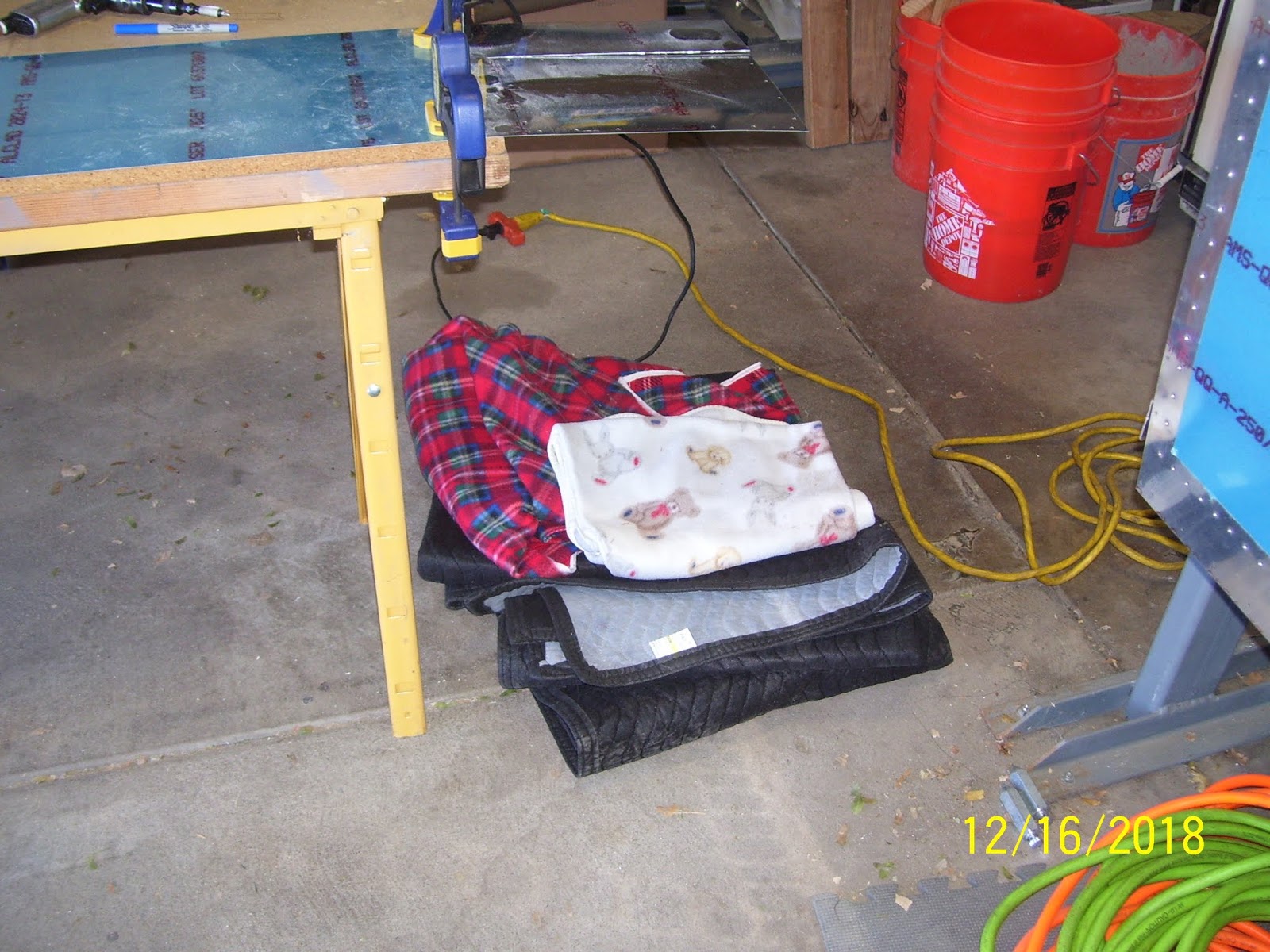
My original plan for preserving the integrity of the part and keeping it from being damaged after it fell away from the rest of the sheet was to allow it to come to a soft landing on some blankets that I strategically placed under the part on the floor as shown below:
And here is the corner of the edge that got mucked up a bit after I tried to catch it with one hand as it began to bend away from the sheet when I got about an inch away from the corner with the cutoff wheel.
After I separated the part from the sheet, next stop was over to the scotch brite wheel for many edge-smoothing and trimming sessions. Here is  shot of the part immediately after removing it from the sheet with the cutoff wheel. Its not real hard to see where the nice clean factory-cut edges are and where I rough-cut them with the cutoff wheel.

I was so glad I was able to use that tool instead of resorting to files and sandpaper like I had to do on the LE skin, which is way to big and cumbersome to be able to use the wheel. After the initial corner forming and edge smoothing and straightening, next came the long painful process of trial fitting the part with the LE. Fr some unknown reason I decided to start with the top side, not quite knowing what I was going to do once I got to the point where it wraps around the front and on the bottom side. I was pleasantly shocked to see that most of the rear edge clecoes and the sides were aligned quite nicely. the left edge was laying down very nicely next to the edge of the LE skin on that side, and the rough cut edge was overlapping the other side, but not by much. 
Next is a series of pics after I got the corners shaped enough to allow them to sit flush on both sides. There are some gaps, but as I mentioned before, this may be OK to allow for layers of primer, paint and sealer when that day comes. All I was interested in right now was the general overall fit f the part so that it would lay flush on the surface of the subskin, and as close to the edges as possible, with all screw holes clecoed in place and aligned. If I could achieve that on attempt one I would be very happy. 


With the top side fitted, I removed the part from the top and moved it to the bottom, where I repeated the same fitting, scotch brite, refitting, cleoeing exercise that I performed on the top side:
On the bottom right rear corner you can see the one single hole that is not clecoed. That turned out to be the ONLY hole that was not properly aligned with the hole in the subskin. Unfortunately there is nothing I can do to fix that problem other than mark and drill a new hole in a new part, meaning that this one is "toast" because of that issue alone, let alone any of the other edge gap issues that also exist. Unfortunately the misalignment is so bad that I cannot just fix it when I up-drill the #30 hole to the #19 hole, so that means I whole new part has to be fabricated. Here is a blurry close up of that hole where you can just see how badly misaligned it is.

And here you can see the gapping on the left side of the bottom edge. The pic makes it looks much worse than it really is, but it is quite noticeable, compared to how the other edges are lining up with the LE skin. 
And here are a couple more showing the gap along the bottom and right side edges of the bottom portion of the part:

At some point I decided that instead of marking up a second part I was going to go ahead and check the fit of everything AFTER wrapping the skin from bottom to top and securing it on both sides to see how well that worked out. ONce the edges on either side, the corners, and the rear-most edges were proven to allow the part to rest correctly against the subskin on both sides without any overlapping or interference with the LE skin, I started out with everything clecoed in place on the bottom, and then just used my hands to easily bend the aluminum around the front and over the top side. TO my amazement everything laid down on the subskin as expected. I clecoed the holes in progression from the bottom side up, and then the top side down, secring the edges as each hole lined up with the hole in the subskin. It fit like a glove.


So it was looking good until I checked the following area. Just as I had mentioned before when I noticed the LE skin does not quite sit completely flush with the subskin in the very front, right where it curves. The inboard side of the LE fits a little better than the outboard side. Well, true to form, the part, just like the file folder template, laid down very nicely on the top of the subskin, but there is a complete mismatch where the LE skin curves around, and the new part was very noticeably mis-aligned with the curvature of the LE skin.


As I also previously stated, my plan to address this in the easiest manner is to build the removeable part up with fiberglass or carbon fiber so that it matches the contour of curvature on either side of the LE. SO that will take a little bit of some unplanned work to take care of that little issue. It is better to fic this problem that way, so that the part lies flush against the subskin, than to try to adjust screw hole locations or skin size to get the right "bend" in everything. So, the MOST important thing about this is that one way or the other, the removeable section WILL properly align with the contour of the rest of the LE when it is all finished up. There was already plenty of other fiberglass work to do when I add the lighted gun ports to the front of this part, and so now that it looks like I will also need to do some composite work on the "normal" part with no gun ports, I guess that will just be more practice opportunities for me to get it right before I mess with the "funner" stuff.

The last pic I took today is just to show that from a distance, except for all the new clecoes in all the new holes for everything, it looks just like it used to look before all the measuring and cutting took place. When all those hole are riveted in place it will even more like the regular old un-modified LE that it used to be. So, just as with everything else on this project, I feel 90% done with all this, with 90% more left to go. But at least most o the hard work is done, until I get around to doing it all over again for the right wing.


All for now. KPR 


Saturday, December 15, 2018

Finished the file folder template, match drilled the #30 screw holes, Transfered the template to the metal

A productive day in the shop today, even though I still don't have much to show for it. I decided to prepare a new file folder using the same measurements as before - 11.75 inches long and 7 13/16 inches wide, since the first one got trimmed to the point that it was no longer a very good match. This time I used a pencil with a very fine point for all the measurements, and I was a bit more precise in my measurements and line drawing, etc. The new file folder template came out pretty good, and was a precise match for the space on the top side of the LE. However, when I taped it all down, I was coming up a bit short on the rear edge of the bottom side of the template. But side-to-side and in the corners everything seemed to be aligned pretty well. I did not worry too much about the short length issue because I knew that the bending of the metal will stretch it just a bit, and I am also going to cut the metal a bit larger than the template, and then scotch brite the edges and sand it  down to the precise fit that I need. SO the edges will be exactly how I need them when it is all said and done. Here is the new template re-taped in place on the top side of the LE:
And next is the bottom side. You can see the gap on the bottom left edge near the corner. 
You can also see some of the screw holes that I have "hand drilled" by using a #30 drill bit and my hands and fingers to align it from the inside of the LE through the outer rib, locating the #30 drilled holes in the subskin, and then turning the drill bit just enough to poke the hole through the file folder template. Here is the view of how I did this from the inside. it wasn't too difficult to locate and drill most of the holes, but the last 2 or 3 tested my creative ability to contort my arms, hands, fingers, and body to get the drill bit into the correct holes.
Of course when I drilled the hole through the template  aligned the drill bit as best I could so that it was going straight through the hole in the subskin, which is not the way it is positioned left free-standing through the hole so I could take the picture.. This actually turned out better than I thought it would, and seemed to result in all the holes being properly transferred to the template.

Here is a closeup of what it looks like when the drill bit poked through the file folder template. I used my finger on one hand to apply opposing force on the paper template from the outside, while I used my fingers on my other hand to turn the drill bit from the inside - quite the parlor trick if I do say so myself.
I continued this process until all the screw holes in the subskin were transferred to the template, then I removed the template frome the LE to continue with the rest of the  steps to transfer the shape and hole locations to the .025 T3 2024 aluminum sheet that I had purchased from Vans long ago.
Next I performed yet another not-quite-so-orthodox procedure to transfer the screw holes to the aluminum sheet as shown below. I used the hand-held drill bit once again after taping the template to the aluminum sheet to "mark" the metal through each of the template's screw holes to drill a small amount of material to mark the locations. I also aligned two of the outer edges of the metal with two of the edges of the template, to reduce the amount of work required to cut the part out of the metal by only needing to cut along two of the 4 edges of the part. I did check the metal first to ensure that the two existing edges were square and straight with each other.
All the screw holes locations were marked after I removed the template from the aluminum sheet:
So far so good. I removed enough material with the drill bit to ensure that it would find its center once I was ready to actually drill each hole. I should also mention that the grain of the metal needed to be aligned similar to the rest of the LE skin, so the orientation of the grain, which parallels the magenta printed info on the sheet, was important to note while positioning the template on the metal sheet. You also have to make sure yo specify how you want it cut when you order it from Vans, so specifying the grain direction should always be done, in addition to the other dimensions and the thickness.

Next was setting the sheet up on the drill boards, clamping everything down, and final drilling all the screw holes to #30. Once I know that this is working out well, the #30 holes in this part and in the subskin will be final drilled to #19, and dimpled for the #8 screws that will be inserted in these holes to secure it to the subskin.

I drilled the holes without the template in place with the protective vinyl covering still in place, clecoing the metal to the drill board as I went. Then I removed the vinyl covering from the metal, deburred the holes on both sides of the sheet, and clecoed the template back onto the metal so that I could redraw the outline of the edges again on bare metal. Previously the lines were drawn on the vinyl covering, so when that got removed, I had to redraw the edges again on the bare metal. Here is the template clecoed onto the metal sheet and the drill board so I could redraw the edges on the metal sheet.
And here is a final shot of the metal with all the #30 holes drilled and deburred, and the vinyl removed, and the lines redrawn. Next steps for tomorrow will be to cut out the part from the metal, trim down the edges, and start form fitting and trimming the part until it fits nicely into the cutout on the LE skin. Before I do that, however, I may decide to go ahead and make another metal part with the edge dimensions but no screw holes. The real trick to this is going to be if the screw holes are in the exact position that is needed to ensure that the part lies completely flush and tight with the rest of the LE skin. If it does not I will have to reposition the screw holes a bit. SO this may take 2 or 3 or more iterations before I have it exactly right.


If the holes are right and the fit is right, the next step is to cleco it all in place and final drill the #30 holes to #19, debur and dimple them in the part and the subskin, which of course also means removing and disassembling the LE once again. Getting there (I hope).

KPR


Tuesday, December 11, 2018

Making the Paper Template for the removeabe LE section

So tonight I took yet another file folder, took some measurements, drew some lines, used the access panel to trace the radiused corners, trimmed it to size, and then fit it onto the LE and taped it into place. It looks like the edges from side to side are fairly consistent at 7 and 13/16ths inches, and the length from the top of the LE wrapping around to the bottom side is about 11 and 3/4 inches.

Unfortunately I went into this exercise believing that the file folder was a god choice because they should be square, but I think this new box of file folders I bought from Sam's Club are anything but. I used my metal square and tried my best to ensure that the edges were square, but this proved to be a challenge for me this evening for some reason.

So, I think I am going to opt for a better template material that has stiffer and straighter paper; perhaps some poster board or something like that.

I also determined that I can deal with the gap on the outboard side between the subskin and the outer LE skin by building up the removeable skin with flox or some other fiberglass combo if necessary, so that it will be flush with the outer LE skin, and so I can worry about that later. For now, getting the side and end measurements of the removeable section s the most important thing to do. No pics tonight. The fit using the file folder was close but not close enough for my liking, and although that method worked fine for marking the cut lines on the outer skin, this time I need precise measurements that very closely match the same edge distances after cutting that section away. Due to differences in the thickness of the Sharpee line used to draw the line and where exactly I filed and sanded the edge to may cause slight variations in the actual measurement. So this may take some fine tuning before I get a template that I think will work properly.

I also determined that marking the position of the screw holes is going to be a challenge as well. As much as I would like to think that I marked and drilled all the screw holes in the exact measured spot, the reality is that only a CNC machine is capable of that, and all my holes were measured and marked by hand. If my center punch was off just a bit or my drill bit started the hole just a bit off, the center of each screw hole will not be exactly where I think it is. SO I can't just rely on those measurements and transfer them to the template. These screw holes have to secure this part very precisely, so they need to be located on the template based where they are actually located, not by the planned measurement. I'll have to think about how to do that accurately once I get the template sized correctly. It's times like these when I wish I had  CNC machine to take the guesswork out of this.

Monday, December 10, 2018

Subskin prep - Drilled and Dimpled Remaining nut plate rivet attach holes and Reassembled the LE

Today was a busy day at the factory, but for the amount of progress I made today you would probably not believe me. I finished sanding the edges of the cutout section of the LE skin smooth and straight, and used the combination of my pneumatic rivet squeezer and C-Frame tools to dimple all remaining #40 nut plate rivet attach holes on the subskin. I had to switch from my flange yoke to the standard 3 inch yoke to be able to reach all the rivet holes along each side of the subskin, and this worked out nicely. I had to use the C-Frame to reach most of the rear-most rivet holes on both sides of the subskin, and this also worked out well.

Unfortunately I had to use the #30 cleco method to secure the nut plate to the subskin so that I could align and drill the holes for each nutplate on the top side of the subskin, just as I had previously done on the bottom side. Just as before, I had trouble keeping the line of rivet holes in alignment with other straight edges, and some of them got a bit slanted. As I stated before, these holes are just for the rivets that attach each nut plate to the subskin, so the MOST important hole is actually the center hole where the screw will be inserted, and not the rivet holes.

I used the same technique to mark the alignment of the rivet holes on the top as I did  on the bottom, by placing a straight edge along the center line of each #30 screw hole and drawing short lines on either side of each hole that I used to align the rivet holes of the nutplate after it was clecoed to the subskin through the screw hole.


I drew the lines along the sides on the outer side of the skin, and drew the lines for rear nut plate holes on the inside of the skin, just as before. As shown from the pic above, I also came up with a different clamping and prep method of drilling these rivet holes. This time I really did not care so much about trying to rig up something so that I could clecoe the nutplate in plate as shown above, and then ensure that I was drilling each rivet hole into a piece of wood. I reasoned that any slag or burr on the holes would be removed by my deburring tool afterward, and so this time I chose NOT to waste a substantial amount of time coming up with ridiculous ways to ensure I could drill each hole into a piece of lousy wood. This worked out fine, except for the slight shifting of the nutplate because the clecoe just does not apply enough force to keep the drill from moving the nut plate around. SO I much prefer using the nut plate jig which prevents this from happening, but since I was not yet ready to drill the #30 hole to a #19 hole yet, which the jig uses as a pilot hole, I could not use the jig tool.

I used my 4x4 clamping blocks to provide some height to allow the cleco mounted from the underside as shown in the next photos to clear the table and saw horse ends, and the next pic shows how I clecoed the first hole after it was drilled, which keeps the second hole from moving around as well, so that both rivet holes are in alignment with each other.


As each set of rivet holes was drilled I detached the nut plate and moved it to the next hole and re-clecoed it in place, and repositioned and reclamped the subskin as necessary to retain some rigitidy in the subskin near the nut plate locations so the drill would not slip or cause the skin to warp and the hole to become mis-aligned. Here is the series of pics as I continued to drill each set of nut plate holes along the sides:


With the sides done it was time to drill the rear nutplate hole. I had to flip the subskin over and reposition and reclamp it once again. I was able to use the edge of the table to help position the skin so that the clecoe underneath butts up against the edge, keeping the skin nice and stiff while drilling.


The last pic above actually shows the holes after I dimpled them. The mot important thing to call attention to here is that I have NOT yet final drilled the screw holes to the proper size because I need to make a template first so that I can fabricate a properly sized part that will replace the cutout section in the skin. I cannot final drill the screw holes to #19 and dimple them for a #8 screw until the template has been created and at least 1 or 2 .025 removeable LE skin sections have been fabricated and fitted in place. To do that I need the screw holes to remain at #30 for now. 

Next I had a bit more cutting, filing and sanding to do on the subskin. A long time ago I had marked the location where the hole for the tie down ring is located by tracing the hole I had already drilled in the LE skin onto the subskin, which, until today, had been covering up that hole. I used the cut off wheel o n the Dremel tool to carefully cut away the metal in this area, staying just OUTSIDE the drawn lines so that  could ensure that the subskin would have enough clearance to screw in the tie down ring. Here is the pic of that after filing, sanding, and rounding all corners was completed:
With most all of the subskin prep work done, it was time to reassemble the LE for what I hope will be the second-to-the-last time before it goes together permanently. the subskin was attached first using all the rivet holes that are not part of a rib flange hole. This gets the subskin in the proper position for the ribs. Then the two inboard-most ribs are clecoed to the subskin and outer LE skin. This process always takes some work because the ribs are a very right fit in this area due to the thickness of the subskin. Again, the goal of all this was to reassemble the LE with the newly cutout section in the skin that exposes the subskin that will be used to attach the removeable LE section.

Here is a series of pics I took to show the fit of the LE and subskin after remounting it all back on the wing spar again. Overall I was pleased, but the problem that I feared and mentioned in a previous post is exactly what I encountered. The outboard are of the cutout section of the LE skin shows a bit of a gap between the subskin and the outer LE skin, whereas the inboard section seems to be draped over the subskin fairly well. This will make fitting the removeable part a bit of  a challenge, but we'll see how that goes. I am not overly concerned about the gap because I think the rib in that area combined with the subskin provides more than enough support to keep the LE from deforming in any way as a result of this gap. In other aircraft designs, such as the Sonex for example, I know that their ribs do not even wrap around the contour of the LE skin. Instead, they stop well short of the very front of the skin so that NONE of the ribs have any rounded contour that wraps around the LE at all, leaving a void between the rib and the very front part of the LE skin.

As long as the shape of the front of the LE skin remains consistent across its entire span I do not see a problem with this. I think this will occur because the rest of the LE outer skin is stressed, so it retains most of its shape due to the tension of the bend that is force-ably wrapped around the top and bottom flanges of each LE rib.

First pic is the top side of the LE with the subskin now showing through:
Next are the inboard and outboard curves of the front of the LE skin showing the gap I mentioned between the LE skin and the subskin  on the outboard section. Both pics are takne from the top side of the LE:


The next set of pics is the same series taken from the bottom side of the LE


And finally 2 pics that show the clearance of the tie down ring hole through both the outer LE skin and the subsin after trimming it away from the subskin. Looks pretty good to me, but I may decide to wien both of the holes a bit to make certain that stresses placed on the ring from high winds etc. will not start contacting the edges of the LE sin in this area. The ring can be screwed in and out with ease.

So this was a day that was very long in the making. I had to wait 2 weeks for it to warm up enough in the garage to get to this point. took about 3 hours or so to do everything described in this post. Next steps are to make the file folder template and fit it to the cutout section of the LE, mark and drill the #30 screw hole locations in the paper template with the LE firmly mounted back on the wing spar, remove the template and use it to trace the new removable section of the LE onto a piece of .025 aluminum. I may decide to go buy some Home Depot grade stuff to practice on until I am certain that I have the outline of the part measured, cut, and formed correctly. My concern now will be what I need to do to make the curved front end of the removeable section match the curvature of the inboard and outboard outer LE skin. Not sure if I will need to apply some shims due to the gap, or if I will be able to pre-stress the removeable section similar to the outer LE skin so that it will retain its shape with the rest of the LE skin. Time will tell on that one.  Hopefully I will be able to get to that point this week since the weather is finally supposed to be warmer.