Thursday, March 11, 2021

Making a Rotisserie for the Fuselage - Part 4

 With new hardware to play with, the next steps were to remove the front wheels of the engine stand, determine the height of some wood to replace the front wheels to keep the mast of the engine mount level with the ground, and start the process of cutting the 1x1 steel angle to size, and drill the first set of holes in one end of each angle.

Here is a pic of the stand with the wheels off. I first used a piece of 2x wood that I cut long ago to use as a form block for bending the mounting plate for the LE mod, and a piece of 2/8 inch thick plywood. That seemed to put the mast back to level when I checked it with my torpedo level.


Then I had the idea to put the mounting bracket on the stand and recheck the level. What I discovered was that the mounting bracket has a lot of play when mounted in the cylinder at the top of the stand, adn when I put the level on the actual mounting bracket that everything would be attached to I found that mast was no longer level and was indicating a bit too high. Then I found a piece of 1/4 inch plywood that was from the top of the crate that my wing kit came in years ago, and this seemed to set everything back to level again with the mounting bracket installed on the stand. Now I just need to cut the wood pieces to size and mount those to the stand using more nuts and bolts.


With that figured out, just prior to removing the front wheels from the stand I was wheeling it around in the garage, and I noticed that only 2 of the 4 wheels were making contact with the floor. A closer inspection revealed that that cross bar that serves as the front axle for the front wheels was at the angle to the rest of the frame. This means that some of the metal and/or the welds of various pieces were not done very well to ensure that the mount points for the wheels would be square to each other. This also means that when the fuselage is mounted to the frame it would not be sitting square but a bit lop sided in the front. I just could not allow that to happen, so my solution was to get out my sledge hammer to see if I could coax the front axle to be a bit more square to the rest of the frame. As I pounded on one side or the other I noticed that the square post was being forced into the corner of the frame. Either way this allowed the front axle to reposition itself so it was a bit more square to the rest of the frame, so I was satisfied with that. 

That exercise just further convinced me that welding is totally an imprecise, unreliable method of joinng metal together. I am also sure that the fact that it came from China has something to do with that as well. You get what you pay for I guess. These next pics attempt to show the angle of the front axel when compared to the rear axel of the stand. it is hard to tell but there is small when you look at the front axel and how it aligns with the axel in the rear of the frame. I just wanted to make certain that the stand would not wobble with the front wheels removed.


The next step was to find the exact center of the firewall at the front of the fuselage. The idea is that the exact center of the firewall is also where the exact center of the mounting bracket should be located. This ensures that the width and height of the front of the fuselage when mounted on the stand will allow the fuselage to be rotated so that it will clear the bottom square metal frame of the stand. I will have to get my figures posted tomorrow, but I used my flexible 2 foot long metal ruler and a tape measure to find the widest and highest points of the firewall, found the half way point and marked it with a Sharpee on the firewall. I believe those measurements for the half way points were 18 and 1/8 inches wide and 15 and 1/16th inches high I ran the tape measure from end to end to find the widest or highest point of the firewall. As shown in the following pics, it ran through the exact centers of some rivets in the firewall. 


Fitting the mounting plate so that it is centered with the center of the firewall ensures even clearance of the fuselage when right side up, upside down, or to either side as needed. 

With that out of the way the next step was to start cutting and drilling the holes in the steel angles that will serve as the extended arms that connect the mounting plate to the spider arms on each corner of the firewall. Since 1/2 inch AN bolts seem to fit rather well in the precut slots and holes in the mounting brackets, I decided to drill 1/2 inch holes on both ends of all 4 of the angles as well. This becomes a bit of a challenge when you consider that the 1x1 inch angles are 1/8 inch thick. This means that you only have 7/8 of an inch to drill a 1/2 inch hole. 

I also had to ultimately decide where along the flange I would drill each hole. I decided to start with one inch inboard of the end of the angle. The next series of pics shows how I marked and set each angle in the drill press clamp. The drill press did allow me to drill very accurately placed holes in the angle. The clamp and the wood allowed me to secure the angle in the vise and line up my 1/2 inch drill bit.


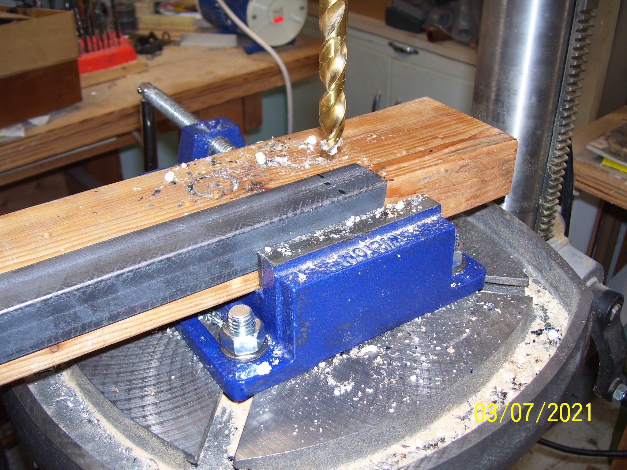
I should also mention that before all this drilling I cut the angles in half as a starting point. So each angle is currently 24 inches long. I used my sawzall with a metal cutting blade. It made quick work of that. I then used my grinder to remove any sharp burrs on the cut edge. Then, before you start drilling holes, you also have to decide how you wan tot position the angles - with the perpendicular flanges faced outward or inward. from the mounting surfaces. In the pics you can see I chose to have them placed inboard - no real reason, but you have to decide how you want to position them so you know which side to drill the mounting holes for the bolts.

After the first 4 holes were drilled I mounted each angle to the mounting flange of the engine stand for a trial fit. 


After this trial fitting, I discovered that the AN8-11A bolts I ordered were just a little short for the 3/8 inch thick mounting flange and the 1/8 inch thick angle. SO I ordered some An8-12A and 13A bolts that arrived today that should fit the assembly a bit better. The issue with the hardware is the length. It cannot be longer the thickness of the spider lugs and the angles. I was concerned about this when mounting the bolt so that bolt threads are facing the firewall and threatening to get a little to close to it after they are tightened down. After reviewing a few posts from other builders I saw that this is much less of an issue if you mount the bolt so that the head is on the side closest to the firewall, and the threads and  bolt shank are on the opposite side and never at risk for puncturing the firewall. 

The last pic is the 3/4 inch wrenches I used to mount the bolts. When the weather improves again I will replace the AN8-11A bolts with the longer ones, and begin the process of reducing the size of each angle to its final size when I fit the other end of them to the  spiders.


Monday, March 1, 2021

Rotisserie Hardware Finally Arrives

 I finally got my hardware that I ordered about a month ago. COVID sucks. Bad weather - the worst snow storm of the year that the news media said would only amount to 5 inches that turned into 15 - also sucks. Then there is UPS, but I digress. I guess I should just be thankful that I got anything at all.

The list is as follows:

50  NAS1352-08-8P 1/2 inch socket head cap screws - to replace the Vans pan head screws used to attach the access plate to the inboard fuel tank rib to make it easier to service/remove/replace with the tank mounted on the plane. 

50 AN960-8 thick washers for the above screws

50 AN960-8L thin washers in case a thin washer is required for proper screw depth

4 AN7-11A 7/16th inch thick bolts to potentially replace the metric bolts that came with the engine stand

4 AN8-11a 1/2 inch thick bolts that should fit the hole in each spider arm a bit better than the AN7s will. I bought both so I could choose which one I would like to use.

4 AN 960-716 thick washers for the 7/16th inch bolts

4 AN 960-716L thin washers in case those are needed for proper fit.

4 AN 960-816 thick washers for the 1/2 inch bolts

4 AN 960-816L thin washers

4 AN3-7A 3/16th inch bolts to firmly attach the angle to each spider arm I already have enough washers and bolts from my previous order for these bolts so I did not need to order any more of those.

4 AN365-720A Nylon Lock nuts for the 7/16th inch bolts

4 AN365-820A Nylon Lock nuts for the 1/2 inch bolts

The primer had to be back ordered - apparently until April sometime. Oh well. The plus side to that is that I will be reasonably assured that the 2 year shelf life will still be in tact, instead of already being expired or close to it as usually happens. Here is a pic of the hardware:


The steel angle will be attached to each spider arm, and while the big 1/2 inch sized hole allows for a large heavy bolt to be torqued down against both parts, there is still a possibility that the parts could shift while rotating the fuselage, and that could spell disaster. TO ensure that this does not happen, one more hole needs to be drilled into the spider arm in between the lug on one end and large bolt hole on the other, so that one more bolt can be added to secure the angle to the arm and prevent it from turning. Most have used a small AN3 bolt for this, and at 122,000 psi tensile strength (AN hardware specs) I am not concerned about shearing any of the smaller AN3 bolts used in this assembly.  

The next step was to set up the drill press to drill the additional hole in each spider arm, and then I can use that hole as a guide to match drill the hole in the angles once I cut those to size. I used a 3/16th inch metal drill bit, and set the belts on my drill press to 990 rpm per the recommended setting for drilling mild steel. this is much slower than the 3100 rpm commonly used for wood. Drilling metal builds up heat very fast, so keeping the drill bit and the work piece as cool as possible is important. 


I measured the distance between the edge of the lug and the edge of the bolt hole and more or less split the difference, so that the new hole would be about half way between the edges of both holes. This turned out to be  about 1 11/16th inches or so.

The white powder in the following pics is Boe-lube that I sprinkled on the drill bit and in the hole of the spider arm. It is a Boeing product that is very much like candle wax but probably has some other stuff in it. It acts as a coolant and lubricant and is highly recommended when drilling into metal.

I used the straight edges of pieces of masking tape and a sharpee to mark the center point of each each hole, then marked it with my center punch so that the drill bit would seat properly. Then ot was just a matter of playing the drill table and vise to get it all lined up properly.


The holes in all 4 arms came out pretty well, and the drill bit plowed through the steel with ease as I slowly lowered the quill. You drill a little and then back it off, then add some more boelube if necessary, and do it again until the hole is drilled completely. The above pic was the first hole that I did not line up quite right, so it is a little off center. The other 3 are much better. If I need to drill another hole in this one later on I will do that.

And finally a trial fit with an AN3 bolt just to check the fit in the new hole.


This is not the same bolt I will use to attach the angle to each arm - it was just handy so I used the super long one just to check the fit.

Finally, after I was done drilling the 4 new holes in each arm, I noted something strange on my drill press. IT has a laser unit, and on the side as shown in the next pic I noticed that the locking ring screw post that is mounted to the edge of the laser unit was slanted to one side. as I moved the quill I could see it change from being off center to moving back to straight vertical. As I repeated this several times I noticed that it was the entire laser unit that was moving. There is a set screw in the back of the unit that secures it to the drill assembly. Sure enough, as I put my hand on either side of it I discovered I could move it from side to side. Not good. 

So I grabbed an allan wrench and tightened it down a bit and verified it no longer moved from side to side. I had been wondering why my laser lines always seemed to be off target during my latest drilling sessions, and now I know why. If you look just below the silver part of the press where the center of the laser unit is positioned, at the small black flange just above it, you will see that it is at an angle. The laser unit should be sitting in this flange so that it is completely level, and obviously this is not the case. A couple turns of the clamping screw took care of that problem. I guess it had come loose after many years of vibration and use. Glad I solved that problem.


Next steps are to cut the angles to size and drill the required holes on both sides. then I will finally be able to position the center plate, mount each of the arms, and try this thing out.

KPR