So I was all set to slam out the rest of the rudder last weekend. Problem is I have a son graduating frm High School in two months, and the wife wants to throw a nice party. That means that the house and the yard needs some TLC. So I ended up getting started on just a few of the projects - painting the interior of the house, putting in a tiled entry way, laying down hard wood floors, etc. Just a few "easy" and non-time consuming tasks to take care of......
Just had to bite the bullet on this I guess. So now I am in rapid honey-do completion mode until these projects get done. Tiled entry way should take no longer than this weekend, and the hardwood floors may take the next couple of weeks off and on. Somewhere in that time frame I expect to finish the rudder.
I did manage to get the bottom rib divots smoothed out to my satisfactions. I ended up using 220 grit aluminum oxide sand paper wrapped around an a 1/8 inch dowel to get in there and fix the divots without removing too much material on the rib. I also cut some newspaper to size to mask the inside and outside of the rudder skin so I can finish prepping and priming the ends of each skin. If I get the tile floor done before the weekend I will take a break and see if I can't get to a point where I am slamming rivets again.
My buddy Ron Duren should have received his fuselage kit today for his RV7. Jealous, jealous, jealous I am....
Wednesday, March 23, 2011
Wednesday, March 16, 2011
250 hours on the hobbs - new tools and more rudder work
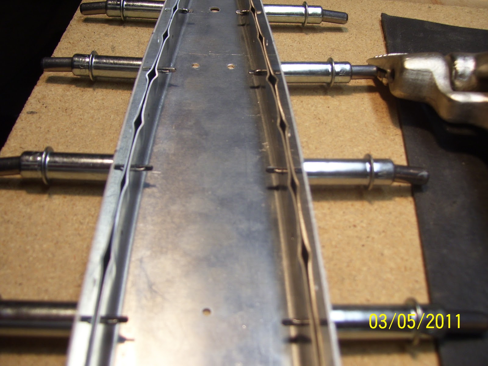
Pic of the new #10 dimple dies for the screwa thagt will hold the coun terweight inside the rudder tip rib:

Rib is in the background and already dimpled. Here is one with the screws in place:


And another that shows the lead weight that will be mounted in this space, as well as the hardware called out in the plans, and the number 10 countersink bit that I will need to use to countersink the lead weight so that it will accept the dimples in the rib.Will also need to remove small amounts of the lead where the other rivets along sides will be set. This is also normal. The right amount of weight will actually be determined before painting and after painting, and also after the fiberglass tips are installed, which I will be doing later in the build.


Here is the difference between the standard sized female dimple dies and the the reduced diameter one - at least 1/16th of an inch I would say:


The one on the bottom is a rivet cutter - used if you need to trim rivets to a more correct size to prevent folding it over if it is too long. Hopefully tomorrow I can prep the rudder skin and prime it a bit more and finish dimpling it as well. Getting there.........
Rudder frame parts mostly cleaned, scuffed, and dimpled. Oh, and look, there is the infamous bottom rib that I have been slaving away at for the past two days to remove the divets that I created through my own stupidity. I can't seem to get any good pics of the divets, but I will post a couple of pics so maybe you can finally see what I am talking about.
 The divets are in the absdolute worst place on the entire rib - very hard to get fingers or tools in there to get right at the trouble spot. You just have to be persistent and don't stop until you know within your self that the part has been repaired successfully. The divets are just underneath each the last several dimples of the trailing edge of the rib in the following pics.


SO you new builders out there reading this stuff, please, take my advice, as soon as you receive your yokes for your squeezer and any other close quarter tool that you may order that contains a dimple die in the frame or welded to the tip of some tool or pliers or whatever - fire up your grinder IMMEDIATELY and trim these tools down, as they will only cause you grief and stress later on if you do not do this.Also remember to hold true to yourself and to adhere to the rule that if the part does not quite sit or fit right, keep working on it until it does. Above all, I hope you learn from my mistakes. There - the rest of you have been warned!

Rib is in the background and already dimpled. Here is one with the screws in place:

And one of the other side showing the dimples it created. I thought they were quite large until I fropped the screw in there - fits like a glove almost:

And another that shows the lead weight that will be mounted in this space, as well as the hardware called out in the plans, and the number 10 countersink bit that I will need to use to countersink the lead weight so that it will accept the dimples in the rib.Will also need to remove small amounts of the lead where the other rivets along sides will be set. This is also normal. The right amount of weight will actually be determined before painting and after painting, and also after the fiberglass tips are installed, which I will be doing later in the build.

Now on to the grinding of the yoke and my close quarter dimpling tools:
Apparently there are some problems with being able to up load pics to the blog so I may have to call it an night. I basically got back on scuffing out the divets in the bottom rib as best I could, and I finished grinding down more of the yoke and the close quarter tool after fitting my new reduced diameter female dimple dies onto the yok to check the clearance. I should have no more problems with divets being gouged into my parts due to excessively oversized parts or tools.


Here is the difference between the standard sized female dimple dies and the the reduced diameter one - at least 1/16th of an inch I would say:

And this one of the close quarter dimpling tool

I used both sides of my grinder- the normal side on the left for grinding away the steel a little at a time in a uniform manner, and the scotch brite wheel on the right for polishing everything up and removing any sharp edges left by the grinder. Worked very well as long as you remember to only remove small portions of metal at a time and then check your work constantly.

And the new tools that arrived today:

The one on the bottom is a rivet cutter - used if you need to trim rivets to a more correct size to prevent folding it over if it is too long. Hopefully tomorrow I can prep the rudder skin and prime it a bit more and finish dimpling it as well. Getting there.........
Rudder frame parts mostly cleaned, scuffed, and dimpled. Oh, and look, there is the infamous bottom rib that I have been slaving away at for the past two days to remove the divets that I created through my own stupidity. I can't seem to get any good pics of the divets, but I will post a couple of pics so maybe you can finally see what I am talking about.


SO you new builders out there reading this stuff, please, take my advice, as soon as you receive your yokes for your squeezer and any other close quarter tool that you may order that contains a dimple die in the frame or welded to the tip of some tool or pliers or whatever - fire up your grinder IMMEDIATELY and trim these tools down, as they will only cause you grief and stress later on if you do not do this.Also remember to hold true to yourself and to adhere to the rule that if the part does not quite sit or fit right, keep working on it until it does. Above all, I hope you learn from my mistakes. There - the rest of you have been warned!
Tuesday, March 15, 2011
Summing up the last couple of days - Challenging - More tools on order
So no pics just yet, but coming..... Over the past couple of days I have been cleaning and prepping aluminum and dimpling the frame for the rudder. Finally had to sucumb to the need to grind down my 3 inch yoke for my squeezer. As so many others have already experienced before me, you run into problems dimpling the bottom rib of the rudder - NOT the much smaller tip rib mind you, which seems to have enough clearance between the bend line of the flange and the rivet holes, but the much larger, much wider bottom rib ( you know, the one I had to replace a while back). Before I go on, I blame Vans for all this ridiculousness. Why in the hell can't they form a part with sufficient clearance for most of the common tools being used out there today. Just plain ridiculous...
Anyway, the holes I dimpled in both ribs with the pneumatic squeezer and the newly ground down yoke seemed to go OK, but eventually you get down to the last 4 or 5 holes toward the trailing edge of each rib, adn there is not enough room for the squeezer to dimple those holes. So in comes the close quarter dimpling tool I have been raving about so much in past posts.
SO I began thinking that since this is a tool designed for close quarters work, surely it must have enough clearance built into it so as to avoid interfering with the web of the rib, right? Boy was I wrong, and I did not find out until after I had dimpled 6 holes in the bottom rib. I did notice that the flange did not seem to want to sit quite level on the tool, but I thought it was close enough, so I ignored the warning sign.
Anyway, I ended up putting some very small but very pronounced 1/16th inch divets in the web of the rib, in line with each dimple. This was caused by the front edge of the steel frame of the tool, which houses the female dimple dye, scraping against the web of the rib while I created the dimple with the rivet gun.
So I spent most of the rest of this evening sanding out the divets - man is that hard - they are right above the bend line of the rib flange, adjacent to the dimple. I had to cut small pieces of 220 aluminum oxide sand paper, fold them up as small as I could, and use my thumbs to grind down the divets. It's too risky to try putting a small dremel grinding tool in there, and both of my small scotch brite wheels are just a tad too large to fit down in that area without mucking up other things. Man are my thumbs worn down from all that sanding. I managed to get about 3 of them soothed out to the point where I am satisfied that there are no stress risers, but I still have 3 more to do tomorrow before I can continue with other tasks.
I ground down the tip of the close quarter dimpling tool and all is well now - no more divets on the last 5 holes of the rib.
As for tools, I ordered a bunch more dimple dies from Cleaveland tools - a set of 3/32 tank dimple dies, a 3/32 and 1/8 inch reduced diameter female die, and a Set for a #10 screw, which is needed for the dimples that will house the flush head of a #10 screw that will attach the lead counterweight to the inside of the tip rib of the rudder. I also ordered a rivet cuttter because I have it on good authority from Steve Riffe's posts on his builders log that many of the rivets used to set the parts of the rudder frame are slightly long, and need to be trimmed down just a bit to avoid problems when squeezing the rivets. I purchased the reduced diameter female dimple dies because they were only 18 bucks a piece, and Cleaveland did all the work so I won't have to. Others are taking standard sized dimple dies adn grinding them down. I ahve had my fill of grinding down tools at this point.
Hopefully I will get the skin primed and dimpled tomorrow.
Sunday, March 13, 2011
Cranking away on the rudder skeleton preparation
Back to 3D mode - drilling, deburring, dimpling, followed by cleaning, scuffing, more cleaning, and finally priming. I was so busy yesterday that I did not even get any pics of the whole thing clecoed together while I finished match drilling the rest of the parts to the skin. I have since taken everything apart again. I will be happy if I can get to the point where everything is dimpled and primed. Dimpled probably - primed may be a bit of a stretch, but we'll see. I may have to ground down my dimple dyes and one end of my yoke according to several other posts from other builders that are on this phase of the build, but hopefully that won't take too long to do. This is needed because the flanges on some of the control surface ribs are not wide enough for the tools, so sometimes you just have to make some modifications to all those expensive tools that you purchase, to ensure that you have the right tool for the job.
I'll post more pics later today.
I'll post more pics later today.
Saturday, March 12, 2011
Bottom Rudder Assembly pics - Hole in Forward RIb Flange Drilled Out
And now for some pics as promised. Bottom rudder assembly all clecoed in place. The rib, the front spar, the HS 710 Support bracket (with the large hole on the back side), and the HS405PD Angle bracket, all in place. the two small holes in the bracket are where the control cables from the rudder pedals will attach to the rudder. Sure is nice to have a viable part again so I can complete the rudder business adn move forward again.


Next is a blurry pic of the front portion of the forward spar, with the support bracket adn everything else attached. Still need to finish drilling the two holes on the bottom to finish the small shim that sits behind the bracket to level out the attach points where the rib flange butts up against the sterring bracket. All these holes need to be final drilled and deburred - will happen today. The nut plate has been installed on the wrong side for now - will probably drill the rivet holes for this while it is in that position, and then remove it and place it in the correct position behind the forward spar when everything gets riveted into place. The pic is sideways for some reason - bottom is on the left - AAARGH!

And lastly - a pic of all the different drill bits I used to step drill the hole until I got it up to 1/4 inch so I could switch to the unibit and finish drilling it up to 3/8 inches, which is the diameter of the hole needed to fit the rod end bearings into the nut plates. I checked the hole after each drilling to ensure that it was still centered and round.

Friday, March 11, 2011
Got the rib in the mail today - back to work on the rudder
This time I step drilled the hole in the flange first, by using a series of about 6 different standard type drill bits, until I got to the 1/4 inch mark. then I switched to the dreaded unibit and went very slowly to ensure I did not overdrill or distort the hole. It came out fine this time - tested hole clearance with one of the rod end bearings and it fits in there almost perfect. I decided I really do not like the unibit for precision drilling activities. I would much rather step drill the hole with normal drill bits.Unibits are OK if final hole size and postion is not too critical. I'll post pics tomorrow as it is getting late and I am tired.
Rudder frame and skins will get drilled, dimpled, and hopefully primed before the weekend is out - and maybe even some rivets...... :)
Rudder frame and skins will get drilled, dimpled, and hopefully primed before the weekend is out - and maybe even some rivets...... :)
Tuesday, March 8, 2011
Tidying Up the Blog While I wait for the Bottom Rib of the Rudder to Arrive
We have some new RV builders that are ramping up here in the local Denver Area, and so I thought I would spend some time going back in time to continue adding labels and Titles to many of my early posts when I was just getting started. So far I have completed labeling posts up through October of 2009, which is when I really got started on this adventure. It was interesting to go back and see what I had written.
As it turns out, I was also very new to the blogging art form at that time, and so many of my posts did not have titles associated with them either. I am resolving that problem as well. The label function allows me to group posts together by a common theme or category, so that those of you that are aimlessly lost in my hundreds of posts can have an easier time finding what you are really looking for. I will keep working on organizing past posts as time permits. Just click on a label or use the search function to find what you are looking for.
Hopefully I will get my part in the mail tomorrow. Weather will be warmer again also. Spring is slowly approaching, but as those of us who have lived in this state for while already know, March and April usually pack a blizzard or two into Colorado, and these are our snowiest months on average.
KPR.
Monday, March 7, 2011
236 hours on the hobbs. Drilled and deburred holes and edges.
Spent time today working around the fact that the defective bottom rib part that I received yesterday from Vans is impacting no less that the final preparation of 4 other inter-related parts. So I spent time today match drilling and deburring the holes in the forward spar flange and the support plates that will house the rod end bearings for each rudder hinge. I also drilled and deburred the counterbalance skin and the tip rib, so they are all but ready for priming. As soon as I get the bottom rib issue resolved, I can finish the rudder skeleton and move ever closer to finishing the rudder.
Probably time to start trimming stiffeners for the elevators and get that rather tedious chore out of the way as well. Then there are always the wings..... :)
Probably time to start trimming stiffeners for the elevators and get that rather tedious chore out of the way as well. Then there are always the wings..... :)
Saturday, March 5, 2011
234 hours on the hobbs. Another step forward.....and another step back.....
Man this rudder is taking a while. Hoping to get a lot done this weekend since the weather is nice, so I can do some priming of final pieces of the the rudder substructure. Since last post I palced an order from Vans for the new R710 Rudder support bracket, and a new R 704 bottom rib. Everything showed up today, so I quickly opened the package adn began checking all the parts. The R710 was in good shape, but unfortunately the R 704 bottom rib of the rudder appears to be deformed on one of the flanges. One side is obviously longer than the other, adn when you compare some measurements of the locations of the holes on each side, it is obvious that the holes are not in align ment either. Last thing I want to do is build a crooked control surface.
SO I was a little ticked off about this, but that quickly subsided, since I was at least able to start working on some other things. I will call Vans on Monday and see if I can get them to expedite another part that has been quality checked first.
Lots of pics to post this time as well - most of the time I spent since last post was on trying to resolve a problem with the R713 counter balance skin and the R 703 tip rib. The issue was trying to get the two pre-drilled holes in the front flange of the rib to line up with the holes in the counter balance skin. Honestly, after all the difficulty this posed for me, I fail to understand why Vans doesn't just leave this area un-drilled so that you can just drill both holes your self without having to do all this matching up crap.
So I'll start with the refrabrication of the R 710 support bracket. I basically trimmed the previous part down to far so that there was not enough edge distance for about 8 rivets that are driven on the sides of the rib and then into the bracket. You need a minimum of 3/16 of an inch from the edge to drive an AN426AD3 (3/32 rivet) rivet correctly.
Here is the new part with the original cut line drawn per plans from Vans, plus a new cut line with about .15 inches added to it to ensure that there is enough material remaining to satisfy the edge distance requirement. The original part is above the new one, and shows the sharpie marks for the rivets and how close tot he edge they are.

After I got it all trimmed up - the main thing to notice is the guide hole that is in the middle of the flange being trimmed. ON the old part, I had trimmed down to a point where at least half of this hole was removed. On the new part, the guide hole remains mostly in tact. Thanks to Steve Riffe and others for shedding some light on all this.


Now on to the R 703 tip rib and R 713 counterbalance skin. basically what you have here is a typical tip rib, there is additional skin that wraps around the rib flanges. Its purpose is to contain the heavy lead counter weight that is used to balance the weight of the rudder behind the hinge line to help prevent flutter and to make the controls move easier and more predictably. This outer skin is spring-tensioned, simlar to the way that the HS skins were. I am not quite sure why this is the case. Anyway, what that means is that you have to cleco it to one side of the rib, then wrap it around the front of the rib, cleco it to the oither side, and then cleco it to the other side.
Then the fun begins. There are two holes in the counter balance skin that have been pre-drilled at the factory. The instructions say to flute the forward flange of the rib as necessary to align the holes in the skin with the pre-drilled holes in the rib. They were a little off. SO I proceeded to flute the forward flange of the rib with my fluting pliers. I did this in a similar manner to all other ribs I have fluted - in between the drill holes and about half way up the edge of the flange. This basically did nothing to align the holes, and so I used my hand seamer to flatten out the flute that I just applied, and began to ponder what I needed to do to align these holes.
After a review of many builders logs and VAF posts about this aprt of the build, I decided that the problem still required the flute in the front rib flange to force the metal in the right position to draw the holes in alignment with each other. You learn a lot about the beahavior of aluminum when certain forces are applied to it during this process. I saw pictures from builder logs where it appeared that no fluting was required at all, and the holes lined right up, and others that showed clecos sticking straight out from those holes instead of at a circular angle as they should have been. The forward flange of the rib and the counterbalance skin is a curved surface, and so if the holes are in the proper position, any clecos inserted into these holes should confirm that positioning by appearing at an angle to each other.
Then one entry in one person's log caught my attention. he said that he had to "flute the flange heavily to get the holes to line up correctly." I decided to try to flute it one more time. This time I would go much deeper into the flange in between the holes, and I too really had to apply a lot of pressure and create a very deep flute, but it worked. The holes started to line up. Only other problem was that the rib flange on one side was bent away from the surface of the counterbalance skin due to the flute lifting the aluminum away just a bit. I took a pair of small hobby pliers that I have had for years that have smooth jaws, and applied some force to the uneven side of the rib flange to straighten it out. The holes were still in good shape after all this. Word of warning to other builders, this process required me to cleco and un-cleco this assembly no less than about 15-20 times before I finally got everything looking the way that I wanted it to. Very time consuming process, and I know I get to do it all over again on the elevators. I can hardly wait!
Notice the angle of the two clecoes in the front flange on the left side of this photo. When I started out, these clecoes were either sticking straight out, and were not seated flush against the metal, or they were slightly inversed and angled in the other direction. The holes were not horribly misaligned, but it was obvious when you looked at them after inserting the clecoes that they were.
Also note that I do not have flutes along the flanges on either side near the front of the rib. I see many photos from folks where they have a flute on every single section between holes in the flange. this is usually not necessary, and various segments on the EAA site for Hints for Homebuilders, and posts on VAF, will correctly show that a flute in every single section between holes is usually not necessary. Bottom pic shows the flutes on each side of the rib toward the rear.


And now for the defective rib sent by Vans that I will have to resolve on Monday. Noticed the difference in the height of the flanges on either side. New one is on the right, old one is on the left for comparison.

And another shot of the flanges attempting to show the misaligment of te punched rivet holes on either side. One side is higher than the other by almost 1/16th of an inch. These holes will therefore not align with the holes in the rudder skin properly, so this part is completely unusable. Vans is usually very good about this, but every once in a while they have a problem. I have seen this on various posts on VAF where they had problems because their CAD program was incorrectly configured when setting all of the dimensions for a certain part, to problems with attach holes for the skins to certain spars not lining up correctly. I am hoping that I do not ahve to expend too much effort to ensure that my problem is corrected, but we'll see I guess.


SO I was a little ticked off about this, but that quickly subsided, since I was at least able to start working on some other things. I will call Vans on Monday and see if I can get them to expedite another part that has been quality checked first.
Lots of pics to post this time as well - most of the time I spent since last post was on trying to resolve a problem with the R713 counter balance skin and the R 703 tip rib. The issue was trying to get the two pre-drilled holes in the front flange of the rib to line up with the holes in the counter balance skin. Honestly, after all the difficulty this posed for me, I fail to understand why Vans doesn't just leave this area un-drilled so that you can just drill both holes your self without having to do all this matching up crap.
So I'll start with the refrabrication of the R 710 support bracket. I basically trimmed the previous part down to far so that there was not enough edge distance for about 8 rivets that are driven on the sides of the rib and then into the bracket. You need a minimum of 3/16 of an inch from the edge to drive an AN426AD3 (3/32 rivet) rivet correctly.
Here is the new part with the original cut line drawn per plans from Vans, plus a new cut line with about .15 inches added to it to ensure that there is enough material remaining to satisfy the edge distance requirement. The original part is above the new one, and shows the sharpie marks for the rivets and how close tot he edge they are.

After I got it all trimmed up - the main thing to notice is the guide hole that is in the middle of the flange being trimmed. ON the old part, I had trimmed down to a point where at least half of this hole was removed. On the new part, the guide hole remains mostly in tact. Thanks to Steve Riffe and others for shedding some light on all this.


Now on to the R 703 tip rib and R 713 counterbalance skin. basically what you have here is a typical tip rib, there is additional skin that wraps around the rib flanges. Its purpose is to contain the heavy lead counter weight that is used to balance the weight of the rudder behind the hinge line to help prevent flutter and to make the controls move easier and more predictably. This outer skin is spring-tensioned, simlar to the way that the HS skins were. I am not quite sure why this is the case. Anyway, what that means is that you have to cleco it to one side of the rib, then wrap it around the front of the rib, cleco it to the oither side, and then cleco it to the other side.
Then the fun begins. There are two holes in the counter balance skin that have been pre-drilled at the factory. The instructions say to flute the forward flange of the rib as necessary to align the holes in the skin with the pre-drilled holes in the rib. They were a little off. SO I proceeded to flute the forward flange of the rib with my fluting pliers. I did this in a similar manner to all other ribs I have fluted - in between the drill holes and about half way up the edge of the flange. This basically did nothing to align the holes, and so I used my hand seamer to flatten out the flute that I just applied, and began to ponder what I needed to do to align these holes.
After a review of many builders logs and VAF posts about this aprt of the build, I decided that the problem still required the flute in the front rib flange to force the metal in the right position to draw the holes in alignment with each other. You learn a lot about the beahavior of aluminum when certain forces are applied to it during this process. I saw pictures from builder logs where it appeared that no fluting was required at all, and the holes lined right up, and others that showed clecos sticking straight out from those holes instead of at a circular angle as they should have been. The forward flange of the rib and the counterbalance skin is a curved surface, and so if the holes are in the proper position, any clecos inserted into these holes should confirm that positioning by appearing at an angle to each other.
Then one entry in one person's log caught my attention. he said that he had to "flute the flange heavily to get the holes to line up correctly." I decided to try to flute it one more time. This time I would go much deeper into the flange in between the holes, and I too really had to apply a lot of pressure and create a very deep flute, but it worked. The holes started to line up. Only other problem was that the rib flange on one side was bent away from the surface of the counterbalance skin due to the flute lifting the aluminum away just a bit. I took a pair of small hobby pliers that I have had for years that have smooth jaws, and applied some force to the uneven side of the rib flange to straighten it out. The holes were still in good shape after all this. Word of warning to other builders, this process required me to cleco and un-cleco this assembly no less than about 15-20 times before I finally got everything looking the way that I wanted it to. Very time consuming process, and I know I get to do it all over again on the elevators. I can hardly wait!
Notice the angle of the two clecoes in the front flange on the left side of this photo. When I started out, these clecoes were either sticking straight out, and were not seated flush against the metal, or they were slightly inversed and angled in the other direction. The holes were not horribly misaligned, but it was obvious when you looked at them after inserting the clecoes that they were.
Also note that I do not have flutes along the flanges on either side near the front of the rib. I see many photos from folks where they have a flute on every single section between holes in the flange. this is usually not necessary, and various segments on the EAA site for Hints for Homebuilders, and posts on VAF, will correctly show that a flute in every single section between holes is usually not necessary. Bottom pic shows the flutes on each side of the rib toward the rear.

The number of tools it took to get this to go together correctly. The fishing line on the lower left of this pic is used for checking the alignment of the rivet holes as you flute the part to straighten it. You take one end of the line and insert it into a rivet hole on one end, and then run it directly down the rib to the very last rivet hole. Then you check to see all the holes are in alignment against the fishing line. If not, you flute the area needed to draw the holes into alignment. Oh yeah, I almost forgot, you also need to sgtraighten the flanges during this process as well so that they are 90 degrees to the web. SO I also used my flnge bending tool, which worked fine on the wider part of the rib, but you have to resort to the hand seamer or a rubber mallet in order to straighten the rear part of this tiny rib. Works rather well. When the holes are aligned and the flanges are 90 degrees perpendicular to the web, you are done fluting and straightening the part. The act of doing all this is not very complicated, just a bit time consuming. In the end it all pays off because the parts all fit together correctly, and final assembly goes together fairly quickly.

And now for the defective rib sent by Vans that I will have to resolve on Monday. Noticed the difference in the height of the flanges on either side. New one is on the right, old one is on the left for comparison.

And another shot of the flanges attempting to show the misaligment of te punched rivet holes on either side. One side is higher than the other by almost 1/16th of an inch. These holes will therefore not align with the holes in the rudder skin properly, so this part is completely unusable. Vans is usually very good about this, but every once in a while they have a problem. I have seen this on various posts on VAF where they had problems because their CAD program was incorrectly configured when setting all of the dimensions for a certain part, to problems with attach holes for the skins to certain spars not lining up correctly. I am hoping that I do not ahve to expend too much effort to ensure that my problem is corrected, but we'll see I guess.


Tuesday, March 1, 2011
232 hours on the hobbs: One step forward and two steps back........
And so it goes. A disappointing day yesterday for a couple of reasons. In the previous post I showed a couple of pics of a complex box-shaped support bracket that I had to trim to fit, leaving two triangular pieces of scrap aluminum and the finished part after the cutting was finished. Well, it turns out that if you follow the manufacturers markings for the cut line, and then cut the part using those cut lines, the edges of the part end up being too short for driving a series of 8 flush rivets to attach it to both sides of the bottom rib of the rudder. This, I found out after the fact, is well documented on VAF and on other folks build sites. You have to add at least 1/8 of an inch to this cut line for it provide the correct edge distance.
So, I ordered my second part from Vans so that I can do it over. Vans should change this to make it right. I am not too happy about needing to replace a part because their plans and instructions are incorrect. Oh well, it happens sometimes. Just have to do what you ahve to do to fix it.


Now for the second fiasco - this one was all my doing. Instructions from Vans say to enlargen a 1/8 inch hole to 3/8 inches in the forward flange of the bottom rib for the rudder frame using a unibit. This hole is one of several holes in several different parts that all align to provide access for the bottom rod end bearing (hinge) to insert into a plate nut on the very back of the last part in the assembly. Again, a nut plate is similar to a blind nut. It has two attach points on either side for rivets to hold it in place, and the middle is sized and threaded to accept the proper sized screw or bolt. The trick is that this hole, when finished, is already very close to the edge of the flange on the rib if done properly. If you don't get it just right, it will be off center and too close to the edge when you are done. (Exactly what I did!) Pics are worth a thousand words.
First, how many clamps does it take to build an airplane? Answer: ALOT! I rigged up what I thought to be a very cool clamped assembly to ensure that I would get this hole drilled right. Click on the pic to make it larger to see the detail. The hole I am drilling is the one in between the two pieces of wood in the front.
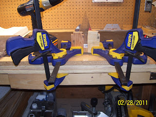
The pic below is a side view. Shows my backer piece of wood in place to keep the metal from bending as the drill bit penetrates the metal.


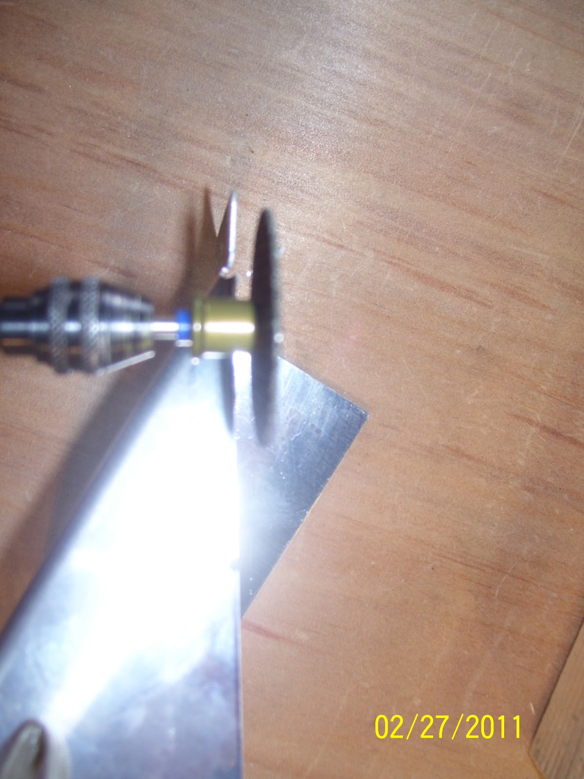
A pic of the notorious unibit. Starts at 1/4 inch and gets larger from there. It is basically a step drill with multiple dimensions. You simply keep pushing the drill forward to make larger holes as shown by the scale on the inside.

Below is a trick I learned on VAF. You mark the location of the drill for the correct sized hole with a sharpie to make it easier to tell when you have drilled the desired hole size.

And here we have the messed up final hole, which is a bit to large since I went too deep anyway, and also because I did not pilot drill this hole to at least 1/4 inch using a normal drill bit first, before using the unibit to finish the hole. First shot shows the hole in the flange of the rib by itself, and how terribly close it is to the edge of the flange. The next shot shows the rib assembled with the other parts, and how the hole is mis-aligned with the other holes in the other parts.


So I got to order another part - Whooopieeeee! A new bottom rib for the rudder is also on its way today. Luckily they had not shipped my other order from yesterday yet, so I was able to add the rib to that order and save some additional shipping charges. Rest assured, when the new rib arrives, I will be using standard drill bits to enlargen the pilot hole before I even think about using the unibit to finish it. The other thing I will do is ensure that the unibit is in an adjustable speed drill that will turn very slowly. Going fast with a unibit is a disaster waiting to happen in my opinion. Hopefully the next several days spent working on the frame of the rudder will go much smoother, once I get the replacement parts.
KPR, and if any of you followers or visitors are also building or thinking about building one of these great airplanes, please learn from these posts, and don't make the same mistakes!
So, I ordered my second part from Vans so that I can do it over. Vans should change this to make it right. I am not too happy about needing to replace a part because their plans and instructions are incorrect. Oh well, it happens sometimes. Just have to do what you ahve to do to fix it.

Now for the second fiasco - this one was all my doing. Instructions from Vans say to enlargen a 1/8 inch hole to 3/8 inches in the forward flange of the bottom rib for the rudder frame using a unibit. This hole is one of several holes in several different parts that all align to provide access for the bottom rod end bearing (hinge) to insert into a plate nut on the very back of the last part in the assembly. Again, a nut plate is similar to a blind nut. It has two attach points on either side for rivets to hold it in place, and the middle is sized and threaded to accept the proper sized screw or bolt. The trick is that this hole, when finished, is already very close to the edge of the flange on the rib if done properly. If you don't get it just right, it will be off center and too close to the edge when you are done. (Exactly what I did!) Pics are worth a thousand words.
First, how many clamps does it take to build an airplane? Answer: ALOT! I rigged up what I thought to be a very cool clamped assembly to ensure that I would get this hole drilled right. Click on the pic to make it larger to see the detail. The hole I am drilling is the one in between the two pieces of wood in the front.

The pic below is a side view. Shows my backer piece of wood in place to keep the metal from bending as the drill bit penetrates the metal.


A pic of the notorious unibit. Starts at 1/4 inch and gets larger from there. It is basically a step drill with multiple dimensions. You simply keep pushing the drill forward to make larger holes as shown by the scale on the inside.

Below is a trick I learned on VAF. You mark the location of the drill for the correct sized hole with a sharpie to make it easier to tell when you have drilled the desired hole size.

And here we have the messed up final hole, which is a bit to large since I went too deep anyway, and also because I did not pilot drill this hole to at least 1/4 inch using a normal drill bit first, before using the unibit to finish the hole. First shot shows the hole in the flange of the rib by itself, and how terribly close it is to the edge of the flange. The next shot shows the rib assembled with the other parts, and how the hole is mis-aligned with the other holes in the other parts.


So I got to order another part - Whooopieeeee! A new bottom rib for the rudder is also on its way today. Luckily they had not shipped my other order from yesterday yet, so I was able to add the rib to that order and save some additional shipping charges. Rest assured, when the new rib arrives, I will be using standard drill bits to enlargen the pilot hole before I even think about using the unibit to finish it. The other thing I will do is ensure that the unibit is in an adjustable speed drill that will turn very slowly. Going fast with a unibit is a disaster waiting to happen in my opinion. Hopefully the next several days spent working on the frame of the rudder will go much smoother, once I get the replacement parts.
KPR, and if any of you followers or visitors are also building or thinking about building one of these great airplanes, please learn from these posts, and don't make the same mistakes!
Subscribe to:
Posts (Atom)