SO I was a little ticked off about this, but that quickly subsided, since I was at least able to start working on some other things. I will call Vans on Monday and see if I can get them to expedite another part that has been quality checked first.
Lots of pics to post this time as well - most of the time I spent since last post was on trying to resolve a problem with the R713 counter balance skin and the R 703 tip rib. The issue was trying to get the two pre-drilled holes in the front flange of the rib to line up with the holes in the counter balance skin. Honestly, after all the difficulty this posed for me, I fail to understand why Vans doesn't just leave this area un-drilled so that you can just drill both holes your self without having to do all this matching up crap.
So I'll start with the refrabrication of the R 710 support bracket. I basically trimmed the previous part down to far so that there was not enough edge distance for about 8 rivets that are driven on the sides of the rib and then into the bracket. You need a minimum of 3/16 of an inch from the edge to drive an AN426AD3 (3/32 rivet) rivet correctly.
Here is the new part with the original cut line drawn per plans from Vans, plus a new cut line with about .15 inches added to it to ensure that there is enough material remaining to satisfy the edge distance requirement. The original part is above the new one, and shows the sharpie marks for the rivets and how close tot he edge they are.

After I got it all trimmed up - the main thing to notice is the guide hole that is in the middle of the flange being trimmed. ON the old part, I had trimmed down to a point where at least half of this hole was removed. On the new part, the guide hole remains mostly in tact. Thanks to Steve Riffe and others for shedding some light on all this.


Now on to the R 703 tip rib and R 713 counterbalance skin. basically what you have here is a typical tip rib, there is additional skin that wraps around the rib flanges. Its purpose is to contain the heavy lead counter weight that is used to balance the weight of the rudder behind the hinge line to help prevent flutter and to make the controls move easier and more predictably. This outer skin is spring-tensioned, simlar to the way that the HS skins were. I am not quite sure why this is the case. Anyway, what that means is that you have to cleco it to one side of the rib, then wrap it around the front of the rib, cleco it to the oither side, and then cleco it to the other side.
Then the fun begins. There are two holes in the counter balance skin that have been pre-drilled at the factory. The instructions say to flute the forward flange of the rib as necessary to align the holes in the skin with the pre-drilled holes in the rib. They were a little off. SO I proceeded to flute the forward flange of the rib with my fluting pliers. I did this in a similar manner to all other ribs I have fluted - in between the drill holes and about half way up the edge of the flange. This basically did nothing to align the holes, and so I used my hand seamer to flatten out the flute that I just applied, and began to ponder what I needed to do to align these holes.
After a review of many builders logs and VAF posts about this aprt of the build, I decided that the problem still required the flute in the front rib flange to force the metal in the right position to draw the holes in alignment with each other. You learn a lot about the beahavior of aluminum when certain forces are applied to it during this process. I saw pictures from builder logs where it appeared that no fluting was required at all, and the holes lined right up, and others that showed clecos sticking straight out from those holes instead of at a circular angle as they should have been. The forward flange of the rib and the counterbalance skin is a curved surface, and so if the holes are in the proper position, any clecos inserted into these holes should confirm that positioning by appearing at an angle to each other.
Then one entry in one person's log caught my attention. he said that he had to "flute the flange heavily to get the holes to line up correctly." I decided to try to flute it one more time. This time I would go much deeper into the flange in between the holes, and I too really had to apply a lot of pressure and create a very deep flute, but it worked. The holes started to line up. Only other problem was that the rib flange on one side was bent away from the surface of the counterbalance skin due to the flute lifting the aluminum away just a bit. I took a pair of small hobby pliers that I have had for years that have smooth jaws, and applied some force to the uneven side of the rib flange to straighten it out. The holes were still in good shape after all this. Word of warning to other builders, this process required me to cleco and un-cleco this assembly no less than about 15-20 times before I finally got everything looking the way that I wanted it to. Very time consuming process, and I know I get to do it all over again on the elevators. I can hardly wait!
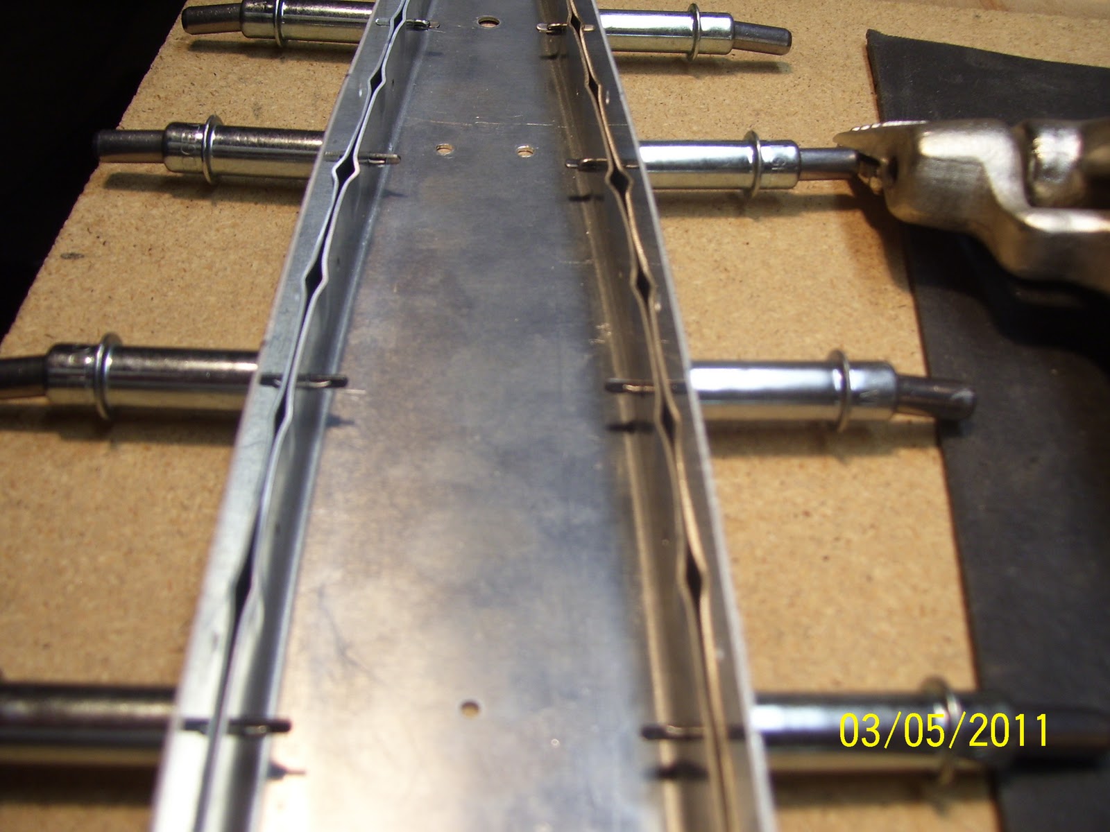
Notice the angle of the two clecoes in the front flange on the left side of this photo. When I started out, these clecoes were either sticking straight out, and were not seated flush against the metal, or they were slightly inversed and angled in the other direction. The holes were not horribly misaligned, but it was obvious when you looked at them after inserting the clecoes that they were.
Also note that I do not have flutes along the flanges on either side near the front of the rib. I see many photos from folks where they have a flute on every single section between holes in the flange. this is usually not necessary, and various segments on the EAA site for Hints for Homebuilders, and posts on VAF, will correctly show that a flute in every single section between holes is usually not necessary. Bottom pic shows the flutes on each side of the rib toward the rear.

The number of tools it took to get this to go together correctly. The fishing line on the lower left of this pic is used for checking the alignment of the rivet holes as you flute the part to straighten it. You take one end of the line and insert it into a rivet hole on one end, and then run it directly down the rib to the very last rivet hole. Then you check to see all the holes are in alignment against the fishing line. If not, you flute the area needed to draw the holes into alignment. Oh yeah, I almost forgot, you also need to sgtraighten the flanges during this process as well so that they are 90 degrees to the web. SO I also used my flnge bending tool, which worked fine on the wider part of the rib, but you have to resort to the hand seamer or a rubber mallet in order to straighten the rear part of this tiny rib. Works rather well. When the holes are aligned and the flanges are 90 degrees perpendicular to the web, you are done fluting and straightening the part. The act of doing all this is not very complicated, just a bit time consuming. In the end it all pays off because the parts all fit together correctly, and final assembly goes together fairly quickly.

And now for the defective rib sent by Vans that I will have to resolve on Monday. Noticed the difference in the height of the flanges on either side. New one is on the right, old one is on the left for comparison.

And another shot of the flanges attempting to show the misaligment of te punched rivet holes on either side. One side is higher than the other by almost 1/16th of an inch. These holes will therefore not align with the holes in the rudder skin properly, so this part is completely unusable. Vans is usually very good about this, but every once in a while they have a problem. I have seen this on various posts on VAF where they had problems because their CAD program was incorrectly configured when setting all of the dimensions for a certain part, to problems with attach holes for the skins to certain spars not lining up correctly. I am hoping that I do not ahve to expend too much effort to ensure that my problem is corrected, but we'll see I guess.


No comments:
Post a Comment