High Ho the Dario a dimpling we will go.....
Just couldn't resist that. As promised, I made what - for me - was substantial progress tonight. I managed to do the following in a couple hours time. All dimpling was performed with the handheld pneumatic squeezer (or heavy SOB as I like to call it), using the -3 dimple dies and the flange yoke:
1. Cleaned the dust off of the rear baffle plate of my Left Wing Fuel Tank Baffle assembly.
2. Removed and dimpled all remaining LE ribs
3. Dimpled the inboard and outboard LE rib holes in the outer skin
4. Dimpled the patch plate and access panel holes in the bottom of the outer skin
5. Verified my temporary installation of Z brackets for the fuel tank were still installed correctly on the wing spar, just as they were back in 2014 when I last touched them.
6. Re-measured the location of the bolt holes in each flange of the Z-Brackets that mounts to the main wing spar web. I reviewed an old post of mine the other day from back in 2014 were I was trying to apply Checkoway's advice to drill the initial bolt holes slightly off center. This was supposed to serve 2 purposes - to allow clearance for the most inboard Z brackets bolt heads so that a wrench or socket could fit around the bolt without interfering with the Z bracket web, and simultaneously allow a little more space for the AN470-4 rivets and Pop rivets to be applied with a rivet set and a pop rivet puller tool, also without interfering as much with the Z bracket web.
These rivets attach the opposite flange of each Z bracket to the back of the fuel tank baffle plate to complete the fuel tank installation. From researching Checkoway's posts further, it looks like you still have to grind away part of a rivet set or pop rivet tool to set those rivets, even if you make the 1/16th of an inch adjustment from center when you measure the location of each hole.
The problem with this approach was trying to figure out how to measure the lengths and widths of each Z bracket flange properly, because of the odd way that these Z-shaped aluminum extrusions were formed. From looking at the bolt holes that I drilled previously, it looks like I was using a flange width of 20/32 of an inch, or 10/16ths, or 5/8ths of an inch, as measured from the flat outer side of each flange. This means that this measurement would include the thickness of about 1/16th of an inch for the web of each Z bracket.
So the middle measurement would then be 10/32nds of an inch, or 5/16ths.
Then a 1/16th of an inch adjustment from that center mark in either direction would be 8/32nds (4/16ths or .25 inches) or 12/32nds (6/16ths or 3/8ths) of an inch, depending on which direction from the web you need to adjust. I am rehashing all of this hear so I can refer back to it as necessary when I get to the point where I need to finish drilling all the remaining holes in each Z bracket.
If I don't include the thickness of the Z bracket web in these measurements, the numbers reduce to a total flange width of 9/16ths of an inch, or 18/32s, and the halfway point would then be 4.5/16ths , or 9/32nds of an inch. Then the 1/16th of an inch adjustment to either side would be 3.5/16ths (7/32nds) or 5.5/16ths (11/32nds). Seriously, trying to figure out precisely where to drill the Z bracket flange holes is a pain in the ass, because these measurements can just drive you crazy.
When you further consider that the width of the hole you must drill for the bolts is 3/16ths of an inch, it does not leave much room to work with if you go either closer to or farther away from the web of the Z bracket. Crazy stuff. When I evaluated this situation, I realized that the "close" measurement would only leave about 1/32 if an inch from the web, and I don't think that a nut plate will fit on the flange with only that much space. So I chose to stick with the measurements that include the thickness of the web.
Then, when you finally look at the numbers, and realize that the only difference that you seem to be working with is just 1/32nd of an inch between the two different measurement methods, you realize that it probably does not make much difference either way, and you will still end up grinding away a large portion of whichever tool you need to use just to make it fit up against the Z bracket web enough to set the rivets.
7. Verified that each of the bolt holes I drilled in the left wing Z brackets appeared to be in the correct place based on the outer measurement technique. I had ordered a set of additional Z brackets after I accidentally drilling a bad hole in one of them in 2014, and I still have those spares today, just in case I need to re-drill any of them.
8. Dimpled the holes along the bottom edge of the Le outer skin. Unfortunately, I found out while doing this that I had missed the match drilling of several holes on both the top and bottom side of the rear of the LE skin where it gets riveted onto each spar flange. What this means is that I cannot countersink all of the corresponding holes in the main wing spar flange, because some of them still have to be match drilled first. Since I know I have to remove the LE one last time before it gets attached to the wing for good, this is fine.
I will match drill the missed holes through the LE skin and the wing spar flanges, and then after the LE comes back off for the last time I will debur and dimple the remaining holes in the skin, and countersink the remaining matching holes in the wing spar flanges. So this is not that big of a deal, but I am bit surprised that I missed so many holes. Sure hope I did better on the right wing.
9. As I expected, when I dimpled the inboard rivet holes with the 426-3 dimple die in the outer LE skin, where the first inboard rib is located, there was one hole that was wallowed out pretty badly - so badly in fact that I am not sure if a -4 rivet will set in this hole correctly, but it is too early to tell just yet. Surprisingly most of the other holes that I was worried about seemed to have made a pretty good dimple. The acid test will come when I get ready to try to drive a rivet in these holes.
10. The holes in the skin for the custom rib that fits next to the first inboard rib have not yet been dimpled, because I will need the dimpling table, C-Frame tool, and my close quarter dimpling tool to dimple those remaining holes in the outer skin. It was getting late, so that is where I stopped for the evening. So I won't know the status of the rivet holes in the tip of the LE skin for of this rib until I get to them tomorrow.
So the next steps are to finish dimpling the remaining rivet holes in the outer LE skin for each of the inboard LE ribs, and then get my micro-stop countersink tool out and run some test countersinks to properly set the depth, and then go to work on the main wing spar flange holes that need countersinking. I envision needing about 2-3 days to complete this work, because there are A LOT of holes to countersink. This will also leave a mess of metal, the likes of which I have not experienced since I drilled all the nut plate holes for the fuel tank.attach points in the main wing spar flanges a long time ago.
Starting to knock things out a little at a time..... Progress! Yeah!
KPR.
Wednesday, September 27, 2017
Research of Checkoway Method for Fuel Tank Frame and LE Mod Remaining Steps
Spent several hours revisiting Dan Checkoway's method for ensuring a proper fit of the fuel tank skin against the LE skin. I also reviewed my own blog from about 3 years ago in 2014 when I was on the path of "normalcy" with this project until I decided to do the LE mod. I had to stop at the point where I normally would have been ready to drill and assemble the fuel tank frame, finish constructing the LE, and moved on to the ailerons and flaps and push rods, like everyone else. Instead, everything stopped at the point where I would have completed the LE.
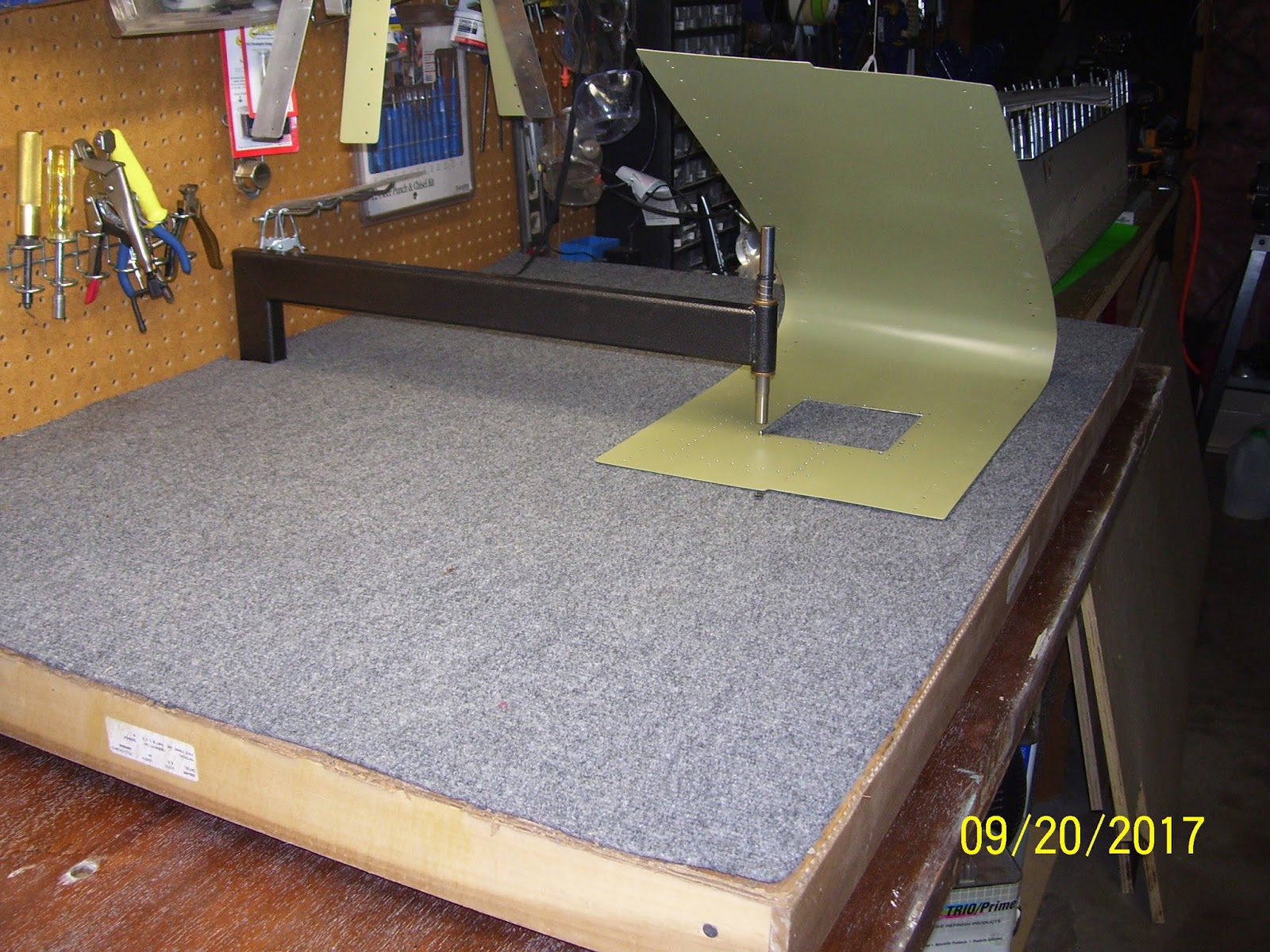
This is next pic is a subtle reminder of that fact.
 Had I decided to do the "normal" thing like everyone else, there would have been no custom-built ribs, no subskin, no patch plate, and instead of the subskin all I would have had to do is install the small square mounting bracket for the access panel. That small square bracket is all I would have had to mount to the outer skin of the LE. There would have been no additional holes to measure and drill, and I am pretty sure that I would have both wings done by now and I would be in the middle of my fuselage. Pretty amazing to think that this small number of customized parts would cause such delays in the building progress.
I am now on what was supposed to be the "hard" part of the modification - figuring out exactly how to measure, cut, and secure the detachable leading edge. I need to figure out the exact placement of all the rivets and nut plates, and then finally take the plunge and make the dreaded cuts of the LE skin.
Before I do that, however, I need to finish dimpling the LE outer skin and remaining ribs, and then I need to countersink a lot of holes in the Main wing spar flanges for the top and bottom mounting holes of the LE skin to the spar. When that is done I can reassemble the LE using the cradle and the table with clecoes, mark the cut lines and rivet and screw holes in the outer skin and subskin, attach it to the main wing spar again, drill the rivet and screw holes for the removable LE, fit the Fuel tank to the wing spar, verify the fit of the tank and the LE skins, drill the inboard Z Bracket rivet holes per the Checkoway procedure, drill the Fuel Tank to LE joiner plate screw and nut plate holes, remove the LE, finish drilling the outboard Fuel tank rib to baffle holes, disassemble the fuel tank skin, finish drilling the remaining fuel tank rib to baffle to Z Bracket holes for the interior fuel tank ribs and Z brackets, disassemble the fuel tank frame, cut the LE outer skin to the predetermined cut lines, fabricate a new removeable LE skin to replace the skin that was cut away from the LE, disassemble the LE ribs and subskin for what should be the very last time, debur and smooth all holes and edges in outer skin and subskin, drill, debur,and dimple all subskin holes and edges, rivet all nut plates in the subskin, drill, debur, and dimple the screw holes in the removeable LE skin in a wrapping and forming procedure to ensure that the removeable skin adheres to the LE shape and dimension with the surrounding outer skin, rivet the LE ribs to the outer skin and subskin, reattach the LE to the wing spar, and finally, rivet the LE to the wing spar (both ribs and skins).
WOW! And I thought I was making "progress!" then, once this is all done, I can 3D all the remaining fuel tank ribs, skins, baffle plate, and fabricate the tank stiffeners. Then I can proceed with the 6 million things you need to do to finish the fuel tanks. Somewhere in between all that I can finally dimple the top wing skins and main wing ribs.
Just a few things left to do until I can finally play with proseal!
Now that I have few more things figured out, progress continues tomorrow.
KPR
This is next pic is a subtle reminder of that fact.

I am now on what was supposed to be the "hard" part of the modification - figuring out exactly how to measure, cut, and secure the detachable leading edge. I need to figure out the exact placement of all the rivets and nut plates, and then finally take the plunge and make the dreaded cuts of the LE skin.
Before I do that, however, I need to finish dimpling the LE outer skin and remaining ribs, and then I need to countersink a lot of holes in the Main wing spar flanges for the top and bottom mounting holes of the LE skin to the spar. When that is done I can reassemble the LE using the cradle and the table with clecoes, mark the cut lines and rivet and screw holes in the outer skin and subskin, attach it to the main wing spar again, drill the rivet and screw holes for the removable LE, fit the Fuel tank to the wing spar, verify the fit of the tank and the LE skins, drill the inboard Z Bracket rivet holes per the Checkoway procedure, drill the Fuel Tank to LE joiner plate screw and nut plate holes, remove the LE, finish drilling the outboard Fuel tank rib to baffle holes, disassemble the fuel tank skin, finish drilling the remaining fuel tank rib to baffle to Z Bracket holes for the interior fuel tank ribs and Z brackets, disassemble the fuel tank frame, cut the LE outer skin to the predetermined cut lines, fabricate a new removeable LE skin to replace the skin that was cut away from the LE, disassemble the LE ribs and subskin for what should be the very last time, debur and smooth all holes and edges in outer skin and subskin, drill, debur,and dimple all subskin holes and edges, rivet all nut plates in the subskin, drill, debur, and dimple the screw holes in the removeable LE skin in a wrapping and forming procedure to ensure that the removeable skin adheres to the LE shape and dimension with the surrounding outer skin, rivet the LE ribs to the outer skin and subskin, reattach the LE to the wing spar, and finally, rivet the LE to the wing spar (both ribs and skins).
WOW! And I thought I was making "progress!" then, once this is all done, I can 3D all the remaining fuel tank ribs, skins, baffle plate, and fabricate the tank stiffeners. Then I can proceed with the 6 million things you need to do to finish the fuel tanks. Somewhere in between all that I can finally dimple the top wing skins and main wing ribs.
Just a few things left to do until I can finally play with proseal!
Now that I have few more things figured out, progress continues tomorrow.
KPR
Sunday, September 24, 2017
More Dimpling and Resetting Bad Rivets in the Subskin
Today I dimpled the holes in the two inboard ribs with the pneumatic squeezer. I also drilled out and re-set about 5 nut plate rivets as I described in the previous post. That was relatively uneventful, and although I did not go through the same agony of clamping blocks like I did before, I did still have to come up with ways to secure the skin to drill out the rivets. When I set the new ones I simply held it in my hand on the workbench, with my fingers close enough to provide good resistance for the rivet set.
I decided to go ahead and dimple all the rivet holes in the subskin and the ribs. I did NOT leave the 2 most forward rivet holes alone as I previously indicated that I might do. I decided that the hole integrity is good for a 3/32 dimple and rivet on both of those parts, so I will see how the outer skin dimple situation goes when the time comes with those wallowed out oversized holes. Email will go to Vans tomorrow to ask if I can increase to an AN426AD-4 rivet if necessary to provide the correct grip for the LE outer skin holes.
Then I scuffed, cleaned and primed the access panel and permanent patch plate with NAPA 7220 self-etching primer.The weather around here is really cold and rainy, and my primer is extremely old as well, so I wasn't sure if it would apply properly or not, with all the high humidity, etc. After letting it dry it seems like it applied OK, so I will go with it for now.
I set one rivet in the wrong hole the other day, and so that one just had to be removed. However, when I checked the dimple one side had been crushed just a bit, so I took the time to clear the bench and set up the C-Frame again to try to reform the dimple a bit. that did not really seem to make much difference, but at least I tried. The hole in question attaches the outer LE skin to the subskin. It would have matched a similar hole in the new access panel's mounting bracket had I used that. Since i am using the subskin for that purpose, that hole won't be riveted until I am ready to secure the entire subskin to the outer skin.
For the rest of the day I studied the Fuel Tank instructions and diagrams to re-acclimate myself to the tank part numbers and assembly sequences. More on that in the posts for next week...
Winter is coming - and I still need heat in my garage....
No pics tonight.
KPR
Saturday, September 23, 2017
Pounded Some Access Panel Nut Plate Rivets
As I mentioned in the previous post, the "act" of setting rivets turns into an artistic, creative adventure that involves trying to figure out how to clamp and secure very odd-shaped parts. I had to dig into my stash supply of wood to come up with an acceptable method for doing so. The pics that follow show how this was done. The basic problem was trying to setup the subskin in such a way that it allowed me handle the rivet squeezer and the part at the same time with both hands. i had to get the subskin at the right height compared to the surrounding wood clamps so that both sides of the squeezer would fit on either side of the subskin without interfering with the wood or the clamps.
The best method I have found for this, mostly since the squeezer is such a damn heavy tool, is to secure the part so that I can use my left hand to steady the yoke and rivet set against the manufactured rivet head so that I know that it is flush with the skin, and hold the squeezer in my right hand. To do this, I have to make sure that the clamping method both secures the skin so that it will not move when I apply the squeezer, and at the same time the clamping solution has to allow enough room for the big-ass squeezer body on the other side of the skin. This is not an easy task when dealing with pre-bent skins, but can be done successfully if you put enough time and thought into how to do this correctly.
For tools I used the pneumatic squeezer with air pressure set to 90 psi, and I used the flange yoke to allow it to fit inside the access panel hole and fit the rivet set as easily as possible. I also used 2 1/2 inch x 1/8 inch flat rivet sets on the top and bottom of the yoke.
This first pic is my initial clamping setup to start setting the bottom row of nut plates. Note the mixture of wood pieces I had to use. I was too lazy to trim the wood to exacting sizes. I just worked with what I had available. This side has enough clearance for the rivet set on the top end of the yoke on the squeezer, so that the rivet set can be centered on the manufactured head of the rivet.
 And the back side, which had to be somewhat lower than the other side to allow room for the squeezer body:
 Notice how I used the end-piece of each clamp on this side, once again to allow as much room for the squeezer body as possible so that it will no interfere with the clamps. I have screwed up more than one rivet in the past because the squeezer ends up hitting either a clamp, the part, or some wood, while in the process of squeezing the rivet. This is why you spend more time setting up the clamping solution than setting the rivets. Some people my even consider this a "simple" operation and probably would have held the part in their hands to set the rivets. Not me. This is always a time consuming, agonizing process for me, but the outcome usually justifies the means for me, since I usually do not have to reset very many rivets after taking the time to set this up correctly.
The next pics show the setup for each nut plate. One cleco on one side and the NAS 1097 3.5 rivet in the other hole:
 And here is a pic of the Squeezer setup. The other thing you have to do is adjust the ram of the squeezer so that it sets the rivet properly so that the shop head is 1.5 x the diameter of the rivet shaft, and has the proper height, etc. the very first rivet is always an experiment, unless you take the time to setup a practice piece with all the same dimensions as the actual part, so you can set it up that way. Otherwise, what I usually do is take a rivet and then activate and hold the squeezer in its compressed state, and place the rivet next to the rivet set to determine if the gap is correct or not. I usually start so that the rivet will not set quite all the way at first. Then I will set the rivet and note the result, and then readjust the ram height accordingly and re-squeeze the rivet one or tow more times until the squeezer is set exactly as it should be for the remaining rivets. In other words, I "creep" up on the proper setting of the ram. Better to be too shallow at first than too close with the ram.
 Next is the hard part of setting the rivet. I don't have enough hands to hold a camera and perform the operation at the same time, so all you get here is the aftermath. One properly set rivet down, several more to go. the trick for this with nut plates is making sure that the rivet set will clear the screw shaft of the nut plate, and still make full, flat contact with the rivet shaft so that the shop head is formed nice and flat against the nut plate flange. This is where the heavy squeezer and sometimes awkward positioning of the squeezer make this feat next to impossible sometimes.

So you position the top of the yoke against the manufactured head, hold that part of the yoke against the skin and apply a little pressure with your left hand, and position the squeezer with your right hand so that the rivet set is perfectly perpendicular with the rivet shaft. Then you hit the trigger and pray that it all comes out good. Centering the rivet set against the manufactured head is always the challenge.
As a footnote, you always have better control during the entire squeezing operation by using a hand squeezer instead of the standard pneumatic one. The only way that this tool would have worked in this situation is by positioning it so that the flat rivet set against the manufactured head would have been on the moving ram, and this is just something I try to avoid at all costs, because it is tricky at best to try to keep the rivet set on the end of a moving ram in place without it moving somewhat. The handles would not fit in between the curved skins, which it what I needed in order to make the hand squeezer work the way that I would want it to.

And after the second rivet is set, you get this blurry pic:
 And the other side
 And here is a rare pic of yours truly performing the positioning exercise previously described/ You'll need to note that I have turned the part around and rearranged the clamps and wood blocks to allow riveting the nut plates along the remaining edges. Like I said - you have to get creative sometimes:


 And here are the results after the job was "done." Truth be told, even after all this prep, I ended up with about 5 rivets that I was not happy with. Three of them I was able to "coax" into position with a punch and hammer to get the manufactured head to sit a bit more flush against the skin than they turned out with the squeezer. It was that perception problem I described earlier where, despite your best efforts, sometimes you just can't tell very easily if the rivet set is flush and flat against the skin, and you end up with a slightly raised rivet head. Flush rivets need to be just that - flush - against the skin. So you either drill them out and reset them or sometimes you can pound them a little to force them further down into the countersunk hole.


I have no choice but to reset the other two rivets because one of them was inserted into the wrong rivet hole, and the other one was a 1097 rivet inserted into that one hole that mentioned in previous posts that I had to countersink for the larger AN426AD3.5 rivet. IOW I put the smaller rivet head in the hole with the larger countersink, so that one has to be drilled out and replaced with the correct rivet.
After all the rivets were set, I wanted to pre-set the #8 screws into each nut plate. I took some Boe lube ad ran the threads of each screw into that to coat them with this lubricant. I did this in lieu of taking a tap and running that through each nut plate. There is a lot of discussion about this on the forums. The problem is that all nut plates are set to be very very tight, and this is by design. Unfortunately, this makes it very hard to turn the screws.

The rule is:
If it is a structural or otherwise crucial attachment that requires a specific torque or must remain tight for structural reasons, you do NOT run a tap through the nut plate. Instead, the preferred method is to use a lubricant like Boe lube on the screw threads, and this does a great job of allowing the screws to be threaded onto the nut plate much easier, without compromising gripping strength.
Otherwise if there are no structural concerns, such as for access panels or floor boards or other compartments, you can run a tap through the nut plate if you wish. Just know that this effectively removes par of the threads in the nut plate and re-forms and loosens the hole just. SO pick your poison and realize the consequences.
All the screws went on as expected, and even with some of my less-than-perfect rivets, the access panel fits nice and flat up against the subskin, so I was happy about that.
Next steps are to drill out and reset those two remaining rivets, and then scuff, clean and prime the patch plate and the access panel.Then I dimple the ribs and the outer skin and figure out what to do about the wallowed out holes in the outer LE skin. I plan to call Vans about that on Monday because I just discovered that I have some AN426AD-4 1/8 inch rivets that I think I can use in those first couple of holes if the outer skin is too messed up for a -3 rivet.
Pounding rivets was challenging but fun. Only about 12,000 more to go.......
KPR
The best method I have found for this, mostly since the squeezer is such a damn heavy tool, is to secure the part so that I can use my left hand to steady the yoke and rivet set against the manufactured rivet head so that I know that it is flush with the skin, and hold the squeezer in my right hand. To do this, I have to make sure that the clamping method both secures the skin so that it will not move when I apply the squeezer, and at the same time the clamping solution has to allow enough room for the big-ass squeezer body on the other side of the skin. This is not an easy task when dealing with pre-bent skins, but can be done successfully if you put enough time and thought into how to do this correctly.
For tools I used the pneumatic squeezer with air pressure set to 90 psi, and I used the flange yoke to allow it to fit inside the access panel hole and fit the rivet set as easily as possible. I also used 2 1/2 inch x 1/8 inch flat rivet sets on the top and bottom of the yoke.
This first pic is my initial clamping setup to start setting the bottom row of nut plates. Note the mixture of wood pieces I had to use. I was too lazy to trim the wood to exacting sizes. I just worked with what I had available. This side has enough clearance for the rivet set on the top end of the yoke on the squeezer, so that the rivet set can be centered on the manufactured head of the rivet.


The next pics show the setup for each nut plate. One cleco on one side and the NAS 1097 3.5 rivet in the other hole:


So you position the top of the yoke against the manufactured head, hold that part of the yoke against the skin and apply a little pressure with your left hand, and position the squeezer with your right hand so that the rivet set is perfectly perpendicular with the rivet shaft. Then you hit the trigger and pray that it all comes out good. Centering the rivet set against the manufactured head is always the challenge.
As a footnote, you always have better control during the entire squeezing operation by using a hand squeezer instead of the standard pneumatic one. The only way that this tool would have worked in this situation is by positioning it so that the flat rivet set against the manufactured head would have been on the moving ram, and this is just something I try to avoid at all costs, because it is tricky at best to try to keep the rivet set on the end of a moving ram in place without it moving somewhat. The handles would not fit in between the curved skins, which it what I needed in order to make the hand squeezer work the way that I would want it to.

And after the second rivet is set, you get this blurry pic:


I have no choice but to reset the other two rivets because one of them was inserted into the wrong rivet hole, and the other one was a 1097 rivet inserted into that one hole that mentioned in previous posts that I had to countersink for the larger AN426AD3.5 rivet. IOW I put the smaller rivet head in the hole with the larger countersink, so that one has to be drilled out and replaced with the correct rivet.
After all the rivets were set, I wanted to pre-set the #8 screws into each nut plate. I took some Boe lube ad ran the threads of each screw into that to coat them with this lubricant. I did this in lieu of taking a tap and running that through each nut plate. There is a lot of discussion about this on the forums. The problem is that all nut plates are set to be very very tight, and this is by design. Unfortunately, this makes it very hard to turn the screws.

The rule is:
If it is a structural or otherwise crucial attachment that requires a specific torque or must remain tight for structural reasons, you do NOT run a tap through the nut plate. Instead, the preferred method is to use a lubricant like Boe lube on the screw threads, and this does a great job of allowing the screws to be threaded onto the nut plate much easier, without compromising gripping strength.
Otherwise if there are no structural concerns, such as for access panels or floor boards or other compartments, you can run a tap through the nut plate if you wish. Just know that this effectively removes par of the threads in the nut plate and re-forms and loosens the hole just. SO pick your poison and realize the consequences.
All the screws went on as expected, and even with some of my less-than-perfect rivets, the access panel fits nice and flat up against the subskin, so I was happy about that.
Next steps are to drill out and reset those two remaining rivets, and then scuff, clean and prime the patch plate and the access panel.Then I dimple the ribs and the outer skin and figure out what to do about the wallowed out holes in the outer LE skin. I plan to call Vans about that on Monday because I just discovered that I have some AN426AD-4 1/8 inch rivets that I think I can use in those first couple of holes if the outer skin is too messed up for a -3 rivet.
Pounding rivets was challenging but fun. Only about 12,000 more to go.......
KPR
Thursday, September 21, 2017
Did the Drilling and Deburring, Now Back to Dimpling....
After a long period of time, the length of which I can't even recall, I finally got to dimple some metal last night and tonight. It started last night by clearing off the work bench to make room for the dimpling table and C-Frame tool. Here is the table with the C-Frame in place and the subskin ready to go. After I countersunk the rivet holes for the nut plates that surround the access panel hole, my next task was to dimple the Screw holes with a # 8 dimple die, which is visible through the first of several holes in the subskin in the next pic after this one:
 In this next pic which is a close up, see if you can find the problem that almost cost me months and months of work:
 Do you see it? Before I divulge the answer, I just have to say that it was such a joy to setup my dimpling table on the "new and improved" work bench, where all the table legs fit on a truly flat workbench, without the need for a hinged extension like the one I had to use so many times before while building the tail section. I was waiting for the day when the decision to go with the solid core door as mt new bench would pay off. It is still a pain in the ass to have to adjust all the adjustable table legs to get the table correctly leveled with the dimple dies, since I do not have "easy" access to the rear of the table, which is up against the wall/pegboard. This makes it a bit difficult to adjust the rear leg height, but I managed to get it done. Another challenge is that with the wing currently on the stand, and the bench being a few inches wider than before, I have less effective space to work with when lifting the table onto the work bench. it wasn't too bad to get it up there, but I still had to be careful not to hit the wing.
Now, back to the pic, do you see it yet? Or rather, I should be asking, do you NOT see it yet? The male dimple die is mounted on the bottom of the C-Frame, and the guide pin from that die is visibly sticking up through the hole. BUT..... To make a dimple, you need to have both a male AND a female die. If you guessed that the female die is not mounted on the ram just above the hole, then you were correct.
In my haste to get to dimpling I had set up everything else correctly, but I forgot the final step of inserting the female die into the ram. And then, yes, for that first hole, I held down the ram over the pin of the male die, and whacked it a few times. After removing the ram I inspected the "dimple" and found it to be very shallow and it did not look right. It also had a very strange looking rim at the bottom of the so-called dimple. It was then that I realized what I had done. (Or not done in this case).
The good news is that, after I inserted the female die into the ram and struck it again, this time the dimple looked like a dimple, although it still has the funny looking edge at the bottom. I test fitted it with the nut plate, and everything fit just fine. So then I finished dimpling all the remaining #8 screw holes.
With the screw holes in the subskin done, the next step was to dimple the access panel cover plate.

And here is the result of the cover plate dimples. Turned out pretty good I think:


And I got the same results for the matching subskin dimples:


I trimmed away a little too much metal in one corner of the opening, so I took a couple of files and radiused that corner just a bit more, and then I trimmed away a little more excess metal on the straight edges. SO what do you do when you finish dimpling two parts that are supposed to fit together - trial fit them of course! This next pic has a #8 screw in one of the holes to see how it will look with the plate secured to the subskin:

Next came the final prep of the rivet holes for each K1100-8 nut plate. After countersinking the holes for the NAS 1097 rivet heads, this exposed some unprimed metal. So I needed to perform the same trick I came up with a long time ago when I countersunk all those fuel tank nut plate holes. I used a tapered Que-Tip (NOT the standard round-headed ones, but specifically tapered and cone-shaped), and some NAPA 7220 self etching primer in a cup, to lightly coat each of the countersunk holes with some primer.
IN this next pic, pay close attention to the white plastic cup in front of the box of Q-Tips:

I shook up the spray can of primer really well, and sprayed some excess primer into the bottom of the cup. I sprayed just enough to allow the Que tip to get enough primer to cover each rivet hole as shown below (pic is a bit blurry - sorry bout that!).

Just insert the primer soaked Q-tip into the rivet hole, remove, and move to the next hole and do it again. After doing a few holes, you figure out how much pressure to apply to deliver the right amount of primer on the edges of each countersunk hole. Excess primer is not much of a problem - you just scrape it away from the edges as necessary. it is also important to test fit the rivets in the hole after you do this. If you get too much primer in there then you can take a deburring bit and run it just enough to either reduce or eliminate the primer, and re-fit the rivet and reapply primer as necessary.
Now for the rest of the story. I almost had another "accident" here that could easily have caused several nasty problems. Luckily, I managed to "escape" relatively unharmed. This next pic shows the bag of the plastic "bath" cups that I used. I guess these are supposed to resemble the old paper Dixie cups, and are designed for holding small amounts of water for rinsing after you brush your teeth, etc.

I primed a few holes, and then paused briefly to check the holes with the applied primer, and I set the cup down on the bench for only a minute or two. Also note that I am doing all this right on top of my carpeted dimpling table. (Not a good idea). When I went to pick up the cup again to saturate the Q-tip one more time, the entire bottom of the cup completely separated from the rest of the cup, and started spilling any remaining liquid primer that was still in the cup.
Most of it ended up dripping on the subskin and my hands and fingers, and luckily there was not very much liquid remaining in the cup. I also thought that some of it splashed onto my work clothes, which I was still wearing for this event, but I seemed to have escaped that disaster as well. But I still had several more holes to prime, so what was I going to use for a container, knowing that using this particular cup was now out of the question?
I had also purchased some different condiment cups a long time ago, as shown in the next pic, that I had also never used before.

Now that I was much more alert as to the potential problems that a plastic container and highly volatile primer might cause when combined together, I knew that I would test this situation out for several minutes by keeping the container on the work bench the entire time, sitting on top of several paper towels - just in case. This time, though, after several minutes, nothing bad happened, and the container seemed to "hold its own" with the primer:

So, several lessons learned (or re-learned) here -
DON'T use the first cups for any type of chemical mixing without testing it first.
DON'T wear your good clothes when priming stuff.
DON'T pick up the cup and hold it near critical tools or parts unless you are certain that retains its viability as a container. (And is not melting away in your hand or smoldering, etc.)
I think that each different cup is made with a different type of plastic, and one is obviously more resistant to the chemicals in the primer than the other.
The next task was to dimple the permanent cover plate with my 3/32 inch dimple dies. So I had to change out the dies in the C-Frame for the smaller holes in the patch plate.

I could have used the pneumatic squeezer for all of the cover plate holes, but I wanted to continue to practice with the C-Frame, since I am going to be using it for quite a while in the near future to dimple the LE, Fuel tank, and main wing skins and ribs. Lots and lots of holes to dimple and countersink. So the more practice I get with the C-Frame the better.
And now the results:


Then it was back to the subskin to dimple all matching holes in that part:


I had been trying to decide if I was going to dimple one final hole that ended up being very close to another hole for the permanent patch plate. This was just the result of a measuring issue where I had already drilled a hole that matched an existing hole in one of the mounting plates that I decided to use as a template for the subskin. Afterward, I decided that I also needed rivet holes about 1/4 inch away from each of the edges. So this resulted in two of those holes being very close together. Anyway, I finally decided to go ahead and dimple it, after seeing that the dimples were far enough apart so that they would not interfere with each other. I did this in the holes for in the patch plate and the subskin.
I will also need to dimple this hole in the outer LE skin. Hopefully it all comes out OK. I think it will.
Tonight I finished (almost) dimpling the remaining 3/32 holes for the subskin for the perimeter holes for what would have been the mounting plate for each access panel, and all but 8 of the most forward LE holes in the subskin, which will need to be dimpled with the close quarter dimpling tool, since the bend in the skin is too stiff to dimple them safely with the C-Frame. I will also need to use the same tool for dimpling the rib flanges that correspond to these same holes.
I also need to scuff, clean, and prime each cover plate. This last pic shows the fit of each plate against the subskin after the dimples were formed. Everything fit together amazingly well. I won't set the rivets on the permanent patch plate to the subskin until I have reassembled the entire LE again, to make sure that the fit between the patch plate and the outer skin is also good.

Everything aligned really, really well after setting all these dimples, and there was not much distortion or bending of the parts either, so I am happy about that.
Another "next" step is to rivet my nut plates for the access panel to the subskin (Yes, another thing I have not done in forever). I spent some time today trying to figure out how to secure the subskin to the bench for this. Anytime I have to do this for some sort of pre-bent skin, you have to get very creative about how you secure and stabilize the part. I'll elaborate more on my thought process for that tomorrow.
One thing you can count on, is that it will involve a lot of clamps and a lot of uniquely shaped and positioned clamping blocks to ensure that I have the security, rigidity, and stability that I need to properly rivet them in place. I also want to make sure that I position the part so that I can apply pressure on the pneumatic squeezer on the non-moving part of the yoke against the manufactured head of the rivet, so that the moving part of the squeezer will be against the rivet stem. Then, once I get all that figured out, I try to position everything so that the squeezer is in my right (dominant) hand, and my left hand is free for holding the part, etc. That bit of wisdom comes from a lot of learning about riveting from actual experience, which you just can't find in any of the text books or the classes. Thankfully I still remember how to apply those experiences.
More tomorrow
KPR

Now, back to the pic, do you see it yet? Or rather, I should be asking, do you NOT see it yet? The male dimple die is mounted on the bottom of the C-Frame, and the guide pin from that die is visibly sticking up through the hole. BUT..... To make a dimple, you need to have both a male AND a female die. If you guessed that the female die is not mounted on the ram just above the hole, then you were correct.
In my haste to get to dimpling I had set up everything else correctly, but I forgot the final step of inserting the female die into the ram. And then, yes, for that first hole, I held down the ram over the pin of the male die, and whacked it a few times. After removing the ram I inspected the "dimple" and found it to be very shallow and it did not look right. It also had a very strange looking rim at the bottom of the so-called dimple. It was then that I realized what I had done. (Or not done in this case).
The good news is that, after I inserted the female die into the ram and struck it again, this time the dimple looked like a dimple, although it still has the funny looking edge at the bottom. I test fitted it with the nut plate, and everything fit just fine. So then I finished dimpling all the remaining #8 screw holes.
With the screw holes in the subskin done, the next step was to dimple the access panel cover plate.


IN this next pic, pay close attention to the white plastic cup in front of the box of Q-Tips:


Now for the rest of the story. I almost had another "accident" here that could easily have caused several nasty problems. Luckily, I managed to "escape" relatively unharmed. This next pic shows the bag of the plastic "bath" cups that I used. I guess these are supposed to resemble the old paper Dixie cups, and are designed for holding small amounts of water for rinsing after you brush your teeth, etc.

Most of it ended up dripping on the subskin and my hands and fingers, and luckily there was not very much liquid remaining in the cup. I also thought that some of it splashed onto my work clothes, which I was still wearing for this event, but I seemed to have escaped that disaster as well. But I still had several more holes to prime, so what was I going to use for a container, knowing that using this particular cup was now out of the question?
I had also purchased some different condiment cups a long time ago, as shown in the next pic, that I had also never used before.

Now that I was much more alert as to the potential problems that a plastic container and highly volatile primer might cause when combined together, I knew that I would test this situation out for several minutes by keeping the container on the work bench the entire time, sitting on top of several paper towels - just in case. This time, though, after several minutes, nothing bad happened, and the container seemed to "hold its own" with the primer:

DON'T use the first cups for any type of chemical mixing without testing it first.
DON'T wear your good clothes when priming stuff.
DON'T pick up the cup and hold it near critical tools or parts unless you are certain that retains its viability as a container. (And is not melting away in your hand or smoldering, etc.)
I think that each different cup is made with a different type of plastic, and one is obviously more resistant to the chemicals in the primer than the other.
The next task was to dimple the permanent cover plate with my 3/32 inch dimple dies. So I had to change out the dies in the C-Frame for the smaller holes in the patch plate.

And now the results:


I will also need to dimple this hole in the outer LE skin. Hopefully it all comes out OK. I think it will.
Tonight I finished (almost) dimpling the remaining 3/32 holes for the subskin for the perimeter holes for what would have been the mounting plate for each access panel, and all but 8 of the most forward LE holes in the subskin, which will need to be dimpled with the close quarter dimpling tool, since the bend in the skin is too stiff to dimple them safely with the C-Frame. I will also need to use the same tool for dimpling the rib flanges that correspond to these same holes.
I also need to scuff, clean, and prime each cover plate. This last pic shows the fit of each plate against the subskin after the dimples were formed. Everything fit together amazingly well. I won't set the rivets on the permanent patch plate to the subskin until I have reassembled the entire LE again, to make sure that the fit between the patch plate and the outer skin is also good.

Another "next" step is to rivet my nut plates for the access panel to the subskin (Yes, another thing I have not done in forever). I spent some time today trying to figure out how to secure the subskin to the bench for this. Anytime I have to do this for some sort of pre-bent skin, you have to get very creative about how you secure and stabilize the part. I'll elaborate more on my thought process for that tomorrow.
One thing you can count on, is that it will involve a lot of clamps and a lot of uniquely shaped and positioned clamping blocks to ensure that I have the security, rigidity, and stability that I need to properly rivet them in place. I also want to make sure that I position the part so that I can apply pressure on the pneumatic squeezer on the non-moving part of the yoke against the manufactured head of the rivet, so that the moving part of the squeezer will be against the rivet stem. Then, once I get all that figured out, I try to position everything so that the squeezer is in my right (dominant) hand, and my left hand is free for holding the part, etc. That bit of wisdom comes from a lot of learning about riveting from actual experience, which you just can't find in any of the text books or the classes. Thankfully I still remember how to apply those experiences.
More tomorrow
KPR
Tuesday, September 19, 2017
Preparing for Deburring Dimpling and Countersinking of the Left Wing Leading Edge
I finally did some more work on the plane yesterday and today. Yesterday I put the LE back in the cradle after drilling all remaining rivet holes for the patch plate, subskin, and outer skin. I disassembled the first two inboard ribs so that I could separate the subskin from the assembly to debur both sides of the new holes. There were also a couple of scratch marks on the rear rib flange of each rib that needed to be scuffed out and re-primed. I re-shot them with some NAPA 7220 self etching primer (rattle can).
I then started reviewing Vans instruction manual - something I had not done in detail for a very, very long time. I had been so busy doing all the "other" things I needed to do for this modification that I am doing that there was no need to get back to the instructions in the manual until the large majority of things pertaining to the mod were completed.
The manual basically has you completing the LE structure, leaving it clecoed to the Wing spar, and then you start to work on the fuel tanks.You are supposed to get to a point where the fuel tank is mounted on the wing with the LE, and then you final drill the screw holes for the joiner plate where the fuel tank and the LE join together. It then seems to have you removing the LE from the wing and final drilling the rivet holes and riveting the nut plates to the joiner plate BEFORE you rivet the entire LE together. Right now I am not too certain how I am going to approach this.
2 years ago I had started assembling the left wing fuel tank after prepping, straightening, and fluting the tank ribs. It has remained in that state ever since. every time I put it on the wing next to the LE the parts marry up pretty nicely to each other, but the manual has you attaching the Fuel tank to the wing spar first, which means that the fuel tank mounting screw holes have been drilled and dimpled for the #8 screws that attach it to the wing spar. Basically this means that the fuel tank is completed first, and THEN you finish the LE.
I also recall that the instructions to mount and drill all the holes for the fuel tank have been deemed by most builders to be worthless, and much better methods have since been devised. I was following a web site that had this method all documented adn photographed, and now I need to find that site again.
After the deburring was done, I decided to countersink the rivet holes that attach the nut plates to the subskin for the new access panel. I decided to countersink the nut plate holes for NAS 1097 (oops) rivets, since they have a smaller flush head. but still accomplish the same job. Many builders do this for non-structural parts such as access panels or floor panels. The following pics show how I set up for this and tools I used.
 I used my standard single-cutter deburring bit and my craftsman cordless screw driver to countersink the rivet holes. This next close up shows t he countersunk rivet holes and difference between the head sizes of the 1097 AN 3-4 rivet and the AN426AN3-4 rivet:
 I used the deburring bit in the screw driver with the part clamped over the top of two pieces of wood with a gap in the middle so that could trial fit the rivet and remove it as needed until the countersink was set to the proper size for the rivet head to sit flush with the surface of the subskin.

Having not done this sort of work for a long time, I only over-did one of the rivet holes, so I had to keep going to size it for the regular AN426 AN3-4 rivet and I think that worked out fine.
This last pic is of the clamped part on the workbench. I am trying to make sure that I stick some very hard-learned lessons that securing the part properly is the most important thing to do when prepping a part for drilling, shaping, or riveting:
 Next steps are to get out the C-frame and prepare to dimple the #8 screw holes. As memory serves, I believe it is always better to use the C-frame to dimple the larger holes, and very important to make sure they are properly deburred and have clean edges, to prevent cracks from forming in these areas.SO this means I will have to get out my C-frame table - also something that I have not done in very very long time, and setup my C-frame for these holes and the other holes from the outer skin. I used my edge deburring tool to smooth out the larger holes for the screws.
I also got out my pneumatic squeezer, my dimple dies, including my close quarter dimple dies, and my microstop countersink and corresponding bits, and started to plan out the dimpling and countersinking process for the LE.
All for now
KPR
I then started reviewing Vans instruction manual - something I had not done in detail for a very, very long time. I had been so busy doing all the "other" things I needed to do for this modification that I am doing that there was no need to get back to the instructions in the manual until the large majority of things pertaining to the mod were completed.
The manual basically has you completing the LE structure, leaving it clecoed to the Wing spar, and then you start to work on the fuel tanks.You are supposed to get to a point where the fuel tank is mounted on the wing with the LE, and then you final drill the screw holes for the joiner plate where the fuel tank and the LE join together. It then seems to have you removing the LE from the wing and final drilling the rivet holes and riveting the nut plates to the joiner plate BEFORE you rivet the entire LE together. Right now I am not too certain how I am going to approach this.
2 years ago I had started assembling the left wing fuel tank after prepping, straightening, and fluting the tank ribs. It has remained in that state ever since. every time I put it on the wing next to the LE the parts marry up pretty nicely to each other, but the manual has you attaching the Fuel tank to the wing spar first, which means that the fuel tank mounting screw holes have been drilled and dimpled for the #8 screws that attach it to the wing spar. Basically this means that the fuel tank is completed first, and THEN you finish the LE.
I also recall that the instructions to mount and drill all the holes for the fuel tank have been deemed by most builders to be worthless, and much better methods have since been devised. I was following a web site that had this method all documented adn photographed, and now I need to find that site again.
After the deburring was done, I decided to countersink the rivet holes that attach the nut plates to the subskin for the new access panel. I decided to countersink the nut plate holes for NAS 1097 (oops) rivets, since they have a smaller flush head. but still accomplish the same job. Many builders do this for non-structural parts such as access panels or floor panels. The following pics show how I set up for this and tools I used.


Having not done this sort of work for a long time, I only over-did one of the rivet holes, so I had to keep going to size it for the regular AN426 AN3-4 rivet and I think that worked out fine.
This last pic is of the clamped part on the workbench. I am trying to make sure that I stick some very hard-learned lessons that securing the part properly is the most important thing to do when prepping a part for drilling, shaping, or riveting:

I also got out my pneumatic squeezer, my dimple dies, including my close quarter dimple dies, and my microstop countersink and corresponding bits, and started to plan out the dimpling and countersinking process for the LE.
All for now
KPR
Sunday, September 17, 2017
Finished Marking and Drilling Holes for the Patch Plate
Had to embark on the annual Dove hunting trip over the holiday, and this was really the first chance I ahve had to get back to the build since then. IN the previous post I mentioned that I was told to space out the perimeter holes in the patch plate so that they are no wider than the width of the holes of each #8 nut plate that would have been placed on the mounting bracket had I decided to stay with the original access hole and cover plate. WHile measuring out each side of the patch plate I realized that the holes would need to be placed a little closer together to evenly space them between the holes in each outer edge of the plate. The rule was to ensure that the gap between the holes not wider than 11/16ths of an inch, but they could be placed with a smaller gap between holes if necessary.
TO figure out the optimal spacing for the rivets on each side of the patch plate I used a rivet fan tool and tried to space each of the holes out as close to 11/16ths as possible. In reality most of the holes ended up being about 10/16ths apart from each other to allow for the 1/4 inch spacing of the end rivets along each side of the plate.
After marking each hole with a Sharpee I used the hole punch to mark each hole location, clamped the plate to my drill board, and drilled all the holes with a #40 drill bit. Some of the hole locations were not spaced with the exact same gap. This was done to allow the symmetry of the rivet pattern to remain constant in a couple of places, i.e. the rivets along one particular line would be consistent with each other. This only occurred in a couple of places, so I think that the rivet line will still look like they are all evenly spaced.
After drilling each new hole in the patch plate, I deburred both sides of the hole, and then clecoed it back onto the subskin so that I could match drill the holes to the subskin. After that, I removed the patch plate from the subskin adn used my edge forming tool from Cleaveland Tools to put a slight bend along the edges of the patch plate. I did this as a result of some advice from my friend Mike Rettig, who had been through a similar exercise while building his RV-10 wings. He told me that if you don't bend the edges then they do have a tendency to curl upward a bit when the dimples and then the rivets are set. The slight bend in each edge of the plate keeps the edges of bending upward too much. Had he not told me this I would have never done it, and would have experienced the problem for certain. So thanks for the advice Mike.I just need to remember to apply the same thing to the edges of the outer skin that surrounds the subskin to make sure that those edges stay flush as well.
This first pic is of the patch plate and new access panel all clecoed into place on the LE, and the new holes match drilled into the subskin:

This next pic shows the slight bend in each of the edges of the patch plate after using the edge forming tool
 Next is the holes in the patch plate after removing it from the LE. This shows the spacing I used around the perimeter of the plate. Edge distance is 1/4 of an inch around the entire perimeter. Every single one of these holes will need to be dimpled, as will the holes in the subskin.
 Notice the two holes in the left upper corner of the inboard side of the plate. Those two holes ended up really close together because I had already drilled one of the holes which was part of the designed mounting bracket for the NEW access panel. I may abandon this hole and have it filled or I may dimple both of them and rivet them. It will depend on the size of the dimple and if each dimpled hole will not interfere with the hole next to it. This is the only area of the new patch plate that I am uncomfortable with. I am totally satisfied with the rest of the hole patterns and placement. As stated previously, no additional rivets should be needed other than around the perimeter of the plate, since no specific compression of expansion forces are expected to be applied to this specific area of the skin, other than the same forces that will be applied to this entire section of the Le skin in between the attach points of the skin to each rib. IN effect, this area is simply being stiffened a bit to compensate for the loss of strength that may have occurred when I cut out the additional outer skin material for the mew access plate location.
Last is the pic of the subskin after the holes were match drilled and the patch plate was removed. I am mainly checking for rivet hole alignment here. not exactly perfect in a couple of spots, but close enough for me:
 Next steps:
Removal of the LE and disassembly again for deburring various outer skin and subskin holes. (hopefully for the final time, but I doubt it).
Assessment of the wallowed out holes and final decision if I am going to need to use AN470 rivets to secure the outer skin to the rib and the subskin.
Dimpling all LE holes that will require dimples in all parts.
Countersinking all remaining LE skin attach holes to the Main wing spar flanges.
Make final decisions about the location of the cuts for the LE removal and rivet layout, as well as nut plate location determination for the removable LE section.
TO figure out the optimal spacing for the rivets on each side of the patch plate I used a rivet fan tool and tried to space each of the holes out as close to 11/16ths as possible. In reality most of the holes ended up being about 10/16ths apart from each other to allow for the 1/4 inch spacing of the end rivets along each side of the plate.
After marking each hole with a Sharpee I used the hole punch to mark each hole location, clamped the plate to my drill board, and drilled all the holes with a #40 drill bit. Some of the hole locations were not spaced with the exact same gap. This was done to allow the symmetry of the rivet pattern to remain constant in a couple of places, i.e. the rivets along one particular line would be consistent with each other. This only occurred in a couple of places, so I think that the rivet line will still look like they are all evenly spaced.
After drilling each new hole in the patch plate, I deburred both sides of the hole, and then clecoed it back onto the subskin so that I could match drill the holes to the subskin. After that, I removed the patch plate from the subskin adn used my edge forming tool from Cleaveland Tools to put a slight bend along the edges of the patch plate. I did this as a result of some advice from my friend Mike Rettig, who had been through a similar exercise while building his RV-10 wings. He told me that if you don't bend the edges then they do have a tendency to curl upward a bit when the dimples and then the rivets are set. The slight bend in each edge of the plate keeps the edges of bending upward too much. Had he not told me this I would have never done it, and would have experienced the problem for certain. So thanks for the advice Mike.I just need to remember to apply the same thing to the edges of the outer skin that surrounds the subskin to make sure that those edges stay flush as well.
This first pic is of the patch plate and new access panel all clecoed into place on the LE, and the new holes match drilled into the subskin:

This next pic shows the slight bend in each of the edges of the patch plate after using the edge forming tool


Last is the pic of the subskin after the holes were match drilled and the patch plate was removed. I am mainly checking for rivet hole alignment here. not exactly perfect in a couple of spots, but close enough for me:

Removal of the LE and disassembly again for deburring various outer skin and subskin holes. (hopefully for the final time, but I doubt it).
Assessment of the wallowed out holes and final decision if I am going to need to use AN470 rivets to secure the outer skin to the rib and the subskin.
Dimpling all LE holes that will require dimples in all parts.
Countersinking all remaining LE skin attach holes to the Main wing spar flanges.
Make final decisions about the location of the cuts for the LE removal and rivet layout, as well as nut plate location determination for the removable LE section.
Subscribe to:
Posts (Atom)