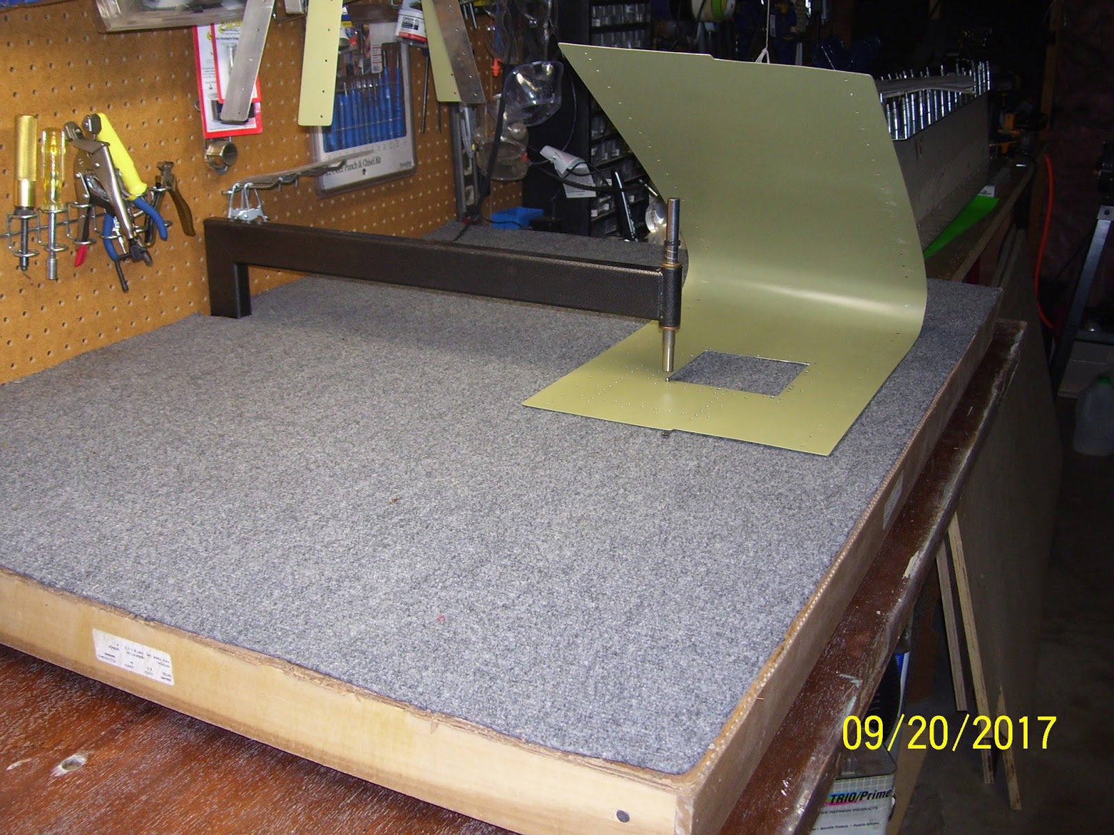

Now, back to the pic, do you see it yet? Or rather, I should be asking, do you NOT see it yet? The male dimple die is mounted on the bottom of the C-Frame, and the guide pin from that die is visibly sticking up through the hole. BUT..... To make a dimple, you need to have both a male AND a female die. If you guessed that the female die is not mounted on the ram just above the hole, then you were correct.
In my haste to get to dimpling I had set up everything else correctly, but I forgot the final step of inserting the female die into the ram. And then, yes, for that first hole, I held down the ram over the pin of the male die, and whacked it a few times. After removing the ram I inspected the "dimple" and found it to be very shallow and it did not look right. It also had a very strange looking rim at the bottom of the so-called dimple. It was then that I realized what I had done. (Or not done in this case).
The good news is that, after I inserted the female die into the ram and struck it again, this time the dimple looked like a dimple, although it still has the funny looking edge at the bottom. I test fitted it with the nut plate, and everything fit just fine. So then I finished dimpling all the remaining #8 screw holes.
With the screw holes in the subskin done, the next step was to dimple the access panel cover plate.


IN this next pic, pay close attention to the white plastic cup in front of the box of Q-Tips:


Now for the rest of the story. I almost had another "accident" here that could easily have caused several nasty problems. Luckily, I managed to "escape" relatively unharmed. This next pic shows the bag of the plastic "bath" cups that I used. I guess these are supposed to resemble the old paper Dixie cups, and are designed for holding small amounts of water for rinsing after you brush your teeth, etc.

Most of it ended up dripping on the subskin and my hands and fingers, and luckily there was not very much liquid remaining in the cup. I also thought that some of it splashed onto my work clothes, which I was still wearing for this event, but I seemed to have escaped that disaster as well. But I still had several more holes to prime, so what was I going to use for a container, knowing that using this particular cup was now out of the question?
I had also purchased some different condiment cups a long time ago, as shown in the next pic, that I had also never used before.

Now that I was much more alert as to the potential problems that a plastic container and highly volatile primer might cause when combined together, I knew that I would test this situation out for several minutes by keeping the container on the work bench the entire time, sitting on top of several paper towels - just in case. This time, though, after several minutes, nothing bad happened, and the container seemed to "hold its own" with the primer:

DON'T use the first cups for any type of chemical mixing without testing it first.
DON'T wear your good clothes when priming stuff.
DON'T pick up the cup and hold it near critical tools or parts unless you are certain that retains its viability as a container. (And is not melting away in your hand or smoldering, etc.)
I think that each different cup is made with a different type of plastic, and one is obviously more resistant to the chemicals in the primer than the other.
The next task was to dimple the permanent cover plate with my 3/32 inch dimple dies. So I had to change out the dies in the C-Frame for the smaller holes in the patch plate.

And now the results:


I will also need to dimple this hole in the outer LE skin. Hopefully it all comes out OK. I think it will.
Tonight I finished (almost) dimpling the remaining 3/32 holes for the subskin for the perimeter holes for what would have been the mounting plate for each access panel, and all but 8 of the most forward LE holes in the subskin, which will need to be dimpled with the close quarter dimpling tool, since the bend in the skin is too stiff to dimple them safely with the C-Frame. I will also need to use the same tool for dimpling the rib flanges that correspond to these same holes.
I also need to scuff, clean, and prime each cover plate. This last pic shows the fit of each plate against the subskin after the dimples were formed. Everything fit together amazingly well. I won't set the rivets on the permanent patch plate to the subskin until I have reassembled the entire LE again, to make sure that the fit between the patch plate and the outer skin is also good.

Another "next" step is to rivet my nut plates for the access panel to the subskin (Yes, another thing I have not done in forever). I spent some time today trying to figure out how to secure the subskin to the bench for this. Anytime I have to do this for some sort of pre-bent skin, you have to get very creative about how you secure and stabilize the part. I'll elaborate more on my thought process for that tomorrow.
One thing you can count on, is that it will involve a lot of clamps and a lot of uniquely shaped and positioned clamping blocks to ensure that I have the security, rigidity, and stability that I need to properly rivet them in place. I also want to make sure that I position the part so that I can apply pressure on the pneumatic squeezer on the non-moving part of the yoke against the manufactured head of the rivet, so that the moving part of the squeezer will be against the rivet stem. Then, once I get all that figured out, I try to position everything so that the squeezer is in my right (dominant) hand, and my left hand is free for holding the part, etc. That bit of wisdom comes from a lot of learning about riveting from actual experience, which you just can't find in any of the text books or the classes. Thankfully I still remember how to apply those experiences.
More tomorrow
KPR
No comments:
Post a Comment