SO my last post was a week ago this past Saturday. On Sunday the 22nd I had another long day of airplane work done. Only problem was, by dinner time on that Sunday I was starting to feel like death warmed over. I very cold breeze was flowing right through me. I managed to make it to work on Monday but then everything really came crashing down. I went to bed immediately after getting home Monday evening, and went dtraight to bed, wearing all my work clothes AND my heavy winter coat under the covers just to stay warm, shivering like crazy with fever. Long story short, spent the rest of the week and home, was diagnosed with a really bad case of strep, got the antibiotics from the doc, and have been fighting to recover ever since. I am almost there, but it likes to hang on during these final stages and only give me small amounts of recovery each day, just to keep me in check I guess. Tonight was really the first time I have gotten back to airplane building since I fell ill.
Needless to say not much airplane work done, but got some things done:since my last post:
1. Researched and ordered a set of key hole wire strippers from Sears after finding out that the folks at the Ray Allen company are using them for their shop work on all the tiny 26 gauge tefzel wires they use to manufacture their trim servos. Unfortunately Sears would not sale the one stripper I needed by itself. It only came as a set with 3 other stripper tools. But at $45.00, compared to the $220.00 the Ideal automatic wire stripper was going to cost me, I decided it was worth the investment. The part number of the stripper is 73574, and is supposed to strip 22 to 32 AWG stranded wire. After practicing a bit, it still slices clean through about 4 of the 19 strands of wire in each conductor, but perhaps with some more practice I can prevent this from happening.
2. Finished priming adn installing the servo mounting brackets onto the cover plate for the trim tab servo. Used AN 1097 "Oops" rivets for the two rivets on the lowest side of the mounting brackets so that I would not have to dimple the cover plate and the mounting bracket holes which would have interfered with the bottom of the trim servo cover. This is a well known problem and the solution works great. Get the Oops rivet set from Avery Tools.
3. Cut my push rod for the trim servo according to my specs - about 3 and 5/8 inches. I think this will work out just about right. I cut the rod with the dremel cutoff wheel, then deburred the ends on the grinder so that the two stop nuts can be screwed onto the threaded rod. These will snug up under the base of each clevis to prevent the rod from turning, although this is such a snug assembly that I don't think here is much chance of that ever happening.
4. I have all but completed the trim tab, however I had two MK319-BS pop rivets on the bottom of the outboard edge that did not sit down in the dimples very well, and so I tried to drill one of them out tonight. I don't know what is going on, but I cannot drill this SOB'n thing out!. My drill bits just spin and do not remove any material. Now I need to find out what is going on and how to rememdy this little problem. Should have just left them alone.
5. I trimmed up the outboard edge of the elevator that sits next to the outboard edge of the trim tab. Vans wants a minimum of 3/32 inches clearance to prevent any possibility of binding, which is very wise. The problem is that there is about 1/32 inch of play in between each of the eyelets in the hinge, so you have to decide if you want 3/32 inches with the pay or without the play, and file the edges down accordingly. I decided to trim it without allowing for the play, so that means that with the play there is only about 1/16 inches of clearance. I will see what the tech counselors say when they come to visit. The problem is, until you get the trim tab and the trim servo installed for the last time, you can't know exactly how the hinge will position itself through the entire range of motion. Also, until you perform final trimming of the edges of the elevator, you cannot finish installing the last riblet. Everything depends on everything else. Makes you wonder how you ever move forward on this project sometimes.
Anyway, the edges are nice and straight. I must have messed up my initial measurements whne trying to determine where to cut the tabs off of the elevator a long time ago, because the gap on the bottom side was already pretty much where it needed to be, but I still needed to remove about another 3/32 of material from the top skin edge to get the proper clearance on that side. Careful use of the dremel tool and a file took care of that in almost no time at all.
6. The last thing I did tonight was to mark the hole locations on the elevator riblet and transfer them onto the elevator as best I could. Again, if I had it to do over again I would probably form my own riblets so that the flanges would have no predrilled holes in them at all, and then it would be a snap to drill the holes through both the skin AND the riblet, instead of trying to reverse-match drill the damn things so that the existing holes in each riblet can be used.
I bought a 25 watt soldering iron for the electrical wiring work, and also a small slender heat gun designed specifically for working with electronics wiring projects and heat shrink tubing in tight places. I think I can even fabricate a metal spout to attach to the existing one to ahve total control over the area to which the heat is applied, so that I do not risk damaging the plastic or other components of the switches or other things I will be installing.
Oh yeah also went to see the movie Red Tails with the RV Denver clan a week ago. That was fun and it was good to see most everybody again.
Anyway, no pics tonight cuz I am still in recovery, and I am too tried to upload all of them. Will try to do that tomorrow. PLan is to get the final riblet drilled, deburred, and riveted tomorrow, and then hopefully I can start working on rolling some leading edges.
Tuesday, January 31, 2012
Saturday, January 21, 2012
434 hours-Trim tab servo mounting bracket and cover plate - take 2
So I received the new cover plate from Van's and followed the same procedures in the previous posts to sraw a new center line on the cover plate that basically centers the output shaft of the servo arm with the center of the access hole in the plate and the elevator. In short, the line was moved barely an eighth of an inch or so from where it was.
Here I have attached the cover plate to the elevator and placed my straight edge/ruler over the slots where the center point is. I just roughly estimated where center was, and made a mark on both sides and drew the line.


Next I centered up the trim tab on the elevator and took my straight edge and extended it from the new line on the cover plate down to the control horn. Now you can see that the horn is displaced off to one side of the horn, just as I had expected.

Next is transferring the line from the top of the cover plate to the bottom. I also deburred and dimpled the cover plate, including the edges:


And here we are all clecoed together and clamped to the drawing for final positioning and drilling the mounting bracket holes to the cover plate.
 Oh yeah, I did also draw another outline of the cover plate on my cardboard template. Here you can see the difference in the original line that I drew and the new one which is now centered with the slot on the plate. I did not notice the reflection on the bottom of this pic until just now. I was holding the card board against the top of the elevator skin. Amazing - even after all the finger prints and dings and scratches on the skin, it still acts like a mirror! So, just focus on the upper two thirds of the photo. Sorry for the illusion...
 These next two shots attempt to show the clearance of the clevis and control arm of the servo against the cover plate when the arm is fully extended.

 What this confirms is that even when the arm is fully extended there is still adequate clearance of the clevis pin and clevis with the cover plate. The only other concern at this point will be the clearance of the cotter pin that is inserted into the clevis pin to keep everything attached and secure.
Here are the mounting brackets after removing the cardboard template, reclamped back onto the drill board. I once again traced the outline of the mounting brackets to ensure that they remain correctly aligned when I drill the rivet holes to #40 through the cover plate.

And here are the first 4 holes drilled and clecoed directly to the drill board. The last two holes extend beyond the drill board and I simply went ahead and drilled those as well in the overhanging position.

And finally checking the alignment of the threaded rod from the servo out to the control horn of the trim tab. Slightly off to one side, just as I had expected. What I have not shown is that I used Gorilla duct tape strips to hold the trim servo to the mounting brackets and keep the servo wires from getting crimped while I installed the servo in the elevator. There are screws and lock nuts to attach the trim servo to the mounting brackets, but those lock nuts are stiff as hell, and I did not want to permanently afix the servo to the mounting brackets just yet, so I used the tape.
The access hole, although appearing to be quite spacious when viewed by itself, is actually only just large enough to insert the cover plate-trim servo assembly into the elevator. You have to find the special method to twist and turn it just right so that it will fit into the hole. You also have to remember to position the servo arm so that it allows enough clearance to insert or remove the assembly. I found that centered works out pretty well. This is a note I will have to make in my maintenance procedures when I perform each annual condition inspection, or any time I need to service that part of the plane.
I don't know if others end up grinding down their nut plate flanges to align with the edges of the elevator skin around the access hole, but after fiddling with trying to get the servo inserted into the elevator, I don't see how you can get the mounted servo in there without doing exactly that. That is how closely matched the hole dimensions are to the cover plate assembly.
 Pretty much centered through the hole, but what about the offset of the control horn? Now back to the great debate - bend the rod or don't bend the rod. So I called the Ray Allen company and spoke to one of Ray's sons that now runs the company. Had a very nice conversation with him and learned that this company has it's roots from associations with Jim Kraft, maker of the Kraft radio control systems that were widely used in the 60s and 70s, right about the same time I was becoming interested in the hobby. In fact, my neighbor Kevin and his wife Mary stopped by while I was in the garage the other night to check on my progress. When Kevin saw the servo (he is also an RC enthusiast) his first comment was " gee, that looks just like a big RC servo." He is absolutely correct, but it is a heavy duty servo compared to the smaller ones that are designed for use in RC airplanes, but they all are basically designed to do the same thing.
Anyway. The main reason for the call was to detemine what to do with the Rod. I was told that he had looked at many many RV6s and other airplanes that had been out in the field for quite some time now, and he had never seens signs of the hole in the control horn warbeling or being worn away due to stresses of non alignment of the rod with the horn. Based on that, he said they don't recommend putting any bends in the rod, and his advise was just to mount everything up and check it, and then monitor it after the flying begins. I told him that I also noticed that the two part horn assembly tends to separate at the tip just a bit where the holes for the clevis pin are located, but when I apply force to the rod to move the trim tab it actually brings the horns closer together, which is good.
So maybe it will be fine "as is" with no bending of the rod. If you look closely at the plans from Vans, they also show the trim servo assembly with the one side of the wide clevis butted up tight to one side of the trim tab control horn. This leaves a very large gap of the other side of the clevis. I was always taught to aim for the mid point of anything that has any play to one side or the other, for reasons similar to learning how to land a plane on the center line of the runway. You keep it on the center line so that if anything should happen such as a blown tire, locked up brake, or gust of wind, or anything that might induce a side load to the object, you still have some margin of runway on either side of the center line to keep from running off the runway surface. Or in this case, from running into either edge of the control horn, which would create wear over time. Oh well - that's the way that Van's shows it in the plans, and with over 7500 of them flying out there, I guess I will follow suit.
In fact, he even asked me if the horn was still designed such that it is just two pieces of thin .020 aluminum connected together. I told him yes it was. He asked me because the width of the opening in the clevis that slides over both sides of the hole in the control horn is at least 3/8 inches wide, much wider than the thickness of the two control horn pieces. I was even wondering if we needed to insert a bearing of some sort to remove the gap, but I guess not.
Then we talked about the new trim tab assembly on the new Cessna Skycatcher, which is also apparently using one of their (Ray Allen) control assemblies. He commented about how beefy, ugly, and overbuilt that trim tab was. So I think it's kind of funny, on the one hand you have an overbuilt assembly for a production aircraft, and then on the other hand you have the "just good enough" approach that Van's is using. As long as there is no binding during movement of the tab, then it should be fine.
Here is a final pic of the rod as it exits the slot. Note the original mark on the top where the old rod centerline was located, compared to the centered location now. Whew, now that that is over, on to the next thing, which is to cut the rod to te proper length. SO this gave rise to another question to Ray Allen. How far do you screw in the rod to each clevis? He told me that the MINIMUM is only 3 turns on to each clevis. Apparently they have conducted tests where he told me that it took 400 pounds of pressure to separate the clevis from the rod with it attached by only three turns on each end. WOW! The trim servo itself is only designed to handle about 40 pounds of force. This means that inserting more thread into the clevis is a plus for strength.
 In my RC days there was a standard practice to take the 1/16 inch threaded rods we use in the hobby and screw them all the way into the shaft of the nylon clevis, and add another 1/16 inch of threads as a safety factor and to allow for adjustments. This typically ended up being about 3/4 of an inch of thread inserted into the clevis. I can only manage to screw in the rod for this assembly about the same amount - about 3/4 inches, which is still way below the hole on the other end of the clevis. Apparently this is more than adequate enough. This also seems to be about the length shown in the plans from Vans, if you adjust for the scale of the drawing, which brings up another thing.
I searched long and hard on VAF to find posts that deal with the correct length to cut the rod, which is not mentioned anywhere in the plans. All you get is the drawing at 3/8 scale with no notes about this at all. This turns out to be a common practice with most of Vans full sized plans. Many drawings of subassemblies are set to 3/8 scale. I have found that there are many times that I want to determine the actual measurements from the scale drawings, and so in order to do this you have to know how to convert from smaller scale to actual size, and sometimes you need to go in reverse from actual size down to 3/8 or some other scale.
Anyway, after hours of searching I could not find anything that gave me the answers I was looking for. Some people made a reference to 3 3/8 inches, saying that this is what Vans recommends. But as I said, I could not find reference to that measurement anywhere in the plans. Finally I found one post with only two entries from 2007, and they basically said that they just estimated the length and cut it. Perhaps the plans were different back then, I don't know, but being an avid RC scale enthusiast for a long time, I was just not satisfied with the "esitmate and cut" approach to this. So I reopened this thread with a post that describes the detailed process to perform the mathematical conversion from the 3/8 scale drawing in the plans to reveal the approximate actual length of rod that should be cut. You can see my solution here.
'Nuff for now. Gonna go out with the rest of the Denver RV List crew to have dinner and see the new Red Tails movie tonight. Should be loads of fun. In the mean time, I have a 3 5/8 inch long piece of rod to cut, which is the length that I determined needs to be cut per the steps in the post. This leaves about 3/4 inches of rod in each clevis, and allows for the correct length between the servo arm and the control horn of the trim tab. Initial dry measurements of this length appear to be correct for my installation. Proof enough for me that the scale conversion method works, and takes the guess work out of the process.
Here I have attached the cover plate to the elevator and placed my straight edge/ruler over the slots where the center point is. I just roughly estimated where center was, and made a mark on both sides and drew the line.


Next I centered up the trim tab on the elevator and took my straight edge and extended it from the new line on the cover plate down to the control horn. Now you can see that the horn is displaced off to one side of the horn, just as I had expected.

Next is transferring the line from the top of the cover plate to the bottom. I also deburred and dimpled the cover plate, including the edges:

Not sure why this pic still appears to show that the arm is still a bit off center from the slot in the plate. It really was not. Anyway this gives you an idea of the clearance of the clevis pin to each side of the plate. In actuality it will be a bit different because there are two washers that are placed on both sides of the clevis pin during final assembly.

And here we are all clecoed together and clamped to the drawing for final positioning and drilling the mounting bracket holes to the cover plate.


Here are the mounting brackets after removing the cardboard template, reclamped back onto the drill board. I once again traced the outline of the mounting brackets to ensure that they remain correctly aligned when I drill the rivet holes to #40 through the cover plate.

And here are the first 4 holes drilled and clecoed directly to the drill board. The last two holes extend beyond the drill board and I simply went ahead and drilled those as well in the overhanging position.

And finally checking the alignment of the threaded rod from the servo out to the control horn of the trim tab. Slightly off to one side, just as I had expected. What I have not shown is that I used Gorilla duct tape strips to hold the trim servo to the mounting brackets and keep the servo wires from getting crimped while I installed the servo in the elevator. There are screws and lock nuts to attach the trim servo to the mounting brackets, but those lock nuts are stiff as hell, and I did not want to permanently afix the servo to the mounting brackets just yet, so I used the tape.
The access hole, although appearing to be quite spacious when viewed by itself, is actually only just large enough to insert the cover plate-trim servo assembly into the elevator. You have to find the special method to twist and turn it just right so that it will fit into the hole. You also have to remember to position the servo arm so that it allows enough clearance to insert or remove the assembly. I found that centered works out pretty well. This is a note I will have to make in my maintenance procedures when I perform each annual condition inspection, or any time I need to service that part of the plane.
I don't know if others end up grinding down their nut plate flanges to align with the edges of the elevator skin around the access hole, but after fiddling with trying to get the servo inserted into the elevator, I don't see how you can get the mounted servo in there without doing exactly that. That is how closely matched the hole dimensions are to the cover plate assembly.

Anyway. The main reason for the call was to detemine what to do with the Rod. I was told that he had looked at many many RV6s and other airplanes that had been out in the field for quite some time now, and he had never seens signs of the hole in the control horn warbeling or being worn away due to stresses of non alignment of the rod with the horn. Based on that, he said they don't recommend putting any bends in the rod, and his advise was just to mount everything up and check it, and then monitor it after the flying begins. I told him that I also noticed that the two part horn assembly tends to separate at the tip just a bit where the holes for the clevis pin are located, but when I apply force to the rod to move the trim tab it actually brings the horns closer together, which is good.
So maybe it will be fine "as is" with no bending of the rod. If you look closely at the plans from Vans, they also show the trim servo assembly with the one side of the wide clevis butted up tight to one side of the trim tab control horn. This leaves a very large gap of the other side of the clevis. I was always taught to aim for the mid point of anything that has any play to one side or the other, for reasons similar to learning how to land a plane on the center line of the runway. You keep it on the center line so that if anything should happen such as a blown tire, locked up brake, or gust of wind, or anything that might induce a side load to the object, you still have some margin of runway on either side of the center line to keep from running off the runway surface. Or in this case, from running into either edge of the control horn, which would create wear over time. Oh well - that's the way that Van's shows it in the plans, and with over 7500 of them flying out there, I guess I will follow suit.
In fact, he even asked me if the horn was still designed such that it is just two pieces of thin .020 aluminum connected together. I told him yes it was. He asked me because the width of the opening in the clevis that slides over both sides of the hole in the control horn is at least 3/8 inches wide, much wider than the thickness of the two control horn pieces. I was even wondering if we needed to insert a bearing of some sort to remove the gap, but I guess not.
Then we talked about the new trim tab assembly on the new Cessna Skycatcher, which is also apparently using one of their (Ray Allen) control assemblies. He commented about how beefy, ugly, and overbuilt that trim tab was. So I think it's kind of funny, on the one hand you have an overbuilt assembly for a production aircraft, and then on the other hand you have the "just good enough" approach that Van's is using. As long as there is no binding during movement of the tab, then it should be fine.
Here is a final pic of the rod as it exits the slot. Note the original mark on the top where the old rod centerline was located, compared to the centered location now. Whew, now that that is over, on to the next thing, which is to cut the rod to te proper length. SO this gave rise to another question to Ray Allen. How far do you screw in the rod to each clevis? He told me that the MINIMUM is only 3 turns on to each clevis. Apparently they have conducted tests where he told me that it took 400 pounds of pressure to separate the clevis from the rod with it attached by only three turns on each end. WOW! The trim servo itself is only designed to handle about 40 pounds of force. This means that inserting more thread into the clevis is a plus for strength.

I searched long and hard on VAF to find posts that deal with the correct length to cut the rod, which is not mentioned anywhere in the plans. All you get is the drawing at 3/8 scale with no notes about this at all. This turns out to be a common practice with most of Vans full sized plans. Many drawings of subassemblies are set to 3/8 scale. I have found that there are many times that I want to determine the actual measurements from the scale drawings, and so in order to do this you have to know how to convert from smaller scale to actual size, and sometimes you need to go in reverse from actual size down to 3/8 or some other scale.
Anyway, after hours of searching I could not find anything that gave me the answers I was looking for. Some people made a reference to 3 3/8 inches, saying that this is what Vans recommends. But as I said, I could not find reference to that measurement anywhere in the plans. Finally I found one post with only two entries from 2007, and they basically said that they just estimated the length and cut it. Perhaps the plans were different back then, I don't know, but being an avid RC scale enthusiast for a long time, I was just not satisfied with the "esitmate and cut" approach to this. So I reopened this thread with a post that describes the detailed process to perform the mathematical conversion from the 3/8 scale drawing in the plans to reveal the approximate actual length of rod that should be cut. You can see my solution here.
'Nuff for now. Gonna go out with the rest of the Denver RV List crew to have dinner and see the new Red Tails movie tonight. Should be loads of fun. In the mean time, I have a 3 5/8 inch long piece of rod to cut, which is the length that I determined needs to be cut per the steps in the post. This leaves about 3/4 inches of rod in each clevis, and allows for the correct length between the servo arm and the control horn of the trim tab. Initial dry measurements of this length appear to be correct for my installation. Proof enough for me that the scale conversion method works, and takes the guess work out of the process.
Wednesday, January 11, 2012
431 hours - Measuring and drilling holes for trim servo mounting brackets
I ended up posting the last photo in my previous post out to VAF to solicit some responses about the offset lignment of the threaded rod as it runs from the attach point of the trim tab control horn down into the tapered opening in the elevator skin. See it here. It simply is about 1/8 of an inch too far over to one side. From VAF I received 3 options:
- Leave the rod straight and trim away material from the elevator skin, support bracket, and cover plate to make room for the output shaft of the trim servo and the rod
- Center the position of the trim servo and then joggle or bend the rod over as far as necessary to align it with the control horn
- Center the trim servo, leave the rod straight, and bend the control horn to align everything.
I decided that option 3 is just not an option. Bending the control horn presents all sorts of possible fatigue and failure scenarios as far as I am concerned that I just won't do it. This comes mainly from a lot of RC airplane building experience where bending a control horn to a point where it is out of alignment with the hinge line of the control surface causes fatigue to the horn, the clevis pin, and the clevis, and may also put strain on the servo or on the hinge of the trim tab.
Option 2 is what many people have done, but others warn that bending the threaded rod causes stress points in the rod where the threads are forced closer together, and this may lead to failure of the rod - also not a good outcome.
So I decided to explore option one a bit further. One comment I received from another builder hinted that you might not know just how centered or uncentered everything is without putting it all together, mounting it in the elevator, and checking it then. This was sound advice adn is the main reason I decided to proceed, even though I knew that te rod was off center from where I expected it to be.
The following pics describe a very handy process that I learned from Steve Riffe. It basically involves trsansfering the position of the rod as it aligns with the control horn onto the trim servo cover plate, and then making a template on a piece of cardboard or similar material that contains the outline of the cover plate, and an exended line for the pushrod location, using the line marked on the cover plate as a reference.
It starts by screwing the cover plate into position, attaching the rod and one clevis to the trom tab control horn, laying the rod over the access plate, adn drawing a line a cross the top. This is the reference line that shows the position of of the rod as it enters the area where the trim servo will be located. Use a stright edge to transfer the line from the rod to the access plate:

Next carry the marks for the end of the reference line on the top of of the cover plate down the edges and then draw the same line across the bottom of the cover plate.
Turn the cover plate over so that the bottom faces up. Take a piece of carboard or similar that is large enough to transfer the line for the rod, position the bottom of the cover plate about half way off of the edge the cardboard, and trace the outline of the plate into the cardboard. The reason for tracing only half of it and not the whole thing will become apparent a bit later. IN this next pic, I show the cardboard traces of the cover plate, one in its entirety and the other half way down. Also note the line that I have extended from the cover plate onto the cardboard for the rod location.

Clamp the cover plate over the tracing, again - bottom side up.

Next, cleco the trim servo to the left and right mounting brackets, measure the offset distance (3/8 of an inch from the rear of the plate, and draw that line on the plate. This is where the back edge of the mounting brackets should sit on the cover plate. Take the trim servo assembly and place it on the cover plate. Align the servo output shaft and jack screw with the line drawn on the plate for the rod, then clamp the brackets in place on the cover plate as shown in the next photo:

This next one shows just how far off center the rod and the output arm of the servo is when compared to the rough opening in the cover plate. Not quite centered in the cutout hole:

Next I removed the trim servo from the brackets and drilled the rivet holes to #40. I used a sharpee to draw the outline of each flange of the mounting brackets so I could monitor their position while drilling. Sorry for the blurry pic, but you get the idea...

Remove the card board and reclamp the assembly to the drill board and drill the holes. Put clecoes right into the wood to hold the brackets in position while the remaining holes are drilled.

This next pic shows closeup of an additional short line that I drew. This is the reference line that Van's tells you to draw to align the trim servo. Basically, if you use this line, you will end up about 1/8 inch off in the other direction (on the other side of the rod exit hole. It is best to follow this exercise to find out exactly where the servo mounting brackets need to be positioned.

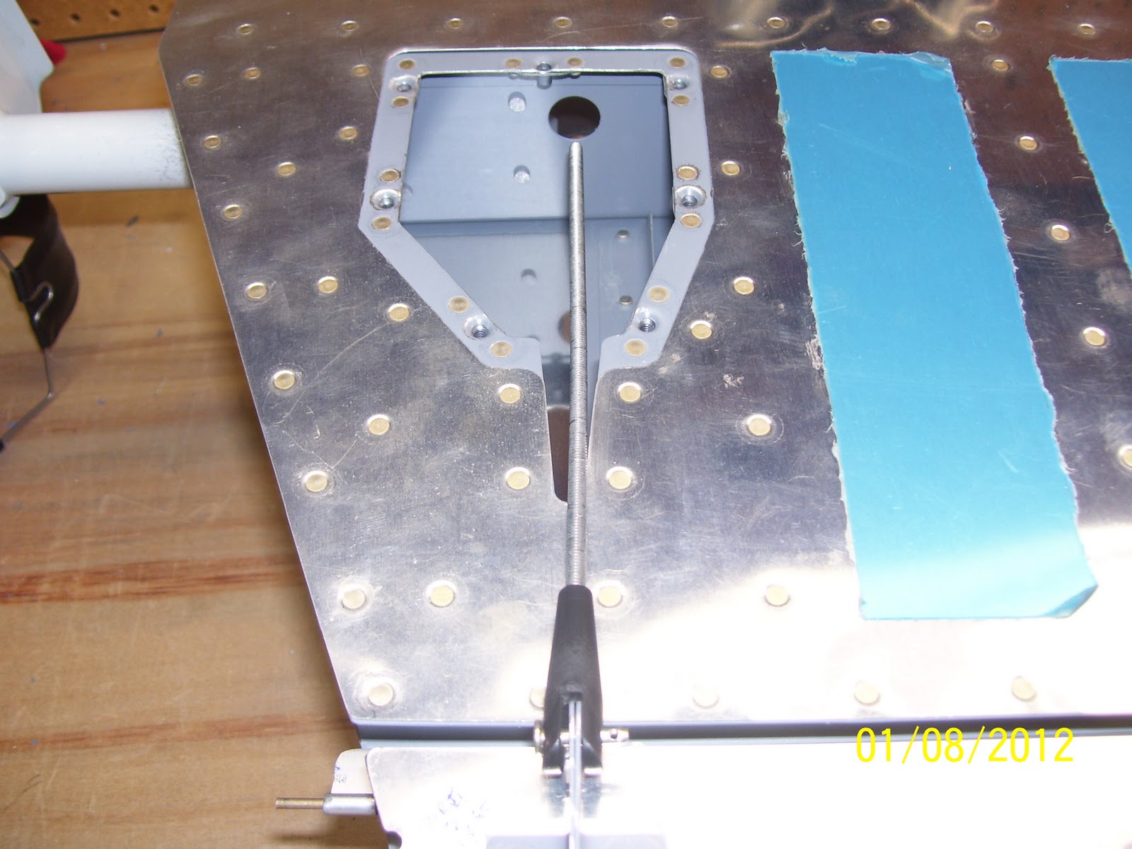
This next sequence of pics shows you what I ended up with after I remounted the trim servo to the brackets and installed the unit in the elevator. You guessed it - still off center. At least now I can see how far of center, and if I might still be able to trim some material away to clear it. The concern is maintaining correct edge distance of the rivets that are set along the same side. It turns out to be very close.


 You can see from the sharpee marks that I made how much material I would need to remove to clear the output shaft at its most extended range of travel. Guess I forgot to mention earlier that you want to fully extend the shaft of the trim servo using a 9 volt battery so that you can see the impact of the fully extended arm.
Now I get to decide - - trim the matieral and leave everything mounted as is, or reposition. I have already ordered a new cover plate from Van's, so I will contemplate what I want to do while I wait for the part to arrive.
- Leave the rod straight and trim away material from the elevator skin, support bracket, and cover plate to make room for the output shaft of the trim servo and the rod
- Center the position of the trim servo and then joggle or bend the rod over as far as necessary to align it with the control horn
- Center the trim servo, leave the rod straight, and bend the control horn to align everything.
I decided that option 3 is just not an option. Bending the control horn presents all sorts of possible fatigue and failure scenarios as far as I am concerned that I just won't do it. This comes mainly from a lot of RC airplane building experience where bending a control horn to a point where it is out of alignment with the hinge line of the control surface causes fatigue to the horn, the clevis pin, and the clevis, and may also put strain on the servo or on the hinge of the trim tab.
Option 2 is what many people have done, but others warn that bending the threaded rod causes stress points in the rod where the threads are forced closer together, and this may lead to failure of the rod - also not a good outcome.
So I decided to explore option one a bit further. One comment I received from another builder hinted that you might not know just how centered or uncentered everything is without putting it all together, mounting it in the elevator, and checking it then. This was sound advice adn is the main reason I decided to proceed, even though I knew that te rod was off center from where I expected it to be.
The following pics describe a very handy process that I learned from Steve Riffe. It basically involves trsansfering the position of the rod as it aligns with the control horn onto the trim servo cover plate, and then making a template on a piece of cardboard or similar material that contains the outline of the cover plate, and an exended line for the pushrod location, using the line marked on the cover plate as a reference.
It starts by screwing the cover plate into position, attaching the rod and one clevis to the trom tab control horn, laying the rod over the access plate, adn drawing a line a cross the top. This is the reference line that shows the position of of the rod as it enters the area where the trim servo will be located. Use a stright edge to transfer the line from the rod to the access plate:

Next carry the marks for the end of the reference line on the top of of the cover plate down the edges and then draw the same line across the bottom of the cover plate.
Turn the cover plate over so that the bottom faces up. Take a piece of carboard or similar that is large enough to transfer the line for the rod, position the bottom of the cover plate about half way off of the edge the cardboard, and trace the outline of the plate into the cardboard. The reason for tracing only half of it and not the whole thing will become apparent a bit later. IN this next pic, I show the cardboard traces of the cover plate, one in its entirety and the other half way down. Also note the line that I have extended from the cover plate onto the cardboard for the rod location.

Clamp the cover plate over the tracing, again - bottom side up.

Next, cleco the trim servo to the left and right mounting brackets, measure the offset distance (3/8 of an inch from the rear of the plate, and draw that line on the plate. This is where the back edge of the mounting brackets should sit on the cover plate. Take the trim servo assembly and place it on the cover plate. Align the servo output shaft and jack screw with the line drawn on the plate for the rod, then clamp the brackets in place on the cover plate as shown in the next photo:

This next one shows just how far off center the rod and the output arm of the servo is when compared to the rough opening in the cover plate. Not quite centered in the cutout hole:

Next I removed the trim servo from the brackets and drilled the rivet holes to #40. I used a sharpee to draw the outline of each flange of the mounting brackets so I could monitor their position while drilling. Sorry for the blurry pic, but you get the idea...

Remove the card board and reclamp the assembly to the drill board and drill the holes. Put clecoes right into the wood to hold the brackets in position while the remaining holes are drilled.

This next pic shows closeup of an additional short line that I drew. This is the reference line that Van's tells you to draw to align the trim servo. Basically, if you use this line, you will end up about 1/8 inch off in the other direction (on the other side of the rod exit hole. It is best to follow this exercise to find out exactly where the servo mounting brackets need to be positioned.

This next sequence of pics shows you what I ended up with after I remounted the trim servo to the brackets and installed the unit in the elevator. You guessed it - still off center. At least now I can see how far of center, and if I might still be able to trim some material away to clear it. The concern is maintaining correct edge distance of the rivets that are set along the same side. It turns out to be very close.


Now I get to decide - - trim the matieral and leave everything mounted as is, or reposition. I have already ordered a new cover plate from Van's, so I will contemplate what I want to do while I wait for the part to arrive.
Sunday, January 8, 2012
429 hours - continue trim tab spar riveting and fitting it to elevator
An awesome day of progress today on the trim tab. I started with the remaining two rivets that attach the trim tab skin, spar, and E717 and E718 trim tab control horn most forward rivets. I had to clamp the trim tab back down on the table, but this time I had to extend the end that contained the control horn out beyond the table to clear the horn assembly. I also had to change the yoke from the flange yoke to the standard 3 inch yoke, and perform another squeezer placement miracle in order to get the squeezer in position to set the E717 (longer) control horn. Two of the rivets that attach the control horn were still left unset, because these will be used to attach the root riblet after everything else has been completed.
Here is the trim tab clamped into place again:

 Next is the underside of the trim tab after setting the two most forward rivets attaching the control horn halves to the bottom of the trim tab skin. I needed t set two more rivets along the longer E717 part, and this meant that I would need to switch yokes, since you are now moving aft toward the small trailing edge of the trim tab. The flange yoke is too tall for this area.
 Here is a shot of the 3 inch yoke in position for setting the rivets on this side of the trim tab. The trick was that I needed to remove the 1/2 inch flat set on the bottom in order to position the squeezer into position on the inside flange of the E717 control horn, and then insert the rivet set into the squeezer AFTER is was slid into position. I could not leave the sets on the yoke and fit them up and over the control horns, so I had to do it this way. Not sure how everyone else has managed this, but that is what I did. Difficult and back breaking because you have to bend down to see everything, but it worked.
 The 1/8 x 1/2 inch flat set is on the top side behind the spar in the above pic, (setting the shop head) and the 1/2 inch long x 3/8 inch flat set is shown on the bottom (placed over the manufactured flsuh head of the rivet on the bottom of the skin).
Here is the inside pic after the first two rivets were set:(rotate this pic 90 degrees to the left. Stupid digital cameras!) The three rivets under my thumb holding the top skin up are the ones I am showing. The first one os the one on the very end that holds the corner of the skin to the spar, and the next two are the ones holding the control horn brackets in addition to the spar to the skin. I got these with the flange yoke and then switched over to the 3 inch yoke as I moved rearward.

Next is the bottom of the trim tab showing all the rivets that I set to hold the control horn brackets on. The clecoes show the remaining two holes that I am not riveting yet because the riblet still needs to be inserted, and it will also be attached to the rivets that go into these holes. the riblet won't go in until all the final fitting and trimming of the trim tab has been completed.
 With that completed, I moved on to the trial fitting of the trim tab to the elevator and the fitting and final drilling of the other half of the E721 hinge flange to the elevator. Per the plans, you start by ensuring that the first hole is 3/8 inch from the end of the hinge on the outboard side. I measured and drew a line. The other line you see that runs the span of the hinge was similar to the line that was drawn on the hinge half used on the trim tab to ensure that I maintained proper edge distance for the rivets.
Turns out that most folks end up drilling holes in slightly different position along the hinge that is attached to the elevator. this is because final fitting of the hinge to ensure that the trim tab lines are in sync with the rest of the elevator usually requires the hinge on the elevator side to be positioned slightly differently than straight down the middle. Mine was no exception to this. Even so, all the holes are still very close to the center line, so I was satisfied with them. Pics of the holes to follow....

This next pic shows my solution to what turned out to be a bit of a question for me. The plans say to clamp the elevator hinge and the trim tab assembly to the elevator. Unfortunately, if you try to attach the trim tab to the elevator, the only place you can apply a clamp to the elevator hinge is on the inboard side of the elevator whre you see my cleco clamo in the next pic. the only other place I found that you could "clamp" anything was at the trailing edge of the trim tab where it sits next to the elevator. I found this to be very awkward and not a very precise way to attach everything. The whole reason you are doing this is to find the final position of the elevator hinge that allows the trim tab to line up correctly with the trailing and inboard edges of the elevator. Then you are supposed to remove everything and final drill all the holes in the hinge. It all seemed very unprecise to me and I was worried about getting the alignment right and screwing up yet another part in the process if my drilled hinge holes were not correct.

Another thing to point out is the clearance between the edge of the trim tab and the elevator on the outboard edge. I had already marked the trim tab and pointed out in a previous post that I would need to significantly trim up this edge of the trim tab in order to allow it to fit properly next to the elevator. The plans require a minimum 3/32" clearance. This shot shows that after trimming the trailing edge of the trim tab down with the scotch brite wheel, I barely had a 1/64" clearance. between the two edges. At any rate is was enough to be able to tril fit the trim tab to the elevator. I will most likely remove additional material from the elevator to provide for the correct spacing.

Anyway, back to trila fitting the trim tab... Sometimes you come up with the most ingenious ways to solve a problem, using things that are right under your nose that you would not normally think could be used for a particular purpose, but they end up working quite well.
Problem: I had to remove the clamp in the above pic in oder to place a long 48 inch level along the back side of the elevator and the trim tab to ensure that the trailing edges of the two parts are in perfect alignment with each other, but if I removed the clamp, the trim tab would free fall and not maintain the alignment that I needed. I also needed a way to support the hinge on the outboard edge to I could align the elevator hinge. So how to sove this problem. I needed something to support the trim tab and keep it in relative alignment with the rest of the elevator while I worked with the level.
Solution: A nearby roll of paper towels, my 1/2 inch square sanding block, and a standard 1/4 inch wood wedge.....


The sanding block and the wedge were small enough to fit inside the flange of the E606PP rear elevator spar to suppor the hinge on the outboard edge and hold into relatively good position while I fit the trim tab. The paper towl provided just about the right height to support the trim tab after it was placed into position and the hinge pin was inserted into both hinge halves. This allowed me to be able to place the edge of my long level up against the trailing edge of the elevator and the trim tab to ensure that the alignment was correct. Then I was able to mark the holes on both ends of the elevator hinge with a sharpee so that I knew where they would need to be drilled.
Alignment of the TEs looks pretty darn good if I do say so myself:

With the TE alignment established, and the holes in the elevator hinge marked for drilling, time to drill some holes. I removed the hinge pin and the trim tab assembly, adn then used additional cleco clamps to hold the elevator hinge in place, using the markings I had made earlier on the hinge to ensure that the first holes would be drilled correctly, using the E701 elevator skin adn the E606PP holes as a drill guide per the plans. I started on the outboard end and drilled and clecoed every other hole in the hinge. Then I finished drilling all the remaining holes.


Next are some blurry pics attempting to show how the drilled holes in the hinge aligned with my original center line marking. You can see how the outboard ones are slightly off center, but still not bad...

 This one turned out a little bright, but IT MOVES!


Hinge pin reinstalled, checking the clearance between the trim tab and elevator outboard edges again. Will require a small amount of removal of the elevator edges:

and finally, turned elevator over on the bottom, fit the trim servo pushrod on the end of the trim tab control horn assembly, and checked the alignment with the exit hole for the pushrod end that will attach to the trim tab servo. I was prepared for this to be somewhat out of alignment with the end of the exit hole - just not quite this much out of alignment. This is a common problem that usually requires removal of some of the elevator skin in this area to provide proper clearance. Interesting that the pushrod is so far off to one side of the exit hole, but appears to be in perfect alignment with the center of the exit hole in the forward elevator spar, which is where the screw shaft and the trim tab wiring are supposed to fit into.

A fun day in the shop today, and the Broncos managed to pull out another miracle finish to move on in the playoffs today....A good day all around. Next is the fitting of the trim tab servo, riveting of the trim tab hinges, rolling of the elevator leading edges for both elevators, and a handfull of other tasks......
Here is the trim tab clamped into place again:


Here is the inside pic after the first two rivets were set:(rotate this pic 90 degrees to the left. Stupid digital cameras!) The three rivets under my thumb holding the top skin up are the ones I am showing. The first one os the one on the very end that holds the corner of the skin to the spar, and the next two are the ones holding the control horn brackets in addition to the spar to the skin. I got these with the flange yoke and then switched over to the 3 inch yoke as I moved rearward.

Next is the bottom of the trim tab showing all the rivets that I set to hold the control horn brackets on. The clecoes show the remaining two holes that I am not riveting yet because the riblet still needs to be inserted, and it will also be attached to the rivets that go into these holes. the riblet won't go in until all the final fitting and trimming of the trim tab has been completed.

Turns out that most folks end up drilling holes in slightly different position along the hinge that is attached to the elevator. this is because final fitting of the hinge to ensure that the trim tab lines are in sync with the rest of the elevator usually requires the hinge on the elevator side to be positioned slightly differently than straight down the middle. Mine was no exception to this. Even so, all the holes are still very close to the center line, so I was satisfied with them. Pics of the holes to follow....

This next pic shows my solution to what turned out to be a bit of a question for me. The plans say to clamp the elevator hinge and the trim tab assembly to the elevator. Unfortunately, if you try to attach the trim tab to the elevator, the only place you can apply a clamp to the elevator hinge is on the inboard side of the elevator whre you see my cleco clamo in the next pic. the only other place I found that you could "clamp" anything was at the trailing edge of the trim tab where it sits next to the elevator. I found this to be very awkward and not a very precise way to attach everything. The whole reason you are doing this is to find the final position of the elevator hinge that allows the trim tab to line up correctly with the trailing and inboard edges of the elevator. Then you are supposed to remove everything and final drill all the holes in the hinge. It all seemed very unprecise to me and I was worried about getting the alignment right and screwing up yet another part in the process if my drilled hinge holes were not correct.

Another thing to point out is the clearance between the edge of the trim tab and the elevator on the outboard edge. I had already marked the trim tab and pointed out in a previous post that I would need to significantly trim up this edge of the trim tab in order to allow it to fit properly next to the elevator. The plans require a minimum 3/32" clearance. This shot shows that after trimming the trailing edge of the trim tab down with the scotch brite wheel, I barely had a 1/64" clearance. between the two edges. At any rate is was enough to be able to tril fit the trim tab to the elevator. I will most likely remove additional material from the elevator to provide for the correct spacing.

Anyway, back to trila fitting the trim tab... Sometimes you come up with the most ingenious ways to solve a problem, using things that are right under your nose that you would not normally think could be used for a particular purpose, but they end up working quite well.
Problem: I had to remove the clamp in the above pic in oder to place a long 48 inch level along the back side of the elevator and the trim tab to ensure that the trailing edges of the two parts are in perfect alignment with each other, but if I removed the clamp, the trim tab would free fall and not maintain the alignment that I needed. I also needed a way to support the hinge on the outboard edge to I could align the elevator hinge. So how to sove this problem. I needed something to support the trim tab and keep it in relative alignment with the rest of the elevator while I worked with the level.
Solution: A nearby roll of paper towels, my 1/2 inch square sanding block, and a standard 1/4 inch wood wedge.....


The sanding block and the wedge were small enough to fit inside the flange of the E606PP rear elevator spar to suppor the hinge on the outboard edge and hold into relatively good position while I fit the trim tab. The paper towl provided just about the right height to support the trim tab after it was placed into position and the hinge pin was inserted into both hinge halves. This allowed me to be able to place the edge of my long level up against the trailing edge of the elevator and the trim tab to ensure that the alignment was correct. Then I was able to mark the holes on both ends of the elevator hinge with a sharpee so that I knew where they would need to be drilled.
Alignment of the TEs looks pretty darn good if I do say so myself:

With the TE alignment established, and the holes in the elevator hinge marked for drilling, time to drill some holes. I removed the hinge pin and the trim tab assembly, adn then used additional cleco clamps to hold the elevator hinge in place, using the markings I had made earlier on the hinge to ensure that the first holes would be drilled correctly, using the E701 elevator skin adn the E606PP holes as a drill guide per the plans. I started on the outboard end and drilled and clecoed every other hole in the hinge. Then I finished drilling all the remaining holes.


Next are some blurry pics attempting to show how the drilled holes in the hinge aligned with my original center line marking. You can see how the outboard ones are slightly off center, but still not bad...


Hinge pin reinstalled, checking the clearance between the trim tab and elevator outboard edges again. Will require a small amount of removal of the elevator edges:
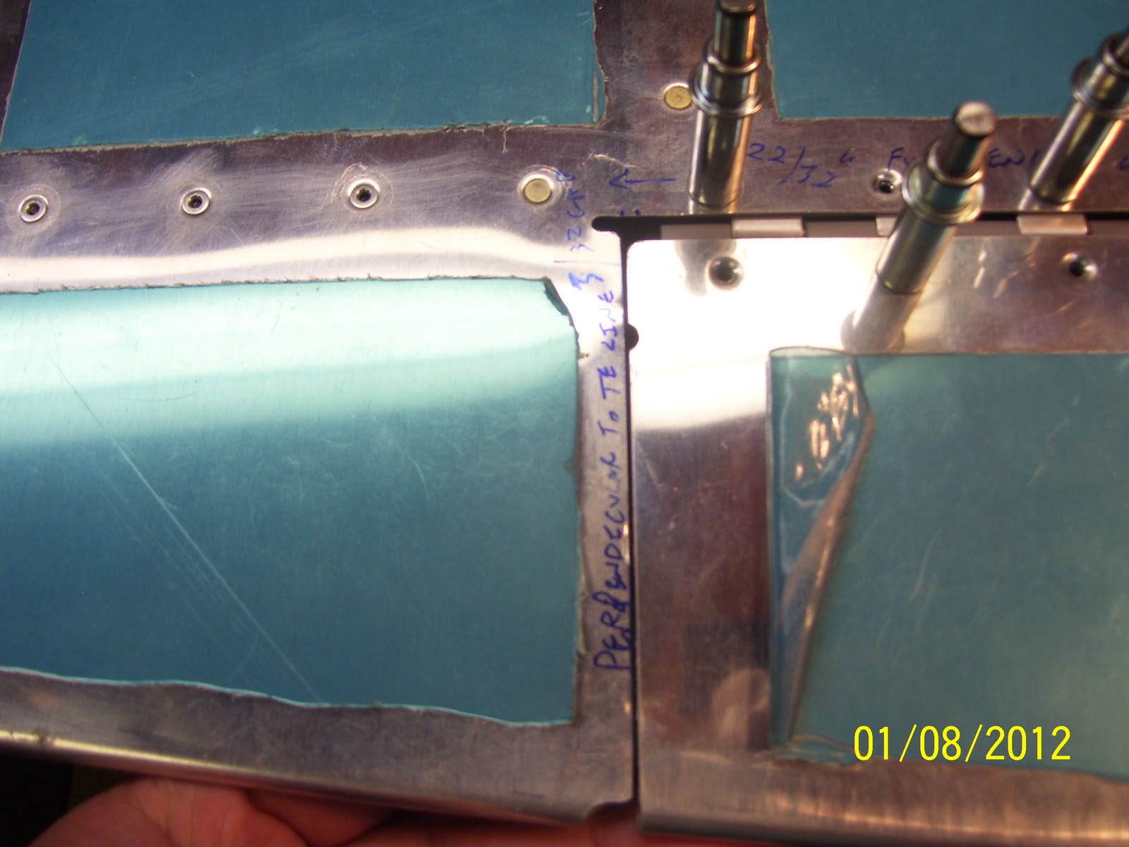
and finally, turned elevator over on the bottom, fit the trim servo pushrod on the end of the trim tab control horn assembly, and checked the alignment with the exit hole for the pushrod end that will attach to the trim tab servo. I was prepared for this to be somewhat out of alignment with the end of the exit hole - just not quite this much out of alignment. This is a common problem that usually requires removal of some of the elevator skin in this area to provide proper clearance. Interesting that the pushrod is so far off to one side of the exit hole, but appears to be in perfect alignment with the center of the exit hole in the forward elevator spar, which is where the screw shaft and the trim tab wiring are supposed to fit into.
A fun day in the shop today, and the Broncos managed to pull out another miracle finish to move on in the playoffs today....A good day all around. Next is the fitting of the trim tab servo, riveting of the trim tab hinges, rolling of the elevator leading edges for both elevators, and a handfull of other tasks......
Saturday, January 7, 2012
425 hours - finishing up elevator rivets and riveted bottom of trim tab
Editor's note on 1-17-2012. Originally I posted some pics of the position and type of rivet sets that I installed in my flange yoke that were incorrect. I have since edited those sections of this post to show the correct sets and their correct position in the flange yoke. Apologies to any builders following my blog if this led to any confusion.
So I seem to have some trouble adjusting the depth of my rivet sets in my hand squeezer. After setting the majority of of the top and bottom side rivets on the left elevator, I went back with my depth gage to check the rivets, and every one of them was set just a tad shy of where I normally like them. I have met some builders who state that the shop head of the rivet is supposed to sit just inside the hole, without any play, in order to determine if the shup head has been set correctly. Then I ahve attended classes, watched videos, adn read instructions for tools that state that the rivet head should never fit inside the hole, and this is the appraoch that I have always taken.
I am certain this will qualify as one of those never ending debate topics on VAF forums. IN any event, I needed to readjust the depth of my rivet sets and go back and squeeze each rivet again just a bit more to get them to ook the way I wanted. The problem arose from trying to check rivets on the top sides of the spars and ribs after squeezing them. My crummy progressive lense glasses end up giving me the perception that the rivets are set correctly as I check them with the gage, but when I flip the part over and check those same rivets that are now face up on the bottom (easier to see the gage sitting on the rivet), I see that all the shop heads are sliding inside the rivet hole of the gage.
Anyway, after getting that resolved, it was time to turn my attention to the trim tab. What an operation that turns out to be. This is yet another exercise of determining the correct positioning, clamping, tool selection, and technique to accomplish the job. I tried to take some pics that you don't normally see on most builders logs to help dispell some of the mystery behind how this works. So here we go....
First is my clamping setup. You supposed to rivet the trim tab spar to the bottom of the trim tab skin first. The spar is Z shaped, and requires either a flange yoke or a long extension back rivet set to accomplish this correctly. I chose to use the flange yoke technique. TO start, you need to clamp the bottom skin down flat on your bench. I used two small hobby sized bar clamps that were able to fit inside the ends of the trim tab skin, and also helped lift the top skin up just a bit, which you will need to do to fit the flange yoke inside to set the rivets. Note how the skin is raised up off of the top of the spar on the outboard end of the trim tab.
 Start with all bottom holes clecoed, and remove one from the end to start riveting. You basically rivet one hole and then move to the next one, removing one cleco at a time. this method worked out pretty well. TO get the skin to raise up far enough to get the yoke in there you need to put a wedge or piece of wood inside the skin to force the skin to open up just a bit. I used my trusty 1x2 blocks that have been with me since day one of the build as shown below:

If I had it to do over again I would have cut some wood to form a wedge, which would work a bit better than square blocks of wood like I used, but they still did the job. Next was deciding which rivet sets to use, and which way to install them in the yoke. I went through several girations of this, until I finally figured out what I needed as shown in the next pic:

SO I ended up using the 1/8 inch thick x 1/2 inch wide flat set on the bottom, or in the above pic it's on the left, and the 3/8 inch wide x 1/2 inch long flat set on the top of the yoke, or in the pic it is on the right. This allowed me to ensure that I had enough of the flat set on the bottom covering the flush head of the rivet, and the longer set on the top allowed me to reach behind the trim tab front spar and squeeze the rivet shaft down to the proper depth. It worked very well.
Next was trying to determine how I was going to keep the rivets in place, since they would need to be inserted from the bottom, based on the way that I ahve clamped everything to the bench. My first decision was to use back rivet tape to hold them into place. Seemed like a good idea, but the tape was not working out very well for me. This was most likely because I was still trying to figure out how to best position the squeezer, and during that time on the first rivet I messed up the tape, which caused the rivet to slip out.
So I decided to try another solution for this which up until now I had never really done before. I decided to pre-squeeze, or swell the rivets just a bot before inserting them into the rivet holes, to force them to stay in place once they were inserted. I had read about this technique, but had not had an opportunity to try it. First time for everything......
The process involves taking a rivet and inserting in between the two rivet sets in the squeezer, as show in the next pic. The tricky part is quezzing it down just far enough to allow it to still insert inato the hole, but tight enough to where it will remain in place and will not fall down or out of the hole. It does not take much to do this, and finding the right pressure to apply on the squeezer can be a bit of a challenge. After a couple of attempts I pretty much had it down to rough science:
 The set combination shown in the above pic is actually the reverse of the arrangement I used to set the rivets, so don't be confused by the reverse order shown here. Just center the rivet up between the two sets, and apply a small amount of pressure to swell up the rivet shaft just a bit. Then insert the rivet into the hole. It helps if the rivet is as much in the center of the rivet set as possible. I found that the rivets would sort of snap into position and stay there if the shaft was swelled just the right amount. If you swelled them too much the rivet would not go into the hole all the way and you would have to try another rivet with a little less pressure.
The next pic probably does the best job of showing how the squeezer needs to be positioned for this task. Yup another FAA shot to prove that I am the insane idiot that is actually building this thing, even it if it is only showing the bald spot on the top of my head. Yikes!
 The steps invlolved, at least the ones that I took, are as follows:
1. Started with rivet inserted into one hole, clecoes in all other bottom holes, working from the outboard or small end of the trim tab toward the inboard or root/large end. Why in that sequence? Because I wanted to tackle the hard holes first. The outboard holes are harder to rivet because the skin is much harder to left out of the way at the smaller end. Start with the sets slightly farther apart than needed so that you can determine the proper depth to set the rivets.
2. Lift the top skin up far enough to be able to see the shaft of the yoke as you slide it behind the spar web adn over the rivet shaft.
3. Slide the yoke into poistion over the rivet from the end, and gently apply pressure to the handles of the squeezer and watch the top head come down over the shaft of the rivet. Move the squeezer as needed so that the rivet shaft is centered as much as possible over the rivet shaft.
4. With the squeezer into position on the top, bend down and focus your attention on the bottom set which is over the flush head of the rivet and the bottom trim tab skin. Make certain that this rivet set is sitting flat over the skin and on the rivet head, and then squeeze a way. I found that I needed to use my left hand initially to hold the top skin back so that I could slide the squeezer into position with my right hand. Once I had enough pressure to just hold the top set in place over the rivet shaft, I could let go of the top trim tab skin, and use both hands to squeeze the rivet. This also helped ensure that the bottom set remained flat on the rivet head and the skin. This is the step you see me performing in the above pic.
5. Once the rivet is squeezed, take your left hand and hold the top skin up again so that you can remove the squeezer the same way it was inserted out the end of the trim tab.
6. Check the rivet t ensure it is set correctly. If not, adjust the depth of the sets and squeeze it again if necessary.
7. Remove the cleco for the very next hole, and start the process all over again.
Note that the squeezer handles are facing down, and not up. Took me a while to figure out that this is the way I needed to position it to squeeze these rivets.
First rivet is set successfully - YAY!

This is the starting position of the squeezer as you start to slide it into position. You can see why you need to use your left hand to hold up the skin in order to allow the top of the yoke to slide into position. It does take some force to position the yoke in place on this smaller end. It gets easier as you move toward the root end of the trim tab:

This next pic turned out blurry, but I am trying to show that when you get down to the last three rivets on the bottom, pay very close attention so you don't mess this up. You can set the very last rivet with the squeezer, but DO NOT set the next two rivets until the you have the E717 and E718 trim tab control horn brackets in position on the bottom of the trim tab. These holes will also require at least a 3-4 rivet instead of the 3-3.5 rivets used on the other holes. Since I am using riblets in the ends I also needed to wait until those are installed before I set bottom rivets number two and three from the root of the trim tab. I cannot install those permanently until the trim tab is final fitted into position on the elevator.
 It shows the last rivet installed (Squeezer was inserted from the root side for this last rivet due to the clecoes for the other two holes being in the way).
A nice line of rivets shown here - every one of them set successfully:

Next are a few pre-squeezed rivets that I ended up over squeezing just a bit. They would not fit into the holes, even after using my large mushroom flush set to try to push the rivet through the hole. So I used some pliers to grab the head of the rivet and pull it back out of the holes, and got a different rivet and tried again.
 Next is the trim tab bottom side. ALl rivets nice and flush to the skin. Glad I am almost done with these rivets. I was worried that I might mess up the skin while trying to set these, but it worked out fine.

Next is a little issue that I noted while browsing through Steve Riffe's builders log. The trim tab control horns attach to the bottom of the trim tab skin at the root. to try to prevent corrosion, the surface of the trim tab skin that mates to the two control horn halves should be primed or otherwise treated. I guess there have been reports that this is one of the areas for water to collect and where corrosion is most often found. So I tool the time to prime the surface of the skin where it contacts the parts for the control horn. Here I ahve masked it off for priming:
 And here is the skin all primed:

Lastly are some shots of the top side of the elevator after getting those rivets set. The clamps you see are holding the top of rear spar to the skin in preparation for the next step, which is to fit the other half of the trim tab hinge adn final fit the trim tab assembly to the elevator. After that is done, only the trim tab servo remains. Then I get to haul the horizontal stab down off the wall to assemble and trial fit the elevators - -I can hardly wait!!!!


So I seem to have some trouble adjusting the depth of my rivet sets in my hand squeezer. After setting the majority of of the top and bottom side rivets on the left elevator, I went back with my depth gage to check the rivets, and every one of them was set just a tad shy of where I normally like them. I have met some builders who state that the shop head of the rivet is supposed to sit just inside the hole, without any play, in order to determine if the shup head has been set correctly. Then I ahve attended classes, watched videos, adn read instructions for tools that state that the rivet head should never fit inside the hole, and this is the appraoch that I have always taken.
I am certain this will qualify as one of those never ending debate topics on VAF forums. IN any event, I needed to readjust the depth of my rivet sets and go back and squeeze each rivet again just a bit more to get them to ook the way I wanted. The problem arose from trying to check rivets on the top sides of the spars and ribs after squeezing them. My crummy progressive lense glasses end up giving me the perception that the rivets are set correctly as I check them with the gage, but when I flip the part over and check those same rivets that are now face up on the bottom (easier to see the gage sitting on the rivet), I see that all the shop heads are sliding inside the rivet hole of the gage.
Anyway, after getting that resolved, it was time to turn my attention to the trim tab. What an operation that turns out to be. This is yet another exercise of determining the correct positioning, clamping, tool selection, and technique to accomplish the job. I tried to take some pics that you don't normally see on most builders logs to help dispell some of the mystery behind how this works. So here we go....
First is my clamping setup. You supposed to rivet the trim tab spar to the bottom of the trim tab skin first. The spar is Z shaped, and requires either a flange yoke or a long extension back rivet set to accomplish this correctly. I chose to use the flange yoke technique. TO start, you need to clamp the bottom skin down flat on your bench. I used two small hobby sized bar clamps that were able to fit inside the ends of the trim tab skin, and also helped lift the top skin up just a bit, which you will need to do to fit the flange yoke inside to set the rivets. Note how the skin is raised up off of the top of the spar on the outboard end of the trim tab.


If I had it to do over again I would have cut some wood to form a wedge, which would work a bit better than square blocks of wood like I used, but they still did the job. Next was deciding which rivet sets to use, and which way to install them in the yoke. I went through several girations of this, until I finally figured out what I needed as shown in the next pic:

SO I ended up using the 1/8 inch thick x 1/2 inch wide flat set on the bottom, or in the above pic it's on the left, and the 3/8 inch wide x 1/2 inch long flat set on the top of the yoke, or in the pic it is on the right. This allowed me to ensure that I had enough of the flat set on the bottom covering the flush head of the rivet, and the longer set on the top allowed me to reach behind the trim tab front spar and squeeze the rivet shaft down to the proper depth. It worked very well.
Next was trying to determine how I was going to keep the rivets in place, since they would need to be inserted from the bottom, based on the way that I ahve clamped everything to the bench. My first decision was to use back rivet tape to hold them into place. Seemed like a good idea, but the tape was not working out very well for me. This was most likely because I was still trying to figure out how to best position the squeezer, and during that time on the first rivet I messed up the tape, which caused the rivet to slip out.
So I decided to try another solution for this which up until now I had never really done before. I decided to pre-squeeze, or swell the rivets just a bot before inserting them into the rivet holes, to force them to stay in place once they were inserted. I had read about this technique, but had not had an opportunity to try it. First time for everything......
The process involves taking a rivet and inserting in between the two rivet sets in the squeezer, as show in the next pic. The tricky part is quezzing it down just far enough to allow it to still insert inato the hole, but tight enough to where it will remain in place and will not fall down or out of the hole. It does not take much to do this, and finding the right pressure to apply on the squeezer can be a bit of a challenge. After a couple of attempts I pretty much had it down to rough science:

The next pic probably does the best job of showing how the squeezer needs to be positioned for this task. Yup another FAA shot to prove that I am the insane idiot that is actually building this thing, even it if it is only showing the bald spot on the top of my head. Yikes!

1. Started with rivet inserted into one hole, clecoes in all other bottom holes, working from the outboard or small end of the trim tab toward the inboard or root/large end. Why in that sequence? Because I wanted to tackle the hard holes first. The outboard holes are harder to rivet because the skin is much harder to left out of the way at the smaller end. Start with the sets slightly farther apart than needed so that you can determine the proper depth to set the rivets.
2. Lift the top skin up far enough to be able to see the shaft of the yoke as you slide it behind the spar web adn over the rivet shaft.
3. Slide the yoke into poistion over the rivet from the end, and gently apply pressure to the handles of the squeezer and watch the top head come down over the shaft of the rivet. Move the squeezer as needed so that the rivet shaft is centered as much as possible over the rivet shaft.
4. With the squeezer into position on the top, bend down and focus your attention on the bottom set which is over the flush head of the rivet and the bottom trim tab skin. Make certain that this rivet set is sitting flat over the skin and on the rivet head, and then squeeze a way. I found that I needed to use my left hand initially to hold the top skin back so that I could slide the squeezer into position with my right hand. Once I had enough pressure to just hold the top set in place over the rivet shaft, I could let go of the top trim tab skin, and use both hands to squeeze the rivet. This also helped ensure that the bottom set remained flat on the rivet head and the skin. This is the step you see me performing in the above pic.
5. Once the rivet is squeezed, take your left hand and hold the top skin up again so that you can remove the squeezer the same way it was inserted out the end of the trim tab.
6. Check the rivet t ensure it is set correctly. If not, adjust the depth of the sets and squeeze it again if necessary.
7. Remove the cleco for the very next hole, and start the process all over again.
Note that the squeezer handles are facing down, and not up. Took me a while to figure out that this is the way I needed to position it to squeeze these rivets.
First rivet is set successfully - YAY!


This next pic turned out blurry, but I am trying to show that when you get down to the last three rivets on the bottom, pay very close attention so you don't mess this up. You can set the very last rivet with the squeezer, but DO NOT set the next two rivets until the you have the E717 and E718 trim tab control horn brackets in position on the bottom of the trim tab. These holes will also require at least a 3-4 rivet instead of the 3-3.5 rivets used on the other holes. Since I am using riblets in the ends I also needed to wait until those are installed before I set bottom rivets number two and three from the root of the trim tab. I cannot install those permanently until the trim tab is final fitted into position on the elevator.

A nice line of rivets shown here - every one of them set successfully:

Next are a few pre-squeezed rivets that I ended up over squeezing just a bit. They would not fit into the holes, even after using my large mushroom flush set to try to push the rivet through the hole. So I used some pliers to grab the head of the rivet and pull it back out of the holes, and got a different rivet and tried again.


Next is a little issue that I noted while browsing through Steve Riffe's builders log. The trim tab control horns attach to the bottom of the trim tab skin at the root. to try to prevent corrosion, the surface of the trim tab skin that mates to the two control horn halves should be primed or otherwise treated. I guess there have been reports that this is one of the areas for water to collect and where corrosion is most often found. So I tool the time to prime the surface of the skin where it contacts the parts for the control horn. Here I ahve masked it off for priming:


Lastly are some shots of the top side of the elevator after getting those rivets set. The clamps you see are holding the top of rear spar to the skin in preparation for the next step, which is to fit the other half of the trim tab hinge adn final fit the trim tab assembly to the elevator. After that is done, only the trim tab servo remains. Then I get to haul the horizontal stab down off the wall to assemble and trial fit the elevators - -I can hardly wait!!!!

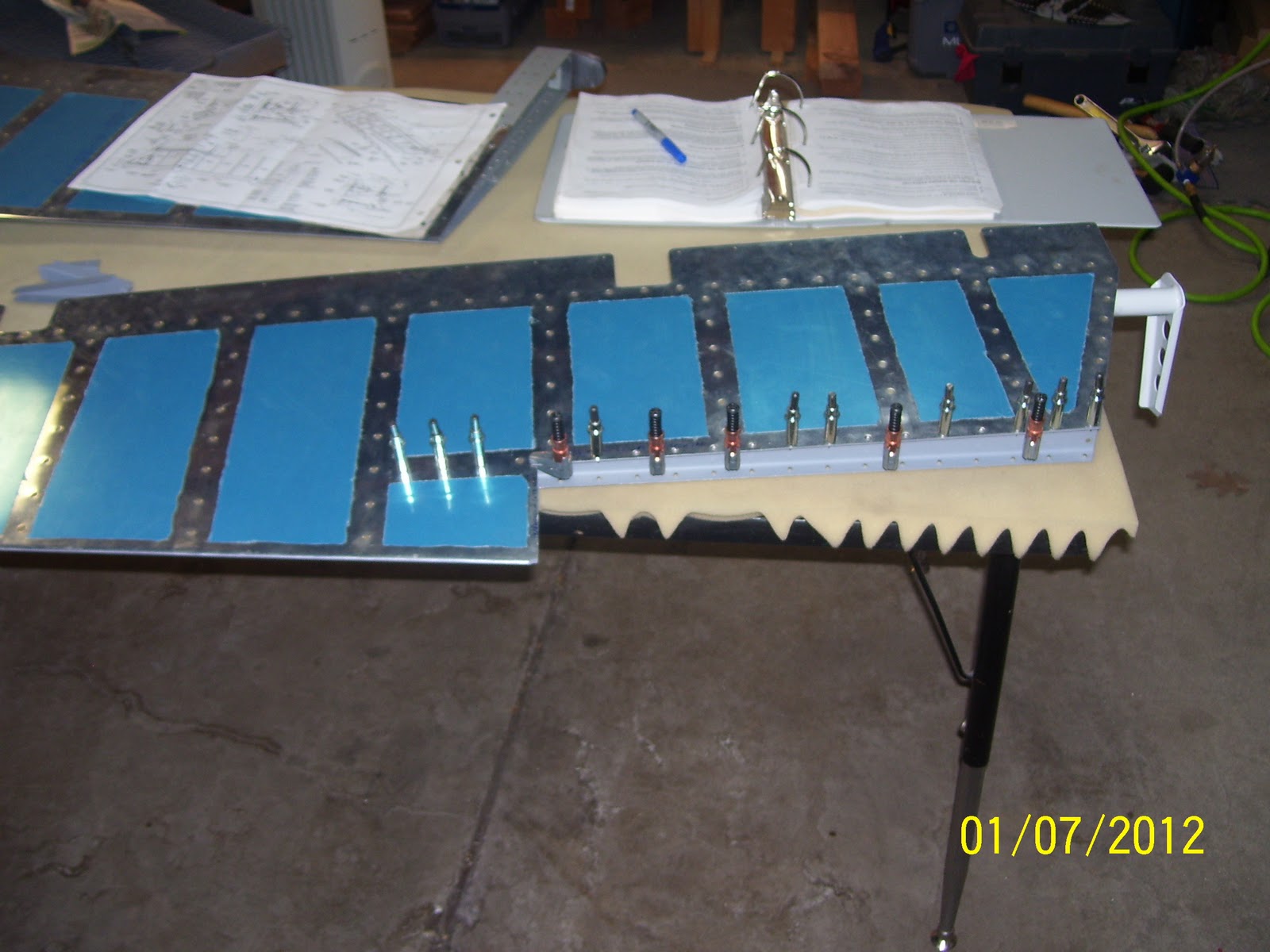

Subscribe to:
Posts (Atom)