Here is the trim tab clamped into place again:


Here is the inside pic after the first two rivets were set:(rotate this pic 90 degrees to the left. Stupid digital cameras!) The three rivets under my thumb holding the top skin up are the ones I am showing. The first one os the one on the very end that holds the corner of the skin to the spar, and the next two are the ones holding the control horn brackets in addition to the spar to the skin. I got these with the flange yoke and then switched over to the 3 inch yoke as I moved rearward.

Next is the bottom of the trim tab showing all the rivets that I set to hold the control horn brackets on. The clecoes show the remaining two holes that I am not riveting yet because the riblet still needs to be inserted, and it will also be attached to the rivets that go into these holes. the riblet won't go in until all the final fitting and trimming of the trim tab has been completed.

Turns out that most folks end up drilling holes in slightly different position along the hinge that is attached to the elevator. this is because final fitting of the hinge to ensure that the trim tab lines are in sync with the rest of the elevator usually requires the hinge on the elevator side to be positioned slightly differently than straight down the middle. Mine was no exception to this. Even so, all the holes are still very close to the center line, so I was satisfied with them. Pics of the holes to follow....

This next pic shows my solution to what turned out to be a bit of a question for me. The plans say to clamp the elevator hinge and the trim tab assembly to the elevator. Unfortunately, if you try to attach the trim tab to the elevator, the only place you can apply a clamp to the elevator hinge is on the inboard side of the elevator whre you see my cleco clamo in the next pic. the only other place I found that you could "clamp" anything was at the trailing edge of the trim tab where it sits next to the elevator. I found this to be very awkward and not a very precise way to attach everything. The whole reason you are doing this is to find the final position of the elevator hinge that allows the trim tab to line up correctly with the trailing and inboard edges of the elevator. Then you are supposed to remove everything and final drill all the holes in the hinge. It all seemed very unprecise to me and I was worried about getting the alignment right and screwing up yet another part in the process if my drilled hinge holes were not correct.

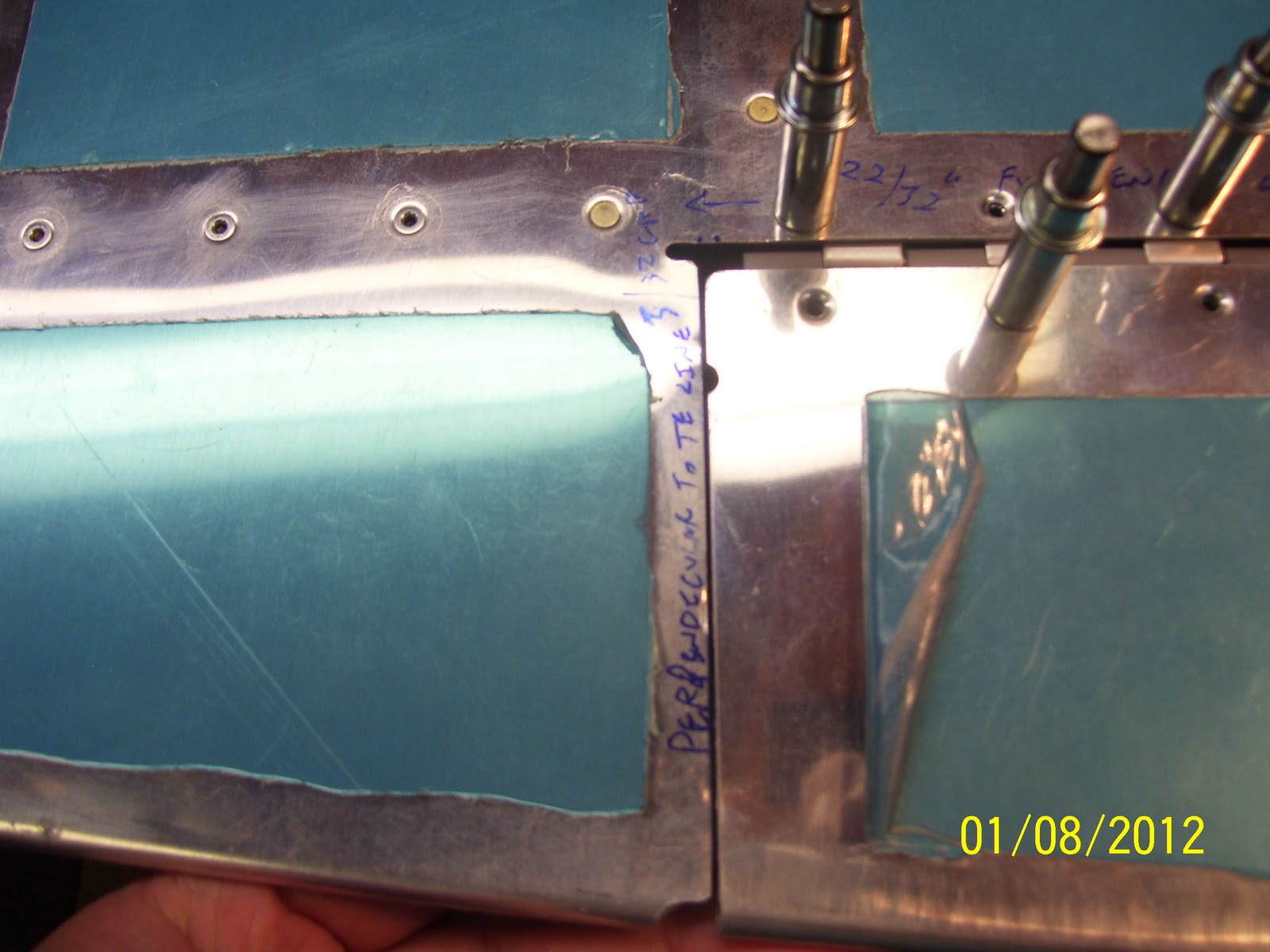
Another thing to point out is the clearance between the edge of the trim tab and the elevator on the outboard edge. I had already marked the trim tab and pointed out in a previous post that I would need to significantly trim up this edge of the trim tab in order to allow it to fit properly next to the elevator. The plans require a minimum 3/32" clearance. This shot shows that after trimming the trailing edge of the trim tab down with the scotch brite wheel, I barely had a 1/64" clearance. between the two edges. At any rate is was enough to be able to tril fit the trim tab to the elevator. I will most likely remove additional material from the elevator to provide for the correct spacing.

Anyway, back to trila fitting the trim tab... Sometimes you come up with the most ingenious ways to solve a problem, using things that are right under your nose that you would not normally think could be used for a particular purpose, but they end up working quite well.
Problem: I had to remove the clamp in the above pic in oder to place a long 48 inch level along the back side of the elevator and the trim tab to ensure that the trailing edges of the two parts are in perfect alignment with each other, but if I removed the clamp, the trim tab would free fall and not maintain the alignment that I needed. I also needed a way to support the hinge on the outboard edge to I could align the elevator hinge. So how to sove this problem. I needed something to support the trim tab and keep it in relative alignment with the rest of the elevator while I worked with the level.
Solution: A nearby roll of paper towels, my 1/2 inch square sanding block, and a standard 1/4 inch wood wedge.....


The sanding block and the wedge were small enough to fit inside the flange of the E606PP rear elevator spar to suppor the hinge on the outboard edge and hold into relatively good position while I fit the trim tab. The paper towl provided just about the right height to support the trim tab after it was placed into position and the hinge pin was inserted into both hinge halves. This allowed me to be able to place the edge of my long level up against the trailing edge of the elevator and the trim tab to ensure that the alignment was correct. Then I was able to mark the holes on both ends of the elevator hinge with a sharpee so that I knew where they would need to be drilled.
Alignment of the TEs looks pretty darn good if I do say so myself:

With the TE alignment established, and the holes in the elevator hinge marked for drilling, time to drill some holes. I removed the hinge pin and the trim tab assembly, adn then used additional cleco clamps to hold the elevator hinge in place, using the markings I had made earlier on the hinge to ensure that the first holes would be drilled correctly, using the E701 elevator skin adn the E606PP holes as a drill guide per the plans. I started on the outboard end and drilled and clecoed every other hole in the hinge. Then I finished drilling all the remaining holes.


Next are some blurry pics attempting to show how the drilled holes in the hinge aligned with my original center line marking. You can see how the outboard ones are slightly off center, but still not bad...


Hinge pin reinstalled, checking the clearance between the trim tab and elevator outboard edges again. Will require a small amount of removal of the elevator edges:
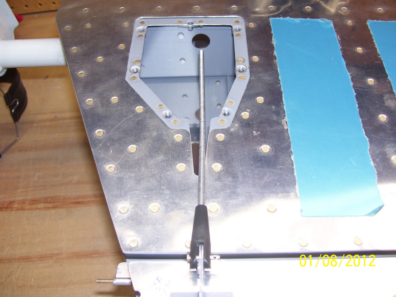
and finally, turned elevator over on the bottom, fit the trim servo pushrod on the end of the trim tab control horn assembly, and checked the alignment with the exit hole for the pushrod end that will attach to the trim tab servo. I was prepared for this to be somewhat out of alignment with the end of the exit hole - just not quite this much out of alignment. This is a common problem that usually requires removal of some of the elevator skin in this area to provide proper clearance. Interesting that the pushrod is so far off to one side of the exit hole, but appears to be in perfect alignment with the center of the exit hole in the forward elevator spar, which is where the screw shaft and the trim tab wiring are supposed to fit into.
A fun day in the shop today, and the Broncos managed to pull out another miracle finish to move on in the playoffs today....A good day all around. Next is the fitting of the trim tab servo, riveting of the trim tab hinges, rolling of the elevator leading edges for both elevators, and a handfull of other tasks......
No comments:
Post a Comment