As I anticipated, I have NOT been able to devote much time to the build over past couple of weeks because I needed to focus on preparing for the long 2000 mile road trip (1000 miles each way) to Airventure in Oshkosh Wisconsin. This will be year number 4 for me, and more importantly it is the fourth year in a row that I will make the pilgrimage and attend the entire event. So many others are unable to attend the whole thing, and I feel truly blessed to be able to experience it each and every day of the week-long event. Even more important is that my son will be attending the event with me again this year.
I have had to spend some quality time taking care of my home away from home, and I am happy to say that the preparations are almost complete. I usually end up having to amke at least some kind of water system repair from the previous year to my trailer. Maybe one day I will learn how to properly winterize everything, but until then, water system repairs are just part of the norm for me. It was actually not too bad this time - my 23 year old bathroom faucet valves finally decided to stop working, I found another one at HD for 11 bucks to replace it. Then I had a plastic P-trap drain part that was leaking along the seam. My dad offered up a fantastic remedy by using some of that rubber - in - a - spray can stuff to stop the leak, and it seems to have actually worked. I may have to remember that if I ever develop a leak in the airplane someday.
So far the extended weather forecasts for the Wisconsin area look very promising, adn are reminiscent of every other year I have attended excet for 2010, with temps in the comfortable 70s and 80s. VAF has already organized a gathering after the opening day Steve Miller Band concert, and I can't wait to attend that. My week is already chalked full of activities, including banquets, forums, workshops, adn just walking around gawking at airplanes for hours. Truly heaven on earth as far as I am concerned.
As for the build, I will probably be able to finish straightening and deburring the ribs, and might even be able to start match drilling some of them to the spar, but that will be about it before it is time to depart for Oshkosh. For those of you Attending, I will see you there. For those of you following my blog that have never been - you really have to do this at least once in your lifetime. It is probably the most positive experience I have ever had in my life, and I am almost to a point where I cannot imagine my life without it and the wonderful support from the EAA.
Wednesday, July 11, 2012
Sunday, July 1, 2012
Attended My First Engine Hanging Party
Last night I attended my very first aircraft engine hanging "party" at Ron Duren's house. It is traditionally called a party, but the reality is that the "party" did not begin until after all the actual work to hang the brand new Aerosport Power IO-375 engine was completed. It took about an hour and 45 minutes to complete - a little longer than expected, but we still got it done. Ron, thanks for inviting me to participate, and congrats on your newly mounted engine.
I had intended on taking a lot of video to document the process involved in performing this task, as I truly expect to be doing the same thing in a couple of years. Instead, I found myself highly involved in the process from the very beginning, and I ended up being very much "hands on" throughout most of the event, so unfortunately no video was captured. What I did come away with was a ton of pictures after the deed was done.
This engine is a 4 cylinder, fuel injected engine that generates close to 190 horsepower. It was extremely beneficial for me to be able to get a close up view of the components that make up this engine. I was able to see where the magnetos, fuel pump, prop governer, oil filter, Fuel distribution spider, and fuel control module are installed, as well as the oil fill/dipstick, alternator, starter, spark plugs, exhaust, and intake ports were installed as well. It was one of the few times I ahve been able to see a reciprocating aircraft engine completely out in the open, with no cowls or wires or tubes in the way.
The process actually took about an hour and a half, with jokes and speculation coming from the gallery of others in attendance that we should be able to hang this 300 pound beast in about 10 minutes to a half hour. My personal understanding of this from what I had read previously was that about an hour is usually what it takes to get everything installed on the engine mount.
Here is a shot of the installed engine. Ron had it painted red, and also had his engine mount powder coated the same color. SO what color do you think is primary for Ron's airplane? If you guessed RED, you are correct.

I guess I found it rather ironic that we were doing this in 100 degree heat, with wild fires burning all around us for weeks, with heavy smoke in the air, and here we are, hanging a fire-engine-red airplane engine on an airplane. I'm not really a red kind of person, but I will admit that this engine did look very beautiful with everything all painted and looking shiny and new. I am told that this engine will set you back about $31,000.00, with that and the prop being the two most expensive parts of this process, with avionics following close behind.
The engine mount is a special type of engine mount that is known as a dynafocal - 2 engine mount.There are 4 mount points on each of the 4 corners of the engine block, all of which are at specifc angles to the engine block. The actual engine mounts are also a special type of mount, called a Lord mount or something like that. The mounts are basically large round rubber disks that are inserted into receptacles in the engine mount, not unlike some engine mounts that are used for larger Radio Control Model engines. There are 3 main pieces to each engine mount, an outer and inner disk, and then in the middle on one side is an ellongated, egg or football shapped rubber insert. The mounting bolt inserts through the aft side of the engine mount, through the holes in the inner disk, then in the insert, and finally through the outer disk and through the mounting hole on the engine. There is also a specific order of the position of reach disk which is basically reversed between the top and bottom engine mounts.
Then apparently there is also a recommended order for inserting the bolts through the engine mounts. You start with the top right, then the top left, and the bottom right, and finally the bottom left mount. There is also a set of washers that must be inserted in the proper locations.
The process began by removing the mounting bolts for two large metal support brackets that the engine was mounted on for shipping. The engine had been on the hoist ever since Ron brought it home. After the shipping mounts were removed, the engine was raised on the hoist. The first area of concern was getting the magnetos and the fuel pump safely inside the engine mount. This whole process works well with about 3 people. One on each side of the engine and one on the hoist. We were able to maneuver the back of the engine so that the fuel pump and magnetos cleared the mounting bracket, and then we started aligning the bolt holes on the engine with the holes on the mounts.
Here is shot of the hoist that was used to lift the engine in place:

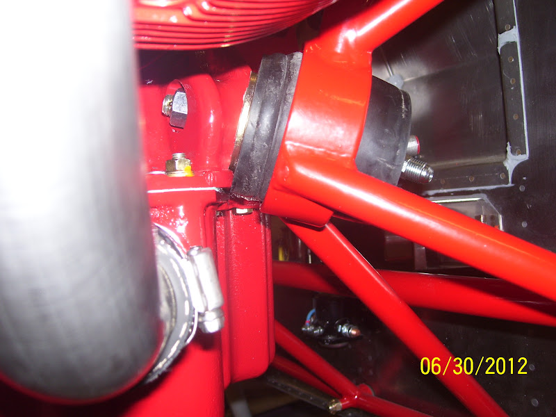
This next pic clearly shows the bottom left engine mount assembly. The top bolts managed to get inserted into the mounting holes with a little coaxing and pounding with a rubber mallet, and the bottom right bolt was also eventually inserted in the hole. The problem - and the source of about 45 minutes worth of difficulties, came when we tried to insert the bottom left bolt into the mount. The holes were anywhere from a full bolt width to a half bolt width off, and no matter what we tried we could not get this hole to line up.


The key to the solution came when I realized that the bottom of the outer rubber engine mount disk on that side was hitting the bottom of the oil sump casing. This was why the hole would not line up. Then somebody else finally realized that the reason that was happening was because the large washers were not in the proper position on the bottom mounting brackets.The thick large washers actually go between the engine and the outer engine mount disk on the bottom engine mounts, but go on the inner engine mount disks and the bolt head on the upper engine mounts. Click on the pics to get a larger, more detailed view. you can see the washer in the above pic, as well as the edge of the oil sump in relation to the rubber disk. The washer allowed the disk to just clear the casing of the oil sump, and this then allowed the engine mounting holes to line up correctly after loosening the nuts from the other bolts and raising the engine a bit more. The key was that we were able to raise the engine a bit more because the bottom left engine mount disk was allowed to clear the oil sump flange after the washer was properly placed into position.
Here is closeup of the top left engine mount:

Note the castlated nut. Each of the mounting bolts is allowed to turm in the mount due to vibration and shock absorbing affects of the engine mount. SO each bolt has a hole drilled through the tip at a specific location on the bolt, and the nut is screwed down and a cotter pin inserted throught bolt hole, trapping the nut so it cannot turn inward or outward. ANother interesting thing I learned about the engine mounts is that there is no torqueing involved. These engine mounts basically have an inner insert with the metal shaft, and my understanding is that you simply screw each bolt down on the nut until you feel it "bottom out" on the shaft of the inner insert. At that point the engine mounts are properly compressed, and the bolt is screwed down to the proper position.
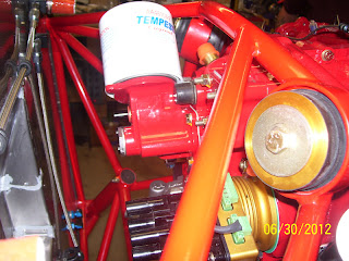
Here is shot that includes the top side of the top left engine mount and the oil filter, which by the way was also removed before we began the process of pushing the engine closer to the engine mounts when we began the process.

Next is a pic from the right side that shows P mags which are think are electronic ignition magnetos that are utilized to provide the spark to two sets of spark plugs.Also shown is a shot of the upper right engine mount and the oil filter
Next is a shot of the engine-driven fuel pump and the firewall:
 And finally a view from the front:

I took several other shots of various components, but sadly many of them turned out blurry. I get so damned pissed off at digital cameras every so often. Sometimes technology is not the best thing on the planet. Anyway, I am NOT going to post those at this time. Just wanted to give an idea of the engine mounting process and capture some of the issues and difficulties and tips and tricks to making this a success. It also felt kind of good to be able to be the one that initially identified the problem area for the final engine mounting bolt that allowed to figure out the problem, get it resolved, and finish mounting a very nice looking aircraft engine. Way to go Ron!
I had intended on taking a lot of video to document the process involved in performing this task, as I truly expect to be doing the same thing in a couple of years. Instead, I found myself highly involved in the process from the very beginning, and I ended up being very much "hands on" throughout most of the event, so unfortunately no video was captured. What I did come away with was a ton of pictures after the deed was done.
This engine is a 4 cylinder, fuel injected engine that generates close to 190 horsepower. It was extremely beneficial for me to be able to get a close up view of the components that make up this engine. I was able to see where the magnetos, fuel pump, prop governer, oil filter, Fuel distribution spider, and fuel control module are installed, as well as the oil fill/dipstick, alternator, starter, spark plugs, exhaust, and intake ports were installed as well. It was one of the few times I ahve been able to see a reciprocating aircraft engine completely out in the open, with no cowls or wires or tubes in the way.
The process actually took about an hour and a half, with jokes and speculation coming from the gallery of others in attendance that we should be able to hang this 300 pound beast in about 10 minutes to a half hour. My personal understanding of this from what I had read previously was that about an hour is usually what it takes to get everything installed on the engine mount.
Here is a shot of the installed engine. Ron had it painted red, and also had his engine mount powder coated the same color. SO what color do you think is primary for Ron's airplane? If you guessed RED, you are correct.

I guess I found it rather ironic that we were doing this in 100 degree heat, with wild fires burning all around us for weeks, with heavy smoke in the air, and here we are, hanging a fire-engine-red airplane engine on an airplane. I'm not really a red kind of person, but I will admit that this engine did look very beautiful with everything all painted and looking shiny and new. I am told that this engine will set you back about $31,000.00, with that and the prop being the two most expensive parts of this process, with avionics following close behind.
The engine mount is a special type of engine mount that is known as a dynafocal - 2 engine mount.There are 4 mount points on each of the 4 corners of the engine block, all of which are at specifc angles to the engine block. The actual engine mounts are also a special type of mount, called a Lord mount or something like that. The mounts are basically large round rubber disks that are inserted into receptacles in the engine mount, not unlike some engine mounts that are used for larger Radio Control Model engines. There are 3 main pieces to each engine mount, an outer and inner disk, and then in the middle on one side is an ellongated, egg or football shapped rubber insert. The mounting bolt inserts through the aft side of the engine mount, through the holes in the inner disk, then in the insert, and finally through the outer disk and through the mounting hole on the engine. There is also a specific order of the position of reach disk which is basically reversed between the top and bottom engine mounts.
Then apparently there is also a recommended order for inserting the bolts through the engine mounts. You start with the top right, then the top left, and the bottom right, and finally the bottom left mount. There is also a set of washers that must be inserted in the proper locations.
The process began by removing the mounting bolts for two large metal support brackets that the engine was mounted on for shipping. The engine had been on the hoist ever since Ron brought it home. After the shipping mounts were removed, the engine was raised on the hoist. The first area of concern was getting the magnetos and the fuel pump safely inside the engine mount. This whole process works well with about 3 people. One on each side of the engine and one on the hoist. We were able to maneuver the back of the engine so that the fuel pump and magnetos cleared the mounting bracket, and then we started aligning the bolt holes on the engine with the holes on the mounts.
Here is shot of the hoist that was used to lift the engine in place:

This next pic clearly shows the bottom left engine mount assembly. The top bolts managed to get inserted into the mounting holes with a little coaxing and pounding with a rubber mallet, and the bottom right bolt was also eventually inserted in the hole. The problem - and the source of about 45 minutes worth of difficulties, came when we tried to insert the bottom left bolt into the mount. The holes were anywhere from a full bolt width to a half bolt width off, and no matter what we tried we could not get this hole to line up.

The key to the solution came when I realized that the bottom of the outer rubber engine mount disk on that side was hitting the bottom of the oil sump casing. This was why the hole would not line up. Then somebody else finally realized that the reason that was happening was because the large washers were not in the proper position on the bottom mounting brackets.The thick large washers actually go between the engine and the outer engine mount disk on the bottom engine mounts, but go on the inner engine mount disks and the bolt head on the upper engine mounts. Click on the pics to get a larger, more detailed view. you can see the washer in the above pic, as well as the edge of the oil sump in relation to the rubber disk. The washer allowed the disk to just clear the casing of the oil sump, and this then allowed the engine mounting holes to line up correctly after loosening the nuts from the other bolts and raising the engine a bit more. The key was that we were able to raise the engine a bit more because the bottom left engine mount disk was allowed to clear the oil sump flange after the washer was properly placed into position.
Here is closeup of the top left engine mount:

Note the castlated nut. Each of the mounting bolts is allowed to turm in the mount due to vibration and shock absorbing affects of the engine mount. SO each bolt has a hole drilled through the tip at a specific location on the bolt, and the nut is screwed down and a cotter pin inserted throught bolt hole, trapping the nut so it cannot turn inward or outward. ANother interesting thing I learned about the engine mounts is that there is no torqueing involved. These engine mounts basically have an inner insert with the metal shaft, and my understanding is that you simply screw each bolt down on the nut until you feel it "bottom out" on the shaft of the inner insert. At that point the engine mounts are properly compressed, and the bolt is screwed down to the proper position.
Here is shot that includes the top side of the top left engine mount and the oil filter, which by the way was also removed before we began the process of pushing the engine closer to the engine mounts when we began the process.

Next is a pic from the right side that shows P mags which are think are electronic ignition magnetos that are utilized to provide the spark to two sets of spark plugs.Also shown is a shot of the upper right engine mount and the oil filter

Next is a shot of the engine-driven fuel pump and the firewall:


I took several other shots of various components, but sadly many of them turned out blurry. I get so damned pissed off at digital cameras every so often. Sometimes technology is not the best thing on the planet. Anyway, I am NOT going to post those at this time. Just wanted to give an idea of the engine mounting process and capture some of the issues and difficulties and tips and tricks to making this a success. It also felt kind of good to be able to be the one that initially identified the problem area for the final engine mounting bolt that allowed to figure out the problem, get it resolved, and finish mounting a very nice looking aircraft engine. Way to go Ron!
Subscribe to:
Posts (Atom)