Sunday, February 27, 2011

230 hours on the hobbs. Bent the rudder trailing edge today!

After literally weeks of fretting over everything that needed to be done to ensure that the bending of the trailing edge of the rudder was completed correctly, I am happy to report that with additional assistance and info provided by Steve Riffe, and personal assistance from another fellow RV 8  builder Bob Markert and his wife Mary, the rudder has finally been bent successfully.

The sequence of events over the past week was basically:
1. Secured the bending brake to the work bench by screwing it down onto te bench from underneath. The clamps are simply holding one of my flat boards on top of the brake after I had screwed it down on the bench So that I had a place to set the rudder to keep it flat. Don't be confused by this pic - the clamps have nothing to do with the bending brake, since it has already been screwed down from underneath, as the next pic shows.


2. Removed additional vinyl covering and prepared Leading Edge surfaces for primer. This was somwhat problematic for me because none of the holes in the leading edge have been drilled yet since the trailing edge has not been bent into its final position. It is almost pointless to prime a surface if you are going to have to remove material and then re-prime it later, so I did some more masking and scuffing in areas that would be difficult to get to after the rudder is bent, and will wait until later to apply the primer. This process took quite a bit of time to work through last week. I also needed to remove the vinyl from the outer TE of the rudder before performing the bend, and also from the inside as well. Make sure you do this, otherwise the vinyl may interfere with correctly bending the aluminum.


3. Decided to empty the work bench and move it away from the wall so that it would be easier to view the edges of the rudder while it was being bent. Man is there a lot of stuff under there! I was able to do some early spring cleaning after moving the bench, and take inventory of all my spare wood and other items, so it was good to do this for several other easons as well.


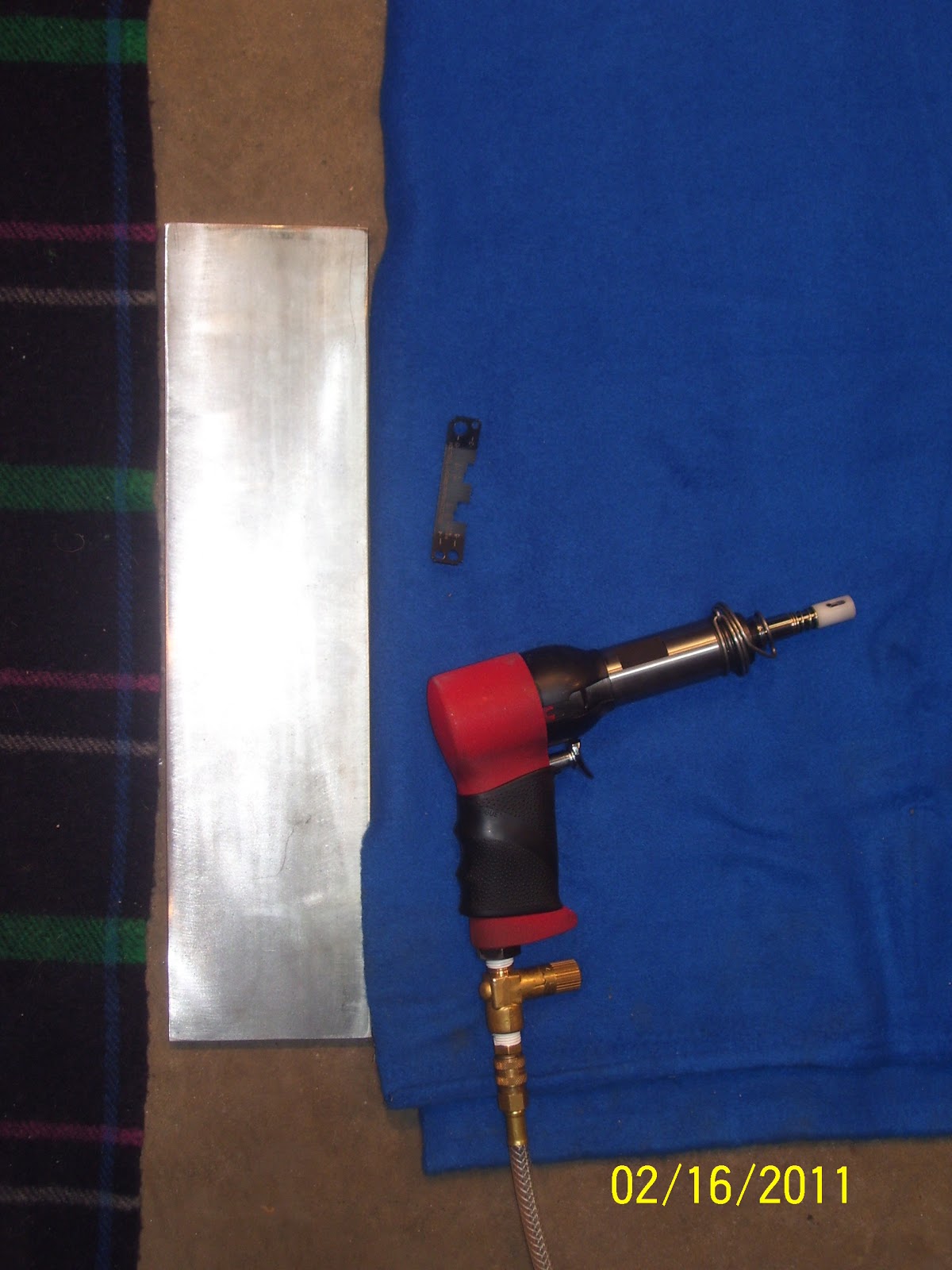
4. Had to fabricate a bunch of parts out of stock aluminum sheet per the plans- namely the two metal attach strips for the bottom fiberglass fairing of the rudder, a spacer or shim for the steering support assembly that attaches to the bottom of the front spar, and the support bracket that basically acts like a truss to strengthen the forward spar and the bottom rib where all the rudder cables will be attached. This area needs additional support, so it is beefed up quite a bit to handle the forces and loads that will be experienced when applying the push/pull action of the rudder pedals. This will happen mostly during takeoff, landing, and during ground handling maneuvers like taxiing, etc.


3. Was able to get hold of Bob Markert today who graciously show up this afternoon to help me bend the rudder. I learned that when he did his, they had attended a builders workshop in Atlanta, which was desiged to get all the tail parts completed in a very short, assembly line fashion, with lots of help. He told me that everything that happened during that workshop was basically a blur, but he did recall some valuable information about the bending process. They used two people to control the brake, while others checked the edges to make sure everything stayed in place during the bend. As I suspected, consistent, slow pressure was applied during the bend. The bend was stopped prior to the end point and checked to make sure everything was OK, and then finished up.
4. I chose to Duct Tape edges of the rudder to prevent them from moving freely. I also added a 2x4 to the forward section of the rudder to help support it, since the back part is the only part of the rudder skin that is being supported after inserting it into the short 2x8 space of the bending brake. Another block was added next to the break to support the top part of the rudder skin, which is at an angle to the rest of the rudder while inserted into the bending brake.
5. The only thing in question at this point was if I was going to flip the rudder to complete the bend, which is what Steve did to his. Bob told me that they did not flip the rudder when they did his. So, command decision time - we would bend it and check everything after about half way there, and make the decision to flip it or not at that time. After the preliminary bend check, I decided that everything looked fine as is, and so I finished the bend without flipping the rudder over.

Long story short, I butted the traling edge of the rudder up against the hinges just as both Steve and Bob had done with theirs, I taped down the edges to kepp them from moving freely, supported the forward section of the skin so it would not influence the rudder TE to move out of position, and then we did the deed. Slow equal pressure was applied, with me on one side and Bob on the other side of the brake. We went a bit more than half way before we stopped. The entire edge appeared to have "moved" out from the hinge line about an eight of an inch or so, but we reasoned that this was simply due to the act of the forcing the metal to bend over, and decided that this was not hurting anything. So we got back on the brake and continued for the last couple of inches.

A word to those that are going to try this for the first time just I have - The first part of the bend goes pretty easily, but the last part of the bend does take considerable pressure to finish up those last couple of inches. As you can tell from past pics of myself, I am NOT what you would consider to be a "light" or small person. I had to basically put both forearms on the brake, and was also leaning over the top of it to finish the bend. I also felt the point where the stiffeners were just starting to bottom out, and the skin would not move any further. Time to stop bending at that point!

End result was that we may have over bent the rudder just a smidge, but the edge came out quite crisp and very straight. Bob even told me that it was better than his turned out, which made me feel pretty good.  I could not wait to finish prepping the top and bottom ribs, and I just had to cleco everything together so that I could apply the straight edge and get an idea for how everything came out. Did I have a bulging TE? Did I bend everything too far? Was the entire TE straight? So much anticipation! Well, I am happy to report that everything seems to have worked out wonderfully.


Radius of the final bend appears to be about the same as Steve's - about 1/8 inch or so.


Below is a pic that shows how the stiffeners align themselves with each other after the rudder is bent into proper shape. Hopefully this makes the reason for the tapered rear edges a bit more clear. The stiffeners partially overlap each other, but not all the way. When the time comes, I will show a similar pic that will show a small dab of RTV sealant placed in between the stiffeners at their closest point to each other at the very back of the rudder. I will use a children's medicine - dispensing syringe to make this as easy and non-messy as possible.


The only thing I noticed was that the TE where the top and bottom ribs attach to the skin seem to cause the TE of the rudder to bulge just a bit. This is a result of the angle of the ribs not quite matching the angle of the skin. the ribs seem to be just a bit fatter at the rib TEs than they should be. I know this because the rest of the skin between the two ribs came out flat as can be. I think that when I finish prepping the ribs and front spar, and straighten all the flanges, that the bulge will be barely noticeable.  On to the next steps! Thanks again to Bob and Mary for the assitance.


Feb 19and 20 2011 - Attended EAA Sport Air RV Assembly class

John Brecker was the instructor for this class which was held at the RedStone college of Aviation up near Rocky Mountain Metropolitan Airport in Broomfield. Several members of the RV List Yahoo group that I belong to were in attendance. My main goal for this class was to gain some experience with rolling the leading edge of the practice kit, which basically resembled an airfoil section of a control surface such as an elevator or an aileron. Had a lot of fun meeting new folks just getting their feet wet with the whole process, adn some that are still dreaming of the day. I'll have some more pics and info about the class in later posts. It has been a fairly eventful week for the build, so I want to get that updated for now.

Here are some pics of the completed practice kit:

A couple of aluminum sheets, two ribs, 4 stiffeners, and a forward spar. Leading edge is rolled using a 1 inch broom handle adn duct tape.


This is a pic of a back riveting technique that is used on the trailing edges of some control surfaces that use a separate top and bottom sheet, and a wedge that is sandwiched in between the two sheets. Since the rivet gets inserted at an angle, it is not possible to get a typical shop head out of the other end of th rivet when it is set. Instead, the factory or flush head gets taped to the skin, and the skin goes on top of the back rivet plate, and then you take the flush rivet set in the rivet gun and attempt to set the shop head. The result is show below - the shop head only partially fills the dimple in the skin. This is normal, but a bit unseetling to those of us that have been setting rivets for a while, that know what a good shop head is supposed to look like.

Thursday, February 17, 2011

222 hours on the hobbs - All Rudder Stiffeners riveted! Yeehaw!

Back riveting continued this evening. I had to figure out how to set the rivets closest to the trailing edge of the rudder. Decided to email Steve Riffe again and ask how he did his. Boy I hope he doesn't get tired of me contacting him! Anyway, of course he replies with all the right answers.

I basically employed (bribed, coaxed, demanded - pick your own verb here!) my youngest sone again to help by gently holding the skin back for enough to clear the set retaining spring of the rivet gun, and I held down the stiffener with my left hand while I set the rivet with the rivet gun in my right hand.

Then the trick I learned from Steve is to start from the back and work toward the front on the opposite side of the skin. This allows you to ensure that the edge of the stiffener closest to the TE will be nice and flush against the skin, allowing the stiffener to flex as necessary toward the front. Then you keep setting rivets from the back toward the front. The results were fantastic.

Here is the left side outer skin with very nicely set flush rivets.


.....And a shot of the completed stiffeners on the inside:


It is amazing to witness the transformation of this very flimsy skin into a very rigid part, simply by adding a few stiffeners to the inside. I would also add that doing the backriveting on the concrete floor of the garage, while very hard on my knees, produced a much better result than I would have experienced if using the back rivet plate on top of the work bench. The big bend is next. The rather large opening of the rudder as shown above is about to close up nice and tight. Normally I would say that the rudder will be done by the end of this weekend, but I will be in a SportAir RV class all weekend.

Wednesday, February 16, 2011

221 hours on the hobbs. Got to Pound some Rivets tonight!

Right side Rudder stiffeners almost entirely back riveted into place. got all of them except for the ones closest to the trailing edge where the bend is located. I need to contact some of my fellow RV-8 builders to find out how they managed to pound on these rivets. I have a feeling that most folks just gently bend the other half of the skin out of the way, and then apply sufficient pressure with the back rivet set to force the skin and the stiffener to lie flat onto the back rivet plate. If you don't force the skin to lay down flat you won't set a good rivet.

Anyway, after back riveting some test pieces yesterday, one on the work bench and one on the concrete garage floor, I too experienced better results with the rivets that were set from the plate laying on the concrete floor instead of the workbench. This first pic shows the spot I chose to do the dirty work. Two light blankets on either side of the polished steel back rivet plate, and the rudder skin in position:


The next shot shows the plate, my rivet guage, and the rivet gun with the back rivet set installed. The process was basically to set one stiffener at a time into position, sliding the stiffener holes over the protruding rivets, and then get down on my hands and knees, position the rivet gun over each proturding rivet, and squeeze the trigger - wash, rinse repeat.


Even though I had to get down on my hands and knees to do this, I have to say that I really liked the results I got. Here is a pic showing the line of rivets on one of the stiffeners - very nice looking if I do say so myself. Remember, you can click on the pic to make it bigger.


This next one is a little dark, but shows a cross section view of several stiffeners after they have been back riveted. If you look at the very top left of this pic you can just see one of the trailing edge rivets still protruding through the stiffener that has not been set yet. Other than being on the hands and knees, this process was rather enjoyable. After a little practice on some test pieces, there is really not much to it. Just have to remember to turn the air pressure way down for this. It takes a lot less pressure to back rivet than it does doing it the conventional way.


And finally the almost-completed right side of the rudder stiffeners - Not bad for an hour's worth of work.  I will finish the left side tomorrow.Then it will be time for the big bend to form the crisp straight trailing edge of the rudder. Sport Air RV class is also coming up this weekend - I can hardly wait!


Monday, February 14, 2011

220 hours on the hobbs. Rudder skin and stiffeners primed, rivets taped.

A shot of my make shift priming booth for small items. Made of chicken wire and a lid from a fruit box that my wife was going throw out, but I snatched up instead. I used the 7220 primer in the can as I said I would in earlier posts. As you progress through the build, you find out that much of the time is spent "preparing" for things. THe time it takes to actually rivet something together is minimal compared to all the events leading up to that magical moment.


Next is the rudder skin. I debated about setting up the rest of the attach areas for the spars and ribs, but those holes are not drilled, deburred, or dimpled yet, and to top it off I am getting very ancy to perform the trailing edge bend so that I can get to the final assembly on this beast adn move on to the elevators. DOn't get me wrong, I do not want to rush this most important part of the airplane either. Since I am still favoring building a tail dragger for maximum coolness affect, I will be using the rudder quite a bit more for controllability of the airplane. So getting this part of the build correct is rather important. Heck, it's all important in the end.


Next is a good pic of the primed stiffeners for the left and right side of the rudder, along with several spar and rib pieces in the background, and the two back rivet plate steel pieces for back riveting. Then there is the special back rivet set in the center.


And  closer shot of the back rivet set and the two back rivet plates. They sent me the shorter one in the tool kit when I first started out, but I bought the longer one after reading other builder's horror stories about how the skin slid off the end of the back rivet plate and dented everything up, requiring full replacement parts. Not something I wanted to experience, so I bought the longer plate. The Scotch tape in the middle is part number 811. This is a special back riveting tape that they say to use because it is removable. I have my doubts about that after it has been pounded and compressed by the back rivet plate as I back rivet the stiffeners to the rudder, but we'll see I guess.


This next shot shows the back rivet tape applied over the rivet line after the AN426AD3-3.5 standard flush rivets are inserted in each hole. This was actually rather enjoyable - much moreso than cleaning and priming. The only challenge was that you need to line up the tape so that the rivets are on the center line as you apply it, because if you mess it up and need to remove the tape, the whole line of rivets comes back out already stuck to the tape, and you have to start over. 

As soon as I decide on my method for the back rivet plate location - work bench or concrete floor - I will be able to show a pic of how this all works. Maybe even a video. Basically the rivets are taped in place as shown below, then the outside skin is placed on the back rivet plate so that the rivet line is centered on the plate as much as possible. Then the stiffener holes are inserted onto the protruding rivets on the inside, and then you take the rivet gun and the special back rivet set and pound on the rivet from the shop head side instead of the manufactured head side of the rivet.


Rivets sticking up on the inside after taping them in place on the outside of the skin. Note the comics section I used for masking some of the bottom exposed skin of the rudder that I am not quite ready to commit to primer just yet. Ya gotta have a little fun when you do this stuff, so the comics page seemed to be appropriate for that I guess. :)


And one last shot of the rivets taped in place, all nice and flush sitting in the dimples, just waiting to get pounded! Although I performed the back riveting during the last Sport Air sheet metal class I attended, I remember having some problems with it adn the shop heads not coming out as well as I wanted them to for some reason. So, I will be back riveting several test pieces to get the feel for the gun pressure setting, timing, and end result that I want, before I start doing this on the real part.


Sunday, February 13, 2011

217 on the hobbs. Rudder Skin deburred, dimpled, stiffeners dimpled & final trimmed.

Warning..... This post is created with captions on top, and pics associated with the captions underneath. Didn't want anyone to get confused about which pic goes with which caption! Warmer weather is finally upon us, so the goal this weekend is to get as much prep work on the ruder completed as possible, and get it all primed.

So here is a shot of me with rivet gun in hand, ear muffs on head. I used my close quarter dimpling tool that I have raved about so much in previous posts to dimple the stiffener holes in the rudder skin, because trying to get to these with the C frame was too difficult. As you moved closer to the bend in the rudder the skin would start to lift up as you pull back on the other side of the skin to access the hole and provide enough room for the hammer to strike the ram on the C frame tool. This would basically form a dimple that is not perpendicular to the rudder surface, which would cause the rivet not to seat correctly. So, to avoid that little problem, I switched to the close quarter tool, which, as you can see, leaves the skin flat on the table for the most part.

Note the ear muffs. I will continue to wear these instead of the individual foam type in each ear when I am working in the winter time, because I found out that these suckers really keep your ears warm!

And here is a shot of my little helper.... My youngest son came out to help steady the rudder skin while I dimple these last several leading edge holes. The project thus far is "almost" a family affair, in that both boys have helped me with various things along the way so far, but the wife won't go near it. That is OK however, because she knows how I can get when things don't go smoothly from time to time, and so I guess that makes her the smart one of the bunch for remaining a casual observer to the whole thing so far!  :) As long as she can still get her car in the garage then she is happy, and I am happy with that as well.


Here is a close up of a finished dimple closest to the leading edge of the rudder. The round circle impressions are somewhat normal during the dimpling process, and are made from the dimple die edges that just touch the surface during the dimpling process. These will vanish from sight when the skin is prepped, primed, and painted. Notice the other two dimples above it that were created using the C frame tool. The dimples are created from the same dimple dies, so they should look similar to each other.


Here is shot of the close quarter tool from Cleaveland Tools. screwed onto the edge of the table, with the female dimple die inserted at the tip. The male counterpart is in the rivet set holder from the C frame, which conveniently fits into the rivet gun. Just always have to remember to turn down the air pressure on the gun when you do this. It does not take much effort to set the dimple - about a second or less with light taps on the gun. The rudder is made of .020 thick aluminum, which basically means it is almost thinner than a pop can! Have to be careful with it. Funny, I can pull up to 6.5 G maneuvers in the airplane when finished, and it goes together with aluminum that is thinner than a pop can - simply amazing! Of course, that is where the stiffeners come into play too.


The next pic down below is of the skin placed over the close quarter tool. The hardest part about working with this tool is finding that little hole in the die at the end of it by moving the skin around until you locate it. I have developed a "very technical" procedure - NOT - - for doing this that involves eyeballing where the bar is attached to the table. Then I line up the hole in the skin with the location of the bar, and carefully slide the skin over the top of the bar,without letting it touch anything, until I start seeing the  bar appear through the holes in the skin. Then I carefully find the end of the bar through the desired hole in the skin, and slide it back slightly until I see the hole from the dimple die line up with the hole in the skin. Then the rivet gun goes into the hole to lock everything in place.

 I also perform another ritual after having messed up my HS skin a bit when I did not get the hole lined up correctly. You can really mess up a skin if you are not careful with this, so patience is key here. The ritual is that once the rivet gun is in place, I gently tug on the skin to verify that it does not move at all. This means that the skin is correctly positioned over the female dimple die, and the male die is properly seated through the skin and into the female dimple die.

This pic also demonstrates why I needed a helper. The HS skins and the VS skins were short enough to fit between the legs of my long craft table, but the rudder is much longer, for lots of aerodynamic and flight performance reasons that I will not go into right now. You can see the left edge of the rudder jsut touching the left leg of the table. I had my son steady the skin here and ensure that it would not contact the table leg while I created the dimple. Whose big foot is that under the table? Hmmmmmm. Looks like a teenager foot to me!


Here is a pic showing the inside of the skin where the LE dimple was created. The scratches in this area around the dimple are from the scotch brite pad I had to use to debur these holes, since I could not fit my deburing tool inside there. The scratches are not as pronounced as they appear here - the light reflected off the skin, making them appear more dramatic than they really are. Only light scuffing was needed to debur the hole. As for appearance, the inside of the skin will be primed, so the rest of this area is going to get scratched up shortly anyway, in preparation for priming. Just needed to get the hole deburred first so I could form the dimple.


This next pic is testament to my horribly un-level garage floor. Another hard lesson learned was to ensure that the table legs are firmly planed on the floor. Since I basically have no level surface at all in my entire garage, I needed to shim the table legs in a couple of places to ensure a solid, stable work surface.


And finally, a shot that shows just how wintery it is outside, while I continue to slave away in the bitter cold. I call this little mountain Mt. Bryan, located just off the edge of my driveway. Come on spring!!!! Time to head back out to the garage.... almost 60 degrees outside - lovin it!


Monday, February 7, 2011

214 hours on the hobbs. Left side rudder stiffeners drilled and deburred

So I managed to get the left side rudder stiffener holes drilled and deburred tonight, just in time for the next arctic winter blast to show up. I still need to debur the stiffener holes themselves, dimple them, and then rig up the C frame table and the C frame again to dimple the rudder skin on both sides where the stiffeners attach to the rudde skin. I also need to trim down the stiffener trailing edges a bit more, just like I did for the ones on the right side yesterday. I also managed to trim the vinyl off of the left side of the rudder with the soldering iron, without burning myself or anything else this time!

Looks like the weather will be nice and warm for the weekend, so the plan is to have as many things ready for priming as possible.

Then the back riveting can begin. I read a post from someone the other day on VAF who indicated that they got a much better result when placing the back rivet plate on the concrete floor instead of on the plywood work bench, and this strangely enough makes sense to me. They used towels to support the rudder skin and prevent it from being damaged on the garage floor.The rivets seem to seat much better when done this way, according to the one that posted the entry in VAF anyway. So I may give that a try when the time comes.

Sunday, February 6, 2011

212 hours on the hobbs.Rudder prep work continues......

Before I dive into this latest post, some of you may realize that I am starting to play around with the formatting of my blog site. So far my experience with using blogger.com as the host of my Airplane building activities has been awesome. There are some issues with uploading photos that are more of a nuisance than anything else, so I don't mind it too much. The only thing I really don't like at this point is that I selected a custom layout for my blog, and as a result I have absolutely no control over the dimensions of the site layout. To better understand what I am talking about, just visit Ron's blog site and note how his layout is much different than mine. I am still playing around with some things, but hopefully it won't cause too much confusion for anyone trying to read the blog posts or to find some useful info.

I added a mock up drawing of an RV-8 to the top of the blog with some color combos I was interested in playing around with, added some gadgets to allow keyword searching, and started organizing sections in the blog using a common category or label. Just wish I could change the real estate around a bit, but I think I am SOL on that front. Oh well, such is life I guess.

Time to immortalize Steve Riffe, a fellow RV-8 builder down in Texas who is doing a very nice job on his build. He sent me some additional pics of his rudder to help me better understand the methods I need to employ to successfully bend the trailing edge of the rudder, and to demonstrate what the final radius should be after the bend is complete. Looks like I am basically looking for about an 1/8 inch inside radius. The charts and formulas for bending metal in AC 43 are great for bends up to about 90 degrees, but they don't really give you much info for angles beyond that. Since the trailing edges of the rudders and elevators produce an inside angle between the top and bottom skins that is somewhere between 155 - 170 degrees, and since Vans does NOT provide any info in the plans for the final bend radius to expect, you are left feeling a little unsure about everything. Thanks Steve, for helping me out with this.

Anyway, tonight I spent some time grinding/polishing down the stiffeners for the right side of the rudder a bit more, because even though I followed Vans instructions very closely to mark and cut them out from the aluminum angle that they provide, it looked as though some of the perpendicular trailing edges of the stiffeners were still about 1/8 inch or so high, which is about the same radius that the final bend of the rudder will be. This basically means that when the rudder is bent, at best, the stiffeners will be touching the skin at the trailing edge, and at worst, they will be too wide for the trailing edge.

Either condition is undesireable, since it may result in a damaged rudder skin, either through vibration over time, or by damage incurred when the bend is applied. All perpendicular stiffener trailing edges are now closer to 3/32 inch high, which is where I want them to be. I also spent time trimming more vinyl covering from the left side of the rudder along the stiffener holes. I have also decided to use the 7220 primer on most of the rudder parts except for the forward spar and end ribs to save some prep time.

The temps were starting to fall below freezing in the garage, and I was also starting to accidentally burn the insulation of the wiring on my soldering iron that I use to trim the vinyl, so I decided to call it a night, before I really screwed something up. We just had 6 inches of snow here over the weekend, and we are gearing up for another 6 inches on Tuesday next week. Winter has definitely arrived. My goal is to finish the rudder and both elevators by the end of this month. Way too agressive I think, but we'll see......

Wednesday, February 2, 2011

210.5 hours on the hobbs - better post something!

.......Just so my followers don't get the idea that I am slacking off on my build or anything. (It is only 15 below zero outside after all!) This past weekend I managed to get about half of the rudder skin drilled and deburred, and I dimpled the rudder stiffeners on one side. Then the cold freeze came. I have spent the last couple days researching sites to gather more intel about the trailing edge bend and the leading edge rolling exercise. To tell you the truth, I am much more concerned about trying to use my edge rolling tool to put a small bend on about 1/4 inch of the leading edge that will overlap the other rolled leading edge skin. This is done to allow the skins to lay flat instead of curling up when the rivets are applied.

I have done some practice runs on scrap pieces with this tool, and find it very cumbersome to work with so far. I have also read posts with cautions about using this tool, saying that it can leave a wavy uneven leading edge if not done properly.

Anyway, looks like follower and fellow RV 8 builder Steve Riffe is going to help with more info about the bending process for the trailing edge. I'll tell you what, though, in my research I have found no less than about 10 different way to go about this process. Some folks insert a 1/8 inch dowel inside the fold before bending, while other apply a gap to the hinge of the bending brake. Some just honker down on the brake by hand, adn others use a clamping procedure.

I think I understand the basic process, which is NOT to bend it so far as to allow the stiffeners from the top skin to dig into the skin on the bottom. Most folks tend to not bend it far enough on the first go, but I am fairly certain that my tendancy would be to bend it too far, so I need to be careful about that. I also need to resolve questions I have about securing the skin to the bottom of the brake, securing the bottom of the brake to the bench, and how much of a gap to leave between the tip of the trailing edge and the hinges of the brake to achieve an unmarred bend with the proper radius, just to name a few.

Probably a lot of worry about nothing as long as it is done with care. But, first times for doing anything on this project are always a bit nerve racking. One thing I can always count on though, is that members of the RV community are always willing to lend a hand.

Pray for warmer weather so I can prime and finish this rudder soon! I started fiddling with the rod end bearings which are basically hinge points that attach the rudder to the VS, and I really want to see that baby swing free while I make airplane noises and such. Yeah, I'm just a big kid in a flying machine - I always have been......

KPR