Showing posts with label Major Repairs. Show all posts

Sunday, January 17, 2021

Restarting yet again - a year and half later

 Hard to figure out exactly where to start this Blog again. Recap - I screwed up the inner and outer skin of my left wing LE Mode in April of 2019. Tech Counselor came out and we discussed using a planishing hammer and dolly to reform the damage to the outer LE skin and inner subskin. I bought the hammer and the dolly, and was about to attempt the task of re-forming the skin, when I had yet another epiphany. 

1. I realized that positioning the dolly had to be done exactly right in a very tight spot inside the LE, and I determined that this would just be next to impossible for me.

2. After having a very honest conversation with myself, I also realized that even if I managed to reform the skins correctly, this mod went wrong almost from the start where I did not create the wood form blocks for the sub skin properly. This meant that curve of the LE of the subskin has NEVER been formed exactly as it should, and leaves a gap between the outer Le skin and the subskin that then causes issues with how the removeable plate would sit when screwed onto the subskin. It also puts additional stress on the rib flanges underneath. IOW, the removable plate will NEVER sit flush the outer skin because of the subskin deformity, and the added stress in the rib might lead to other structural problems later. I should have taken much more care and ensured that the wood form blocks I used to bend the subskin EXACTLY matched from the curvature of the LE Rib so that the radius would have mated with the LE skin correctly.

3. The final straw for me was the realization that, after seeing it all come together, there was a much easier way to approach this whole thing, without the need to use the massive subskin and all the forming, measuring, bending, cutting, laying up, and riveting that was involved. I also realized that I could still attempt this mod AFTER the plane was built per the plans that would take very little time, and could be done using much simpler techniques than my original design.

As a result of this, I decided to abandon the entire mod and order the necessary new parts, including a new left wing LE skin and some ribs to build a stock LE. The only thing I will still do differently is order a left wing LE skin from Vans WITHOUT the cutout for the stall warning vane service access plate. 

It is sad to have spent so much time and effort on this, only to reach the conclusion that I need to abandon it. It is even more sad to come to this decision only after assembling and almost completing it.  However, I am not sad about having made the attempt, as I learned tons about airplane design in the process, and I now have a very deep appreciation for those that undertake the challenge of designing airplanes from scratch. So my only regret is the time I have lost, but nothing else. Basically it was not until seeing entire mod coming together to figure out that there was a much easier, simpler, less invasive and less time-consuming way to do this. I'll keep the details of that to myself for now.

So what happened after all that?

Instead of working on the fuel tank as I previously stated in my last post, I spent the next couple of months working on some mods for my 14 inch RIGID bandsaw.  This saw became notorious for not being very well built to the point that it vibrated so badly that it was difficult to make fine, accurate cuts. With the forming of the forward Fuel tank mounting brackets looming in the distant future that would require the use of my bandsaw, I decided to spend the time to perform several well-documented mods to reduce the vibration and turn it into the tool that it should be. There are numerous You Tube videos on the subject and I watched all of them.  

I needed to purchase some new Neoprene tires for both wheels, some longer mounting bolts for the motor as well as the saw base itself, a custom cut piece of 3/4 inch plywood to fit over the top of the mounting stand, and some new composite saw guides. After much work on this, I ended up with a good saw that passes the "nickel" test, where you place a nickel on the saw table on its skinny edge, then turn the saw on. If the saw is balanced properly, the nickel will stay on its edge without falling over. I was able to achieve this to my satisfaction. 

The end result was that I could now cut the 1/4 inch thick Fuel Tank Angle Mounting brackets with reasonable accuracy on the bandsaw to reduce the amount of forming work to do after the initial cuts. One of the most challenging parts of the saw mod was the need to trim the 1 inch wide neoprene tires down to about 7/8 inches so that they fit in the wheel tracks properly. This required making a special wood frame and using my belt sander to trim the edges accordingly. That, balancing the wheels, and adding the 3/4 inch plywood base and a new composite "link" belt all contributed to solving the vibration problems with the saw. Unfortunately this was yet another delay in the build.

Then, my wife and I needed to take a much needed vacation together, so spent the next couple of months focusing on a multi-faceted trip the New York for the first time. We spent one week in New York City and did all the NYC things a newbie would want to do - Statue of Liberty/Ellis Island, 9-11 Memorial and Museum visit, which I highly recommend to any red-blooded American, went to a Broadway show, Times Square, Stood outside during a Today Show airing, had a real New York Pizza slice, learned how to ride the subway, went to Grand Central Station, Went to Battery Park, the Fashion district, visited the famous toy store FAO Schwartz, and much more.

Then we flew off to Buffalo and took a shuttle to Niagra Falls, Ontario to see the falls for the first time. We had so much fun there, and the falls were so beautiful, that we both want to go back someday. this all happened in early September of 2019. As the whole world now knows, only a few short months later all of New York and the rest of the world would be shut down and fighting for its life due to the COVID pandemic. I have not been back on the build ever since May of 2019 as the the wind just went out my sails after coming to decision about the mod, and too many other things got in the way. After  our vacation, winter and the cold set in yet again, and I still had no heat in my garage. 

Then COVID showed up in the spring of 2020, and the massive wild fires in Colorado soon followed, and it was a struggle to stay alive and to breathe through smoke and ash all at the same time. I almost lost relatives in the Troublesome Fire in Grand County - very scary. So airplane building was not on my list of things to do throughout that entire period.

I endured multiple furloughs and layoffs at work last year, only to find myself working 15 hours days, 7 days a week, for at least a couple of months. So you could say that yes, I kept my job, which was a good thing, but at great personal cost to my overall health and well-being.  Now we are in 2021, where winter is once again upon me, and still with no heat in my garage. What a wildly exhausting time it has been over the past year and a half. 

Is there a plus side to any this? Well, in the interest of counting my blessings, both kids have graduated college, have jobs, and are out of the house and successfully on their own. Several major financial burdens have ended, I have not contracted COVID nor have any of my family members, and COVID vaccinations have begun. Aside from politics and some extremely idiotic people in this world, it seems like the sun may be trying to shine on the world again. So I decided it is also time for me to re-engage with the plane project again. I need to order parts from Vans and finish the wings.

More to come..... Sorry for the long hiatus. Stay safe, respectful, and peaceful everyone. Life is too short. I'll have pics of the bandsaw mod, planishing hammer and dolly, and some other stuff in the next post.

Saturday, June 9, 2012

Tail Wheel Endorsement and Aluminum Overcast Visit

One of the things you are ocassionally reminded about during the build is the fact that you just can't stop flying all together while you are building and expect to be able to hop into your new RV aircraft and head for the skies. I have posted about this at various times in the past, and it bares repeating here. An RV is a hot rod high performance aircraft, regardless of how that is defined per the Federal Aviation Regulations (FARs). I am constantly amazed by the folks that seem to think that just because you ahve the money and the time, that you will be ready for what is in store when the day finally comes to step into the cockpit and fly it. The most surprising one I encounter are individuals that either do not even have their pilot certificate yet, or low time private pilots with absolutely no experience or flight time in aircraft that are considered complex or high performance, or simply contain advanced flight and avionics systems.
The bottom line is that all of the RV line of aircraft fly very fast, and they are very hard to slow down, and in that respect their flight characteristics are very similar to a Mooney. I was fortunate enough to fly in a Mooney M20J during my commercial instrument training in college, and I have also experienced a multitude of other aircraft that have given me an appreciation for the term "high performance."

Anyway, the bottom line is that whatever you do, you cannot stop flying while you are building, so you have to find a balance. As such, I have decided that now is the time for me to pursue my tail wheel endorsement. I made this decision just about the same time that 2 days worth of absolutely severe weather hit the Denver area, with unGodly amounts if hail, wind, and tornadic activity, all taking their toll across the entire metro area.

I decided to join a local flying club at Centennial Airport, one that I had actually been a member and instructed at many years ago. Aspen Flying Club currently has a Citabria for rent, and I decided to take advantage of that. The bad news is that I always wanted to join to get access to several other Cessna and Piper aircraft, but as it turns out the airport got hit heavily by the hail, and several of the club aircraft, which are all tied down on the ramp, got damaged by the hail. The good news - the Citabria was under a covered parking area and did not get damaged. SO I am in luck as far as tail wheel training is concerned, and I am very happy about that.

Why am I doing this? Well, I am still at a point in the build where I can remain undecided about building a nose wheel or tail dragger airplane, which is an option for most the Vans RV aircraft designs. I do not ahve to commit to this until I am ready to order the fuselage kit. The main reason is that the landing gear location and design is different between the two types of aircraft, so once you start working on the fuselage you have to know which one you want.

I am using the tail wheel endorsement to help me decide which way I want to go. Here are some of the pluses and minuses of going either way:

Tailwheel

Pluses
Cool factor - looks neater and more nostalgic, especially if building a WWII look alike like me.
Clearance of the prop tips from the ground is exceptional = opens up landing at grass or other soft fields.
Allows different sizes and choices of prop and engine - moreso that nosewheel airplane.
Better ground handling
Easier to enter/exit the cabin and aircraft (No additional foot step weldment required)
More difficult to inspect under the wing at critical flight control attach points

Minuses
Requires constant stick and rudder skills to keep from groundlooping during landing
Forward visibility during initial takeoff and finl landing phase is almost nil
Difficult to tie the tail down securely
Nose over and flip over potential if breaking too hard or a brake locks up
Harder to take off and land in cross wind conditions
May be more difficult to start due to angular differences of fuel tanks, gravity working against you, and more dependence on fuel pumps working correctly.

Nose Wheel
Pluses
Forward visibility always during take off and landing
Better cross wind handling on take off and and landing due to shorter moment between center of gravity/lift and the location of the nose wheel compared to same with a tail wheel (longer moment)
Fuel tanks level - easier starting at all fuel levels in the tank
Forward CG forces nose to come down onto nose gear and angle of attack of wing to reduce, aiding in landing stability (tail wheel down forces the wing to go to a positive angle of attack).
Shorter moment of nose wheel results in less sensative steering control (can also be a minus)

Minuses
Less cool factor than for a taildragger RV, but in my opinion it will look cool either way
Harder to enter/exit the cabin. Big drop off the back wing, and must only load one person at a time or airplane tail will strike the ground hard.
Prop is much closer to the ground - limits prop sizes and choices, and potential for prop strike is increased.
Vans nose wheel design on their "A" model aircraft has been under some scrutiny, and is considered a weak point in their design by some. This is due to a number of accidents that appear to have involved a nosewheel collapse to one degree or another.

My personal thoughts on this go back to my opening paragraphs about level of skill and ability. Throughout my flight instructing career, I have yet find a private pilot with the takeoff and landing skill and precision experienced by those that continue their training for a commercial pilot certificate. Therefore, private pilots without the benefit of this additional level of skill and training are much more prone to performing bad landings where the nose gear can experience a large degree of punishment. I think that many of these nose gear failure incidents in RV airplanes can be at least partially, if not entirely attributed to improper landing technique by the pilot. Proper take off and landing technique should significantly reduce, if not entirely eliminate all nose gear failure episodes in RV airplanes IMHO.

So, I signed up at the club today, and it also turns out that the EAA-owned B-17 Flying Fortress, Aluminum Overcast, is in town this week to support the Rocky Mountain Aerospace Museum. Unfortunately, the folks on the ground really messed this one up as well, and did not put the aircraft in a hangar when the hail arrived either. The B-17 has cloth aileron, elevator, and rudder surfaces, and they were all damaged beyond reasonable repair. The aluminum skins were also damaged, but not nearly to the extent of the control surfaces. Here are some pics of the damage:


And I thought my ailerons were big - holy cow!


And here is the aluminum skin damage all over the airplane


Now if you are like me, this is just nothing less than very sad to see. Why did they leave it outside? As far as I am concerned, screw the business jets and protect the heritage of our past to the Nth degree. These eloquent pieces of machinery protected and served our country jsut as much as the service men and women did, and they deserve just as much care and attention again IMHO. Truly ashame that this happened, adn if this was due to decision or lack of decisions made by our own local FBOs, then shame on them.

Now, having said all that, the good news is that EAA knows how to ahndle these situations, and much to my surprise, when I arrived, I learned that EAAD had already transported two new ailerons and two new elevators all they way from Oshkosh to Denver by ground transport shown below, and they had already removed the damaged ones adn mounted the new ones in place. Truly spectacular!


Nice to see my annual EAA dues put to good use. SO the word is that they will have to finish installing some spacers and hardware and reconnect everything, get it inspected, and they expect to have this all done in time for flights to be conducted by next weekend. Ground tours are still being conducted, adn the min event is open to the public through tomorrow at Signature FLight Services Hangar on the south side of the airport. You can fly the B-17 on MS flight simulator (I crashed the first couple of times but eventually got the hang of it - very cool). Hangar Dance is this evening - wish I had someone to go with. SO the airplane will be here through next weekend - if you are local you should definitely come out and see it - maybe even sign up for a ride. There is much more to see and do, especially for the kids.

Here is a picture show of some of the other attractions:


I really like this next one. Don't forget to click on each of the pics to get a larger resolution image with much better detail. :)


As a final thought, at one point I was just standing under the nose of the B-17, when I noticed something odd. On the bottom of the clear nose cone, sitting in what appeared to be a puddle of water, I found a rubber ducky just sitting there looking, well, ducky I guess. Never expected to see that. Right at that same moment, a gentleman by the name of Mike Niles from Bomber group 490 that flew as a bombradier during WWII in the B-17, asked me if I knew anything about the Norden bombsight. (He thought I was staring at the bomb site, and I did not have the heart to tell him that I was staring at a rubber ducky sandwiched in between the plexiglass and the frame of the airplane.

 Can you see the duck?


Anyway, as I have written in previous posts about similar encounters I have had when speaking with several other veterans, I became absolutely fascinated by all ythe stories he was telling me. But before he started on those, he told me that the bomb sight that is installed on aluminum overcast is pretty close to the actual real thing. He explained how the course correction and other sight alignment knobs worked, adn explained to me in detail how the ahnd off between the pilot and bombradier was performed in preparation for and during the bomb run. Absolutely fascinating. We must have spoken for about 25 minutes before e begged off saying "I am sure I ahve bored you to death already," to which I replied - "Absolutely not!It is the details about how some of this was done that I have always yearned for, and evey opportunity I get to speak with someone that is willing to tell the stories and divulge some of that detail is what I long for." Then I thanked him for service, shook his hand, and we parted ways. As I walked away I could not help but get the same feeling that I have had many times before during similar moments, that this was probably the first and the last time I would ever get to speak with this gentleman, and how truly blessed I am for having had the opportunity to do so. God bless our servicemen and women.

I will divulge more of the stories from Mr. Niles in future posts, as they are quite fascinating. This one has become long enough that I should probably close for now and go get some dinner. More rib work scheduled for this evening hopefully.


Thursday, November 17, 2011

382 hours on the hobbs - Sometimes taking the small victories is good enough!

Got another stiffener angle from Vans and remade the E720 L stiffener than became damaged in my previous attempt to get them back riveted to the left elevator skin. I have also realized that I have not posted any pics in several posts so it's time to change that. So bear with me while I take a short trip down the past.
Here is a shot of the measurement for the E720 L stiffener where Van's wants you shorten the back end by a specified amount from the second to the last rivet. In this case the measurement is 2 inches from the hole.

And now for something I just could not pass up, even though it is not exactly airplane related. Back up on the mountain for some deer hunting. My son Adam was able to hunt this year so we both went up the mountain to see what we could see. So with that in mind, I ask you, what is wrong with this picture?!


And here is one with the skin being dimpled using the C frame. No extra holes poked in the left skin like I did on the right elevator skin - thank goodness for that!

All the stiffener holes dimpled. One thing about this process that I do not like. Since you don't really get to match drill any of the other holes for the attach points for the spars and ribs until after you bend the trailing edge of the skin, you are forced to prime areas with holes that are both undrilled to final size and that have not been dimpleed yet. Some have questioned the integrity of the primer if you primer first and dimple later, but I ahve not seen any appreciable flaking or detatchment of the primer from the area where the dimple was formed, so I guess it's not such a big deal.

Napa 7220 self etching primer in a can being applied to the stiffeners and the trim server mounting access plate, etc. My little chicken wire paint box works quite well for the smaller parts.

Inside left elevator all scuffed up with scotch brite pad (maroon) and cleaned with microfiber cloth and acetone. Ready for primer.

Too bad halloween is over! Warning! The following pic is very grotesque and not for the faint of heart! You better watch out if you get a can of primer in my hands - lethal and extremely dangerous for sure!

On a more serious note - please, if you use this stuff, remember that it contains ACID that EATS METAL. This is about the last stuff you want to be breathing, so the mask is an absolute MUST, even though the primer comes in a rattle can that looks like any other spray paint in a can. Here is the skin after priming. I really like the way way this stuff lays down.

Tape applied to the rivets for back riveting the trim access plate and the the stiffeners.

The trim access backing plate after back riveting. Interesting to me that the side next to the forward spar has NO rivets to hold it on the skin. I think the curved flange sits up against the back of the spar but not 100% sure about that. The other holes that you see are for the nut plates that will secure the cover. Some additional holes will drilled as well to accept the rivets for the two brackets that will hold the trim servo in place.
Stiffeners on the bottom back riveted with no problems.

And then the problem occured. I was on the last stiffener E720L. Although it is hard to see in the pic, the area where the primer is scratched off is the side of the dimple that became completely caved in. Even worse is that it happened to the very last hole in the stiffener, closest to the trailing edge of the skin, where a lot of stress can occur. Not a great place to have a potential defective part or assembly. How this happened is still a huge mystery to me. The only thing I can figure is that I did not adequately hold the skin back far enough to clear the rivet gun set retaining spring, and the back rivet set may have slipped to the side and started driving the rivet at an angle. After two attempts to drill out and reset this rivet as per my previous post comments, the stiffener was damaged beyond usefulness.

The last two pics are the result of many steps to fix the problems that this caused:
- fabricating a new stiffener to replace the damaged one
- setting the skin back on my close quarter dimple tool to try to reshape the dimple in the skin so that the 1097 4-3.5 Oops rivet head would sit more flush after drilling the hole to 1/8 inch to accept the wider diameter oops rivet
- using a 1/8 inch drill bit and the same sized hole in the skin as a guide to mark the surface of the center of the last hole in the stiffener. Remember that Vans makes you drill this final hole in it's entirety. It is not predrilled like all the other holes, so you have to drill this hole out all the way.
- drilled the hole from the previous mark using a #40 drill bit first, so that the correct 3/32 dimple could be formed arund the hole
- dimpled all the stiffener holes with 3/32 dimples
- drilled the last hole in the stiffener a bit larger to 1/8 inch using a #30 drill bit so that the oops rivet would fit through the holes in both the skin and stiffener
- primed the stiffener
- inserted and taped the rivets into the skin, ensuring that the 1097 AN4-3.5 rivet was in the last hole, and the normal AN426AD3-3.5 rivets were in all the other holes
- Got my kid outside to hold the skin back so I could focus entirely on holding the back rivet set steady and the stiffener firmly to the skin
- Successfully back riveted set all the rivets on this last stiffener.


The pic above shows the oops rivet sitting nice adn flush on the skin. HEad is the same as the other rivets, but the shaft is thicker. WHEW, am I glad that worked out.

So I have officially set my very first oops rivet. An interesting thing about these rivets is that they have a slightly raised center section on the manfactured head side that you don't see on the regular AN426 flush rivets. This initially caused me to think that the rivet was going to sit a bit proud of the skin, but in reality it sits just as flush as all the other ones. Another concern was proper rivet length. I was not sure that using a 1/8 inch thick rivet of the same length as the AN426 flush rivets would result in the proper shop head dimensions, but this seemed to work out just fine as well. Checked it on my rivet gauge and everything seems to measure up correctly. I am still a bit concerned about clearance with the rivet head on the opposite side of the skin once the trailing edge is bent, but I'll worry about that later. For now I am just glad that I got the stiffener replaced and riveted to the skin correctly.

There - all caught up now!  Next is bending the trailing edge of the skin and trimming off those pesky tabs.

Sunday, November 13, 2011

380 hours on the hobbs - riveting stiffeners

Well, got all the stiffeners riveted, except one. Started at the trailing edge, working solo. Using my arms and hands to force the opposite skin back far enought to clear the rivet gun and retaining spring. Thought this would be the same process as before - back rivet the stiffeners and move on. Well, guess again. The rivet on this particular siffener ended being severely folded over. So I drilled it out and inspected the skin and the stiffener. The flange of the dimple had been severely deformed on one side. I tried to reset it with the dimple dies but I don't think I did any good. The hole ended up just a bit enlarged so I decided to use slightly longer rivet to fill the hole. The rivet folded over again. I drilled it out and basically stopped all work on the elevator out of total frickin disgust. How could such a simple stupid process end up screwing things up so bad? I couldn't believe it.

Net step was to decide to use what is affectionately known as an "OOPS" rivet.All that means is that there are a set of 1097 odd-sized rivets that have the same head size as a standard AN426AD rivet that fits the same dimple, but contains a wider shaft. SO instead of a 3/32 inch diameter these rivets have a 1/8 inch diameter. All you are supposed to have to do is drill out the oblong hole to 1/8 inch, insert the rivet, and reset it - no problem. Except of course in my case, where the rivet head is not sitting very flush in the dimple any longer. Now I have a bad dimple with an oversized hole drilled in it, and no easy means of trying to reset the dimpleto make it fit the 1097 oops rivet properly. Worse case scenario, I need a new left elevator skin and a new stiffener. Best case is that I will figure out a way to reset this dimple in the skin so that the oops rivet will fit correctly, order a new angle so I can form a new stiffener, and try to reset it again.

THIS REALLY SUCKS! What a way to end a vacation.

I needed to regroup and think this thing through a bit so I did nothing on the elevator today. Instead I spent most of the day revewing Avionics info from the Grand Rapids, SafeAir, Garmin, Dynon, and SteinAir companies. The thing that forced me to start going down this road is that once I build the left wing, I need to determine what Pitot solution I need, and I will need to order the parts for the installation of the correct Pitot mast as a result. The type of Pitot tube I use may be dictated by the type of EFIS, or electronic flight information system, I employ in the aircraft.

Right now I am favoring the Grand Rapids over the Dynon, for reasons I will not get into right now. The only thing I will say is that both of these units work on slightly different principals, and one requires use of the pitot static system where the other does not seem to rely very much on this. This difference in design will determine what pitot/static system I need to employ. For right now I think I am siding with the GRT Horizon HX EFIS with a dual AHRS unit. AHRS is short for attitude/heading reference system. The EFIS and AHRS combine to provide basic and advanced flight instrumentation of the airplane, or the "glass cockpit" components that replace the standard "steam gauges" of the past, including the airspeed, attitude, altimeter, Heading Indicator, Turn Coordinator, and VSI. I will then use the Dynon heated pitot tube, which contains two separate air lines to provide airspeed and Angle of Attack reference, and will most likely cap the AOA on the pitot tube and not use that, since the GRT Horizon apparently has a different method for calculating AOA which does NOT rely on the pitot static system.

For those not familiar with advanced aircraft avionics, I know this is a mouthful. Don't worry, I will go into more detail on this subject when the time is right. There are lots of acronyms, terms, and concepts to understand about all this. Basically you can just think of it as replacing all those traditional gauges with a video game that has all sorts of bells and whistles and really colrful displays all crammed into one screen.

Next steps for me - order a new angle for a new stiffener from Vans tomorrow. Then try to reform this stupid dimple in the skin. Then I can continue with preparing the skeleton and trim tab. Just another day at the factory..........

Tuesday, March 15, 2011

Summing up the last couple of days - Challenging - More tools on order

So no pics just yet, but coming..... Over the past couple of days I have been cleaning and prepping aluminum and dimpling the frame for the rudder. Finally had to sucumb to the need to grind down my 3 inch yoke for my squeezer. As so many others have already experienced before me, you run into problems dimpling the bottom rib of the rudder - NOT the much smaller tip rib mind you, which seems to have enough clearance between the bend line of the flange and the rivet holes, but the much larger, much wider bottom rib ( you know, the one I had to replace a while back). Before I go on, I blame Vans for all this ridiculousness. Why in the hell can't they form a part with sufficient clearance for most of the common tools being used out there today. Just plain ridiculous...

Anyway, the holes I dimpled in both ribs with the pneumatic squeezer and the newly ground down yoke seemed to go OK, but eventually you get down to the last 4 or 5 holes toward the trailing edge of each rib, adn there is not enough room for the squeezer to dimple those holes. So in comes the close quarter dimpling tool I have been raving about so much in past posts.

SO I began thinking that since this is a tool designed for close quarters work, surely it must have enough clearance built into it so as to avoid interfering with the web of the rib, right? Boy was I wrong, and I did not find out until after I had dimpled 6 holes in the bottom rib. I did notice that the flange did not seem to want to sit quite level on the tool, but I thought it was close enough, so I ignored the warning sign.

Anyway, I ended up putting some very small but very pronounced 1/16th inch divets in the web of the rib, in line with each dimple. This was caused by the front edge of the steel frame of the tool, which houses the female dimple dye, scraping against the web of the rib while I created the dimple with the rivet gun.

So I spent most of the rest of this evening sanding out the divets - man is that hard - they are right above the bend line of the rib flange, adjacent to the dimple. I had to cut small pieces of 220 aluminum oxide sand paper, fold them up as small as I could, and use my thumbs to grind down the divets. It's too risky to try putting a small dremel grinding tool in there, and both of my small scotch brite wheels are just a tad too large to fit down in that area without mucking up other things. Man are my thumbs worn down from all that sanding. I managed to get about 3 of them soothed out to the point where I am satisfied that there are no stress risers, but I still have 3 more to do tomorrow before I can continue with other tasks.

I ground down the tip of the close quarter dimpling tool and all is well now - no more divets on the last 5 holes of the rib.

As for tools, I ordered a bunch more dimple dies from Cleaveland tools - a set of 3/32 tank dimple dies, a 3/32 and 1/8 inch reduced diameter female die, and a Set for a #10 screw, which is needed for the dimples that will house the flush head of a #10 screw that will attach the lead counterweight to the inside of the tip rib of the rudder. I also ordered a rivet cuttter because I have it on good authority from Steve Riffe's posts on his builders log that many of the rivets used to set the parts of the rudder frame are slightly long, and need to be trimmed down just a bit to avoid problems when squeezing the rivets. I purchased the reduced diameter female dimple dies because they were only 18 bucks a piece, and Cleaveland did all the work so I won't have to. Others are taking standard sized dimple dies adn grinding them down. I ahve had my fill of grinding down tools at this point.

Hopefully I will get the skin primed and dimpled tomorrow.

Monday, November 1, 2010

150 hours back on the build again


Just when you thought I had vanished off the face of the earth, I'm back! After a summers-worth of home projects, and hunting season all but over, I finally manage to start working on the plane again - just in time for the cold weather! So to pick up where Ileft off, after Oshkosh 2010 I had repaired my blunder on the HS, but I still had some doubts about the fit of the end rib to the rear flange on the right side. There was a small gap that indicated that the flange was not quite seating properly. This is a structural concern and I finally stopped wrestling with the decision and decided to drill out the 2 AN470 rivets and do them over again. Read the series of posts about my major repair and you'll understand why I was hesitant to try to drill out any more AN470 rivets. This pic shows the gap. I was able to refit this and close up the gap successfully, and re-do the last flush rivet on the end of left side that I had also messed up, and now the HS is hanging up on the wall above my work benches, waiting on assembly with the fuselage someday down the road.
Here is the 8'4" long HS for my RV8. Just needs some fiberglass tips on the ends that I will install later. I'll probably pull it down again when my elevators are done just so I can test fit them to the HS and dream about the day when it's time to attach them to the fuselage for the very last time.


Now on to the Vertical Stabilizer, or what most folks call "the tail" or "the fin." You can see the frame or skeleton of the VS on the table just to the right of me. More VS pics will follow..

Saturday, May 22, 2010

Repair done on Wednesday, May 19, 2010


Ron Duren to the rescue (Again). He graciously accepted my invitation to drive to my house to buck 4 rivets to finish the repair work that took me most of the week to complete. He handled the bucking bar (left hand), while I drove the rivet gun (right hand). Notice the cool EAA T shirt that defines a pilot, and, yes, the wing parts still in the crates in the back ground - still working on that project.


And the finished task - 4 nicely set rivets, 2 on each side of the repair flange. Although standard aluminum patch practices may call for at least one more rivet on the spar-side of the repair, I stuck with 2 rivets on each side. The reasoning is that the skin is providing support with all the rivets that are attaching it to the spar and to the rib, so I think that there is adequate support in this area. I used an offset dome headed cup set for the rivets that attach the new flange to the spar web, which is about 5 inches longer than the normal cup set I would use for AN470 structural dome headed rivets. This allowed sufficient clearance of the rivet gun from the skins so that they would not get all banged up during the riveting process. Note that the repair was placed on the forward side of the spar web, and not the back, although when I marked the holes for the location of the rivets, I had it placed on the aft side of the spar web. This was because this was the only side that I could fit a straight drill bit (used a 12 inch extended number 30 drill bit to drill the holes.) Yes, I could have used my angle drill attachment to drill the holes from the other side, but I find this tool to be very inaccurate in terms of being able to drill a nice, straight hole, unless you can slap it in a vise to keep it from moving. So I opted to drill from the back side using a longer drill bit, and it worked out pretty well that way.

And from the other side - 2 more nicely set rivets, all in the original holes of the new rib that arrived from Van's "just in time." For some reason we had a little difficulty with the holes in the repair piece lining up with the holes in the rib after the piece was riveted to the
spar. This was strange to me because everthing had clecoed together perfectly before we started riveting. If I had one thing to do differently about this repair (hopefully I will not have to do this again but...) I would not match drill the holes in the rib to the repair piece until AFTER I riveted the part to the spar web. What I did this time was match drilled the rib holes to the repair piece after clecoeing the piece to the spar, but BEFORE it was riveted to the spar. If I would have waited until after I riveted the piece to the spar flange to drill the holes for the rib attach points, they would have lined up perfectly, which caused the mis-alignment of the holes on the other side. I can only guess that the act of riving the rivets to attach it to the spar pulled everything up tightLesson learned, but hopefully will not need to be repeated! Whew, that was a lot of work! But at least its done, and so is the HS riveting, for the most part. More on the finishing touches later.... Thanks again Ron for all the help.

HS repair cont'd


Another blurry pic. Shows progress with th nibbler. The only draw back is that you cannot control the precision of each cut very well, so some are deeper than others. Here you can see some of the little pieces that have to be nibbled away - almost there...


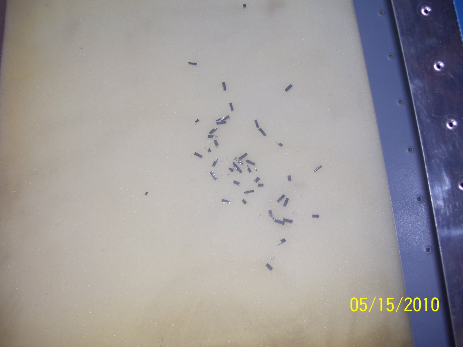
For anyone with experience in such matters, no this is not mouse poop, even though it looks like it from a distance. Believe, me, unfortunately I know what mouse poop looks like! No sign of them in the last 8 months or so, so that's a good thing. These are the remnants of the metal removed from the flange by the nibbler.


The business end of the nibbler in its non-cuttting state


Now in the cutting position. It generally will remove about 1/8 inch of material by about 1/4 inch with each cut.


The end result after nibbling and grinding the edge to a smooth edge with no burs. You can also see the marks I have made on the spar flange when trial fitting the new flange in place. That was a lot of fun by the way, because I had to use 3 hands and some tape to hold everything into place. Then I had to fit my sharpee in there to draw some reference lines and mark the hole locations in the spar web. All the trial fitting had to be done with the end rib clecoed in place. Needless to say, since I was the only one present during this delicate balancing act, I have no pics of the part taped into place during this operation.


Another shot showing the degree to which the flange was trimmed. I only cut enough to remove the bend, leaving as much of the straight part of the spar web in tact. All of the metal dust and chips from drilling/nibbling were cleaned out of the areas as well. You don't want any of this material settling into the crack and crevaces where they can start to fatigue the metal between the spar and the skin over time. Everything was spic and span before closing it all up, hopefully for the last time.

Repair of HS Tip - Hobbs 140 hours


So the repair process began. All through last week, and ending with Ron coming over to help me buck the 4 critical structural rivets for the flange repair and the re-attachment of the end rib to the HS. A series of pics of the process follows:
A bit blurry - did I ever say how much I don't like digital cameras, except that you did get instant electronic pictures I guess. This shows the top hole that was also drilled through. This entire flange had to be cut and trimmed away, and a replacement flange fabricated and riveted in its place.

Just some of the many tools used to complete this repair, and a shot of the more or less finished part that I had to cut, bend, and drill. The wood form block is the same one from earlier posts where a 1/8 inch radius bend was required. The angle finder was used to verify that the bend was exactly 84 degrees to match the angle from the forward spar to the side of the end rib where everything attaches, resulting in a 6 degree angle, or the same angle that the roots of the spars and the support angle brackets were bent to long ago. The two holes have been measured and drilled to assure proper edge distance requirements are met. Other tools used were a nibbler, my dremel grinding wheels and articulating saw attachments, metal cutting saw blades, and more.....


Another bad pic - attempting to show the angle and how the part was positioned between the two blocks during the forming process


Fitting and sizing up the side that fits up against the inside of the rib. You can see the relationship of the rib holes to the flange. These are the two remaining holes that have to be drilled. The plan is to rivet the new flange to the spar first, then fit the new end rib into place, and use the existing holes in the rib as a guide to match drill the holes into the other side of the flange.


Shows the plastic hammer I used and the form blocks and the aluminum part in the vise and being formed. Just had to eyeball this a bit and make sure that I did not force the bend over the 84 degree mark. This is actually very easy to do, and my guess-timate was very close to where it needed to be - I was only about a half degree off. You just start tapping the hammer at the base of the bend and it starts to fold right over.

Shows the part up against the angle finder - 6 degrees - with a 1/8 inch radius - just as it should be.


Now for the other difficult part of the fix - how to trim off the damaged flange from the spar. Lots of measuring involved here - not to mention trying to decide what tool/method to use to remove the flange. The trick was to remove only enough material that would not compromise edge distance on the spar web, which meant only trimming off enough material right up to where the bend occurs, without removing any material running the length of spar web, if that makes sense. Then ensuring that it is straight and free from burs, all within the confines of a skin that is already riveted in place on the spar top and bottom. Dremel cutting wheel was out of the question - too much risk of skipping and cutting into the skin, causing even more problems. Hack saw was another possible solution - but it would have to be done by hand. In the end, as shown in the pic, I chose the nibbler (man I love this tool!) I could cut small chunks out at a time, with fairly precise control over the amount of material being removed. Yup, that's my fat hand in the foreground, next to the small opening at the end of the HS.

Wednesday, May 12, 2010

Good News/Bad News

So I was able to transport my almost-complete HS up to Erie Airport past Saturday, where one of the EAA chapters I belong to, Chapter 43, was having a hangar picnic. Lots of great food and great company. There were not one, but two completed RV 10s in the hangars, and so I spent a fair amount of time gawking at them, and drueling with envy at how big and roomy this home built airplane is. I met with a tech counselor, Bill Truax, who looked over the damage to my wing skin and basically told me that it could be filled, won't ever crack, and basically told me not to worry about it, and to KPR (keep pounding rivets). That was the good news.


Now for the bad news. Later that evening, after getting the HS back home, I should have simply started closing up the rear spar and the ends and called it good. Instead, there was one rivet that attaches the end rib on the right side that did not quite get set as well as I would have liked. So I thought that I would drill out this rivet and and replace it, and then finish everything up after that. the first removal went without incident, but the attempt to reset the rivet resulted in a very badly set rivet, so I made the decision to drill it out as well, and try again. As the following picture shows, my drill slipped and I ended up drilling a new hole right through the end rib and into the spar flange that it was attached to. I then had to get creative with a pair of needle nosed pliers in order to snip away at the remaining rivet head in order to get it loose enough to remove. It did not matter, though, since the damage was already done.

A phone call to Vans yesterday, followed by a comfirming phone call to EAA HQ tech counselors today, resulted in a recommendation to:

a. Completely cut away the portion of the forward spar flange that connects to the end rib (not shown in this pic but I will add other pics as I affect this repair.)

b. fabricate a new flange part for the end of the forward spar that will need to be riveted onto the end of the web of the forward spar

c. Order a new end rib (done today), locate and final drill all the holes, debur it, dimple the holes, flute the edges, and prime it. Then finally try to rivet it in place once again.

Obviously this will set me back a bit from finishing the HS, having learned yet another very important set of lessons in the process. I'm sure this will not be the last time I have to figure out how to affect a repair like this, but, needless to say, I am very disappointed in myself right now, and in hindsight I should have left well enough alone. That said, you just have to press on when things like this happen, and realize that problems like these can still be resolved, albeit with a bit of extra effort.
The fabrication will take me some time to complete, because there are some precise measurements that have to be made for the correct size of the repalcement piece, and an 84 degree bend that needs to be made to properly line of with the web of the end rib. Lots of cutting, clamping, and drilling to do. Looks like the dimensions needed to fabricate the part are to use .032 inch thick alclad aluminum, and both sides of the piece will need to be about 1.5 inches long x 1.5 inches wide. The real dimension turns out to be about 1.65 inches x 1.39 inches in order to achieve flanges that are 3/4 of an inch wide on both sides. Bending metal is yet another specialized skill that one has to become familiar with, and it involves quite a bit of math skills and knowledge of metal properties in order to get it right. I won't bother listing out all the detailed formulas involved in figuring out the correct dimensions, except to say that I have spent most of my evening reviewing and calculating all of this. I figure this will set me back at least a week on the HS. Wish me luck I guess.