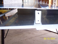
So the repair process began. All through last week, and ending with Ron coming over to help me buck the 4 critical structural rivets for the flange repair and the re-attachment of the end rib to the HS. A series of pics of the process follows:
A bit blurry - did I ever say how much I don't like digital cameras, except that you did get instant electronic pictures I guess. This shows the top hole that was also drilled through. This entire flange had to be cut and trimmed away, and a replacement flange fabricated and riveted in its place.

Just some of the many tools used to complete this repair, and a shot of the more or less finished part that I had to cut, bend, and drill. The wood form block is the same one from earlier posts where a 1/8 inch radius bend was required. The angle finder was used to verify that the bend was exactly 84 degrees to match the angle from the forward spar to the side of the end rib where everything attaches, resulting in a 6 degree angle, or the same angle that the roots of the spars and the support angle brackets were bent to long ago. The two holes have been measured and drilled to assure proper edge distance requirements are met. Other tools used were a nibbler, my dremel grinding wheels and articulating saw attachments, metal cutting saw blades, and more.....

Another bad pic - attempting to show the angle and how the part was positioned between the two blocks during the forming process

Fitting and sizing up the side that fits up against the inside of the rib. You can see the relationship of the rib holes to the flange. These are the two remaining holes that have to be drilled. The plan is to rivet the new flange to the spar first, then fit the new end rib into place, and use the existing holes in the rib as a guide to match drill the holes into the other side of the flange.

Shows the plastic hammer I used and the form blocks and the aluminum part in the vise and being formed. Just had to eyeball this a bit and make sure that I did not force the bend over the 84 degree mark. This is actually very easy to do, and my guess-timate was very close to where it needed to be - I was only about a half degree off. You just start tapping the hammer at the base of the bend and it starts to fold right over.
 Shows the part up against the angle finder - 6 degrees - with a 1/8 inch radius - just as it should be.
Now for the other difficult part of the fix - how to trim off the damaged flange from the spar. Lots of measuring involved here - not to mention trying to decide what tool/method to use to remove the flange. The trick was to remove only enough material that would not compromise edge distance on the spar web, which meant only trimming off enough material right up to where the bend occurs, without removing any material running the length of spar web, if that makes sense. Then ensuring that it is straight and free from burs, all within the confines of a skin that is already riveted in place on the spar top and bottom. Dremel cutting wheel was out of the question - too much risk of skipping and cutting into the skin, causing even more problems. Hack saw was another possible solution - but it would have to be done by hand. In the end, as shown in the pic, I chose the nibbler (man I love this tool!) I could cut small chunks out at a time, with fairly precise control over the amount of material being removed. Yup, that's my fat hand in the foreground, next to the small opening at the end of the HS.
No comments:
Post a Comment