Man where has the time gone! Been dealing with a back injury that then led to other medical problems that basically left me immobile, and then we got slammed for the past 4 days with massive non-stop monsoon rains that prevented me from venturing out into the garage except to make sure that the cars were not floating away. The sun finally came out today and I am also able to walk again,so of course it was time to get out to the factory again.
I should also mention that Airventure began this past Monday. It is bitter pill for me to swallow that I was not able to attend this year for a number of reasons, but I found some relief in the fact that EAA has done a wonderful job of providing several streaming opportunities for both video and sound for the airshows and other events during the week, so I haves pent a great deal of time online this past week taking in as much as I can. There is so much to report about all this that I will devote an entire post to it later on.
I received another order from Vans with some more ribs, more Z-brackets, and my first two tubes of Proseal. Mike Rettig has a mixing tool and the pneumatic delivery tool that I can use to dispense it so I will get with him when I am ready and borrow those items to seal the tanks.
In the mean time I have reached a point in the normal build instructions where the next step is to attach the assembled fuel tank to the wing, cinch down the tank skins to the wing spar and the adjoining LE, verify there are no gaps between the main wing skins, LE, and fuel tank, and final drill the holes for the nut plates through the fuel tank skin and the joiner plate.
This is where I deviate from the normal build process to complete the LE modification I have been planning for a very long time now. Instead, I performed the following steps:
1. Fluted, straightened, edge deburred, and filed down the Rib LE bumps to an additional 408-1 left and right rib. These ribs will replace the W709 ribs adjacent to the first 408 rib. IOW the first two inboard ribs for my LE skin will both be 408 ribs instead of the normal 408 inboard followed by W709 rib design.
2. I have struggled trying to decide between a couple of different methods for drilling the holes in the second hole-less 408 rib. My choices were basically to measure and pre-drill at least one hole in the rear flange of the rib based on measurements taken from the other 408 ribs that have already been drilled, or to position it similar to the first one and back-drill the holes through the back side of the wing spar just as I did for the other one.
After much debate with myself about how best to do this,I decided to take the measurements and attempt to drill the center hole of the rear rib flange based on those measurements, so I can alt least have a starting reference point that is attached to the wing spar while I figure out how to assemble the rest of it. Some measurements of interest for this are:
408 rib rear flange length - 4 and 7/16ths inches
Center of rear flange - 2 and 7/32 inches
Center hole location - 3/16 inches from the outer edge of the flange. I marked both this line AND the min edge distance line on the rear flange.
I marked the center hole location with a sharpee, then center punched and pilot drilled with a #40 drill bit. I was right on the money - unfortunately the wrong money with this hole. DAMMIT! I marked the min edge distance location instead of the 3/16th inch location for the center hole, so now my rear flange center hole is at max edge distance for the rib, and is 1/16 inch off from where the hole was drilled in the other 408 ribs. I basically said screw it, realizing that with the rear flange holes a bit further out from the web should create a better situation for the rib flanges centering up in the holes in the LE skin, so I went ahead and drilled the final hole to #30. If I need to I will order yet another 408 rib and do it all over again. What a pain.
I removed the existing W709 rib to be replaced with the new 408 rib while leaving the LE skin on the wing spar. I then replaced it with the 408 rib and clecoed the center hole in place. I then spent some time checking the alignment of the rib flanges by locating the reference line I drew on the flanges with the holes in the LE skin, and they seem to be OK,even after offsetting the rear flange hole by 1/16th of an inch. So I think I will continue using this rib and back drill the remaining rear flange holes once I have it squared up with the wing spar and wing skin. That will require a post of its own to describe how I do this, since the original method I described in a previous post cannot be used since this rib is inside the LE skin and is not on the outer edge. I have a plan for this that I will share in another post. I will basically remove the LE skin so that this rib is exposed so I can clamp it down against the wing spar. Having at least one hole already drilled in the rear flange of this rib makes this possible. Vans, are you paying attention?
SO why all this fuss over the rear flange of the 408 rib. Well, to put it simply, this is hard part of this entire process. It is difficult because the rear flange of this rib is notably shorter than the flange on the 409 rib, and the hole patterns in the wing spar are also different for the same reason. The only hole that aligns between the 408 and 709 ribs is the center hole. This is why the location of the center hole in the rear flange of the 408 rib is so critical. I am going to have to devise a hole pattern and possibly drill some additional holes in the wing spar web to ensure that the rear flange of the 408 rib has the proper support. I have not finalized the dimensions of this final hole pattern, but I can probably use the same pre-drilled holes to either side of the center hole, but will have to add some more holes to distribute the load on the rear flange correctly. If I use these additonal predrilled holes the hole pattern will not be the same as it is for the original 408 rib, so I have some decisions to make here.
One other thing I figured out today is the length dimension of my revised joiner plate. The original plate is 1.5 inches wide by 36.5 inches long and .032 inches thick. I realized that since my new joiner plate will be approximately 12 inches wide, I need to account for the change in the shape of the wing spar between the 2 ribs. The spar bar ends about half way in between the original 408 rib and the 709 rib that I am replacing with another 408 rib. I also realized that the final hole spacing in the LE skin is a bit different for the 709 rib location than it is for the 408 rib location.
Long story short, the length of part of my new joiner plate will need to be 36.5 inches for the first 5.75 inches of width, and then change to 36.75 inches after that in order to account for the increased LE skin hole spacing from 1 inch for the 408 rib to 1.25 inches for the 709 (and my second 408 rib). If I want the new joiner plate to connect to each of the most rearward rivet holes in the LE skin for both ribs, I will need to adjust the length of the new plate accordingly. I also need to be mindful of the clearance between the skin and the end of the tie down attach bracket for now. Truth is that much of this will get trimmed away so that only a portion remains over each rib flange similar to the original joiner plate dimensions for the rear side of the LE.
Another dimension I need to record is that the distance between rear rib flange rivet holes between the original 408 rib and the 709 rib that I am replacing is 10 inches on hole centers. The spacing between each 709 rib from that point moving outward to the outboard edge of the LE is 10.5 inches. So the spacing after this second rib is different. This is important because it basically prevents me from using the LE wing skin for one method of securing and drilling this new rib that I had been planning. Had the spacing between all the ribs been the same, I would have been able to use this method, but since this is not the case I am not even going to elaborate on how I was going to do this.
That's about it for now. Too busy measuring stuff to take pics so will try to do that tomorrow. Upcoming tasks include cutting the .032 x 12 inch wide by 42 inch long piece of aluminum to initial length measurements described above, and preparing to bend this to shape against the 408 ribs. Hopefully that will go reasonably well but will not be as easy as the smaller 1.5 inch wide strip was.
Thursday, July 31, 2014
Sunday, July 20, 2014
Z Bracket Prep Part 4 - A post of how NOT to do things
As stated in my previous post, I had messed up one hole of the 3 inboard bracket holes due to a drill press setup screw up. What I had tried to do was utilize a line that I drew on the short side of the flange to finish drilling the final holes in the part. Here is the really messed up way that I tried to do this:
 Long story short, DON'T try to drill the flanges this way. It is much more reliable, but not necessarily fool proof, to drill them from the OTHER side, or the long side. You know, the side that I previously said should not be used because it did not account for the thickness of the web of the Z bracket. SO this means that the reference line used to mark the locations of the holes should be drawn on that side of the flange and drilled from that side as well. As you can see from the pic above, I had to resort to shims and other pieces of wood to support the flange, and this just did not work very well. Flip it over and drill from the other side.
This pic shows the result with the misaligned hole on the right. The part is now scrap:
 Still waiting for my new Z brackets to arrive so I can measure, mark, and attempt to drill once again. I only ordered 7. Hopefully that will be enough! Actually I ended up taking the inboard bracket I had started for the right wing and used it for the left wing by simply turning it around 180 degrees.
And now for the next thing you should NOT do when working on the fuel tanks. During the same work session, I had been working on Z brackets and back drilling holes for several hours. I had also worked on filing down the bumps created by the relief cuts of the nose of each of the tank ribs, just as I had done for the leading edge ribs before. Now it was 11:00pm, and I decided I wanted to go ahead cleco the tank ribs to the fuel tank skin before I went to bed. I removed the vinyl from the inside of the tank skin, PLACED IT IN THE CRADLE PER DAN CHECKOWAY'S OWN RECOMMENDED PROCEDURE as well as that of several other builders, and started positioning the ribs. My thought at the time was that this was the same shape as the LE, and so I should be able to cleco them together the same way that I did with the LE ribs and skin. The only thing that was any different was that the tank ribs were shorter, and the skin was thicker.
Again, long story short, I found out that this is absolutely the WRONG thing to do. For some as yet unknown reason to me, the tank ribs do NOT conform to the LE of the tank skin very well, and because the skin is thicker it is much more difficult to try to force the ribs into the position so that the holes would line up. I started with the skins in the cradle and found that I was able to align and cleco all the holes on the top side of the skin and ribs, but getting the bottom skins to line up was next to impossible.
Knowing that the LE ribs were also stiff at first, I expected some resistance for the tanks ribs, but certainly not as much as I encountered. I started attaching the top side from the forward most hole to the rear, because I found that this most forward hole would line up with the rib the easiest. With much difficulty, I was able to push hard enough on the rear flange of the two most outboard ribs and cleco the bottom holes. Then I switched my attention to the most inboard rib, again with everything still in the cradle. While trying with ally might to push down on the rear flange of the rib with my left hand, and a cleco in my cleco pliers held in my right, I tried desparately several times to get the most forward hole to line up. When I thought I was close, I would apply pressure to the cleco with the cleco pliers while I tried to force the cleco into the holes. UNfortuantely this went bad, and I did something that I had not done in quite a while - placed two very deep and very pronounced scratches in the skin as the ends of the cleco gave out under pressure and slipped out the hole, scraping there way up the bottom side of the skin a good 6-8 inches as shown below:
 Now I am faced with having to decide if this is salvagable or not, and worry even more because this is part of a fuel tank assembly, and the last thing I want is to have leaks starting from this area as a result of this lovely example of stupidity on my part. In short, there has not been a leading ledge on this entire project that I have not managed to ding up in some way, shape, or form, so as a result they are my least favorite of all the parts of the airplane.
I said more than a few choice words at the top of my voice which I am sure woke up half the neighborhood, threw my cleco pliers on the floor in disgust, and went to bed. After taking a day or two to calm down, I assessed the damage and decided to keep moving forward. Step one was to get my ass back on VAF and do the research that I should have done in the first place to confirm all the countless others that have encountered the same problem and discover how they resolved the problem.
I found one post in particular that clearly spelled this out. Step one - take the damn tank skin out of the cradle and place it on a table or bench where you have access to move it freely back and forth from top to bottom. I put down two layers of foam padding on my work table and placed the tank skin on that.
Step 2:Every single rib must be attached at the 2 most forward rivet holes on the top and bottom of the tank skin and ribs. Once this is done you attach a few more clecoes on either side of the tank skin until each rib is in place.
By leaving the tank skin out of the cradle it does not compress the LE of the skin as much and therefore the ribs can be pushed into place much easier. Make not mistake, this was still no picnic for me. And before any others start chiming in about my rib flanges not being straight - they all were - straight as an arrow, and the flanges were all 90 degrees to the rib web. It still took some maneuvering and some pressure on each rib to get each of those first two holes to line up. Remember to start by tipping the skin up on its nose, cleco one side of the LE, and then work to line up the forward hole on the other side. Also make certain that none of the other holes have clecoes in them. I found this to work the best for me, but I tried several different methods posted by several individuals to get this to work. Each rib posed a new challenge so they all required slightly different techniques to get these holes started. If you were lucky, you ended up with this for starters:


After this you can start applying clecoes on both sides.


 The top side all done:
 And the bottom side:
 And then you are left with this rather ugly looking site. After all that work to remove the bumps from the LE of the ribs, this is what you get:
 Not a real good fit. According to other builders it is my understanding that this is normal.I guess I would expect this to be the case, since each of those separated sections is actually straight and not very curved.
I could have saved myself some aggravation and maybe even damage to my tank skin had I researched VAF. Problem is that I did not think I needed to, because even Checkoway said to use cradle. There are certain parts of this build that are anything but easy, and this is definitely one of them. Tomorrow I will post more pics of the fitting of the tank to the wing, but will end with this last pic as a sign that hopefully things are still coming together. Again, my goal is to finish the wings by the end of this year, and the fuselage by the end of next year.

This pic shows the result with the misaligned hole on the right. The part is now scrap:
And now for the next thing you should NOT do when working on the fuel tanks. During the same work session, I had been working on Z brackets and back drilling holes for several hours. I had also worked on filing down the bumps created by the relief cuts of the nose of each of the tank ribs, just as I had done for the leading edge ribs before. Now it was 11:00pm, and I decided I wanted to go ahead cleco the tank ribs to the fuel tank skin before I went to bed. I removed the vinyl from the inside of the tank skin, PLACED IT IN THE CRADLE PER DAN CHECKOWAY'S OWN RECOMMENDED PROCEDURE as well as that of several other builders, and started positioning the ribs. My thought at the time was that this was the same shape as the LE, and so I should be able to cleco them together the same way that I did with the LE ribs and skin. The only thing that was any different was that the tank ribs were shorter, and the skin was thicker.
Again, long story short, I found out that this is absolutely the WRONG thing to do. For some as yet unknown reason to me, the tank ribs do NOT conform to the LE of the tank skin very well, and because the skin is thicker it is much more difficult to try to force the ribs into the position so that the holes would line up. I started with the skins in the cradle and found that I was able to align and cleco all the holes on the top side of the skin and ribs, but getting the bottom skins to line up was next to impossible.
Knowing that the LE ribs were also stiff at first, I expected some resistance for the tanks ribs, but certainly not as much as I encountered. I started attaching the top side from the forward most hole to the rear, because I found that this most forward hole would line up with the rib the easiest. With much difficulty, I was able to push hard enough on the rear flange of the two most outboard ribs and cleco the bottom holes. Then I switched my attention to the most inboard rib, again with everything still in the cradle. While trying with ally might to push down on the rear flange of the rib with my left hand, and a cleco in my cleco pliers held in my right, I tried desparately several times to get the most forward hole to line up. When I thought I was close, I would apply pressure to the cleco with the cleco pliers while I tried to force the cleco into the holes. UNfortuantely this went bad, and I did something that I had not done in quite a while - placed two very deep and very pronounced scratches in the skin as the ends of the cleco gave out under pressure and slipped out the hole, scraping there way up the bottom side of the skin a good 6-8 inches as shown below:
I said more than a few choice words at the top of my voice which I am sure woke up half the neighborhood, threw my cleco pliers on the floor in disgust, and went to bed. After taking a day or two to calm down, I assessed the damage and decided to keep moving forward. Step one was to get my ass back on VAF and do the research that I should have done in the first place to confirm all the countless others that have encountered the same problem and discover how they resolved the problem.
I found one post in particular that clearly spelled this out. Step one - take the damn tank skin out of the cradle and place it on a table or bench where you have access to move it freely back and forth from top to bottom. I put down two layers of foam padding on my work table and placed the tank skin on that.
Step 2:Every single rib must be attached at the 2 most forward rivet holes on the top and bottom of the tank skin and ribs. Once this is done you attach a few more clecoes on either side of the tank skin until each rib is in place.
By leaving the tank skin out of the cradle it does not compress the LE of the skin as much and therefore the ribs can be pushed into place much easier. Make not mistake, this was still no picnic for me. And before any others start chiming in about my rib flanges not being straight - they all were - straight as an arrow, and the flanges were all 90 degrees to the rib web. It still took some maneuvering and some pressure on each rib to get each of those first two holes to line up. Remember to start by tipping the skin up on its nose, cleco one side of the LE, and then work to line up the forward hole on the other side. Also make certain that none of the other holes have clecoes in them. I found this to work the best for me, but I tried several different methods posted by several individuals to get this to work. Each rib posed a new challenge so they all required slightly different techniques to get these holes started. If you were lucky, you ended up with this for starters:
After this you can start applying clecoes on both sides.
I could have saved myself some aggravation and maybe even damage to my tank skin had I researched VAF. Problem is that I did not think I needed to, because even Checkoway said to use cradle. There are certain parts of this build that are anything but easy, and this is definitely one of them. Tomorrow I will post more pics of the fitting of the tank to the wing, but will end with this last pic as a sign that hopefully things are still coming together. Again, my goal is to finish the wings by the end of this year, and the fuselage by the end of next year.
Friday, July 11, 2014
Z Brackets Prep Part 3
As the next step in this process, with all the center holes drilled in the brackets, it was now time to back drill all the remaining holes. Some build logs suggest clamping the bracket down, while others say to bolt it down tight so it does not move while back drilling the two remaining holes. I decided to apply both techniques, because things have a way of moving on me whenever I try to drill accurate holes through solid material.
I knew which clamp I wanted to use, but the problem was that the clamping surface was wider than the small half inch wide flange of the Z bracket, and had a tendency to want to tip sideways when I applied the clamping force to it. So I came up with this ingenious idea of leveraging the use of one other Z bracket to essentially increase the surface area of the flange so that the clamp could sit properly. I started on the outboard end and worked my way to the inboard end of the brackets.This method of clamping worked really well, up to a point:
 I used a locking clamp for metal with the wide pads as shown in the pic. I did not want to use the one with the stub in the end as I found these to have a slight rise in the metal like a bit of slag from the forging process, and this has a tendency to leave an impression in the metal that you are clamping against. So the flat pads are better for this operation to prevent damage to the bracket flange and the spar. The other side of the clamp is on the other side of the wing spar:

 Note the clearance from the waffle plate on the back side of the wing spar - it is close so you have to be mindful of that. Also note that the clamp only reaches one side of the bracket,since the top wing skins are still attached to the other side.The goal then is to ensure that the bracket is truly square to the wing spar,then clamp in place using the procedure above, then you can back drill the hole farthest from the clamp (wing skin side):
 I used the #12 drill bit for this as shown, WITH the drill stop to avoid damaging the wing spar. You can use the reflection of the drill bit against the wing spar web to verify that the drill bit is straight. i was very worried that I might cant the bit off to one side or the other causing a warbled hole in the flange, but everything actually went very well:

 After the first hole is drilled you attach the bolt and nut assembly to that hole. This locks the bracket in place so that the clamp can now be removed and the final hole back drilled into the flange:
 This process was repeated until I got to the last bracket - the inboard one,which, as you may recall, has the holes further outboard from the web of the bracket than all the others. This is when I realized a small problem. How do I "backdrill" a hole in this flange when the nut plates are already installed. OOPS! Didn't see that one coming. Add to this the fact that this bracket resides in the area of the 4 very closely spaced ribs for the wing walk area, and you don't have much room to do anything, much less drill holes.
So here is how I resolved the problem (almost):
1. I used the nut plates rivets on the top side to draw a center line with a sharpee all the way to each side of the wing spar web. Basically I am going to extend the center lines of each hole so that I can transfer the lines to the bracket flange.
2. Admittedly I just kind of eyeballed this and had to use some odd-sized straight edges to draw the lines. One of them was the edge of a jig saw blade. It turns out that the holes are all on1.75 inch centers. I marked the lines, attached and squared up the bracket with the center bolt, and then transferred the lines to the bracket. Then I removed the bracket, verified the lines were in the correct place,and took it down to mydrill press.
 The first hole was drilled spot on as shown below:
 Then,as I mentioned at the beginning of this post, I managed to commit the ultimate sin. I went to drill the final hole of the final bracket for the left wing, and was looking forward to being able to move on to the next step of fitting and drilling the other flanges of each bracket to the baffle plate. Unfortunately, my drill pres clamping arrangement failed and the part slipped and the hole got drilled in the wrong place. This means yet another order placed with Vans. Man am I pissed. It got worse,but I'll save that for the next post.
I need to order the Proseal anyway, so its just as well. I still have to backdrill the right wing brackets, so there is still plenty to do. FYI, a new T712 bracket costs 2.50 plus shipping. I am going to order a full set of 14 more of them - just in case :)
I knew which clamp I wanted to use, but the problem was that the clamping surface was wider than the small half inch wide flange of the Z bracket, and had a tendency to want to tip sideways when I applied the clamping force to it. So I came up with this ingenious idea of leveraging the use of one other Z bracket to essentially increase the surface area of the flange so that the clamp could sit properly. I started on the outboard end and worked my way to the inboard end of the brackets.This method of clamping worked really well, up to a point:
So here is how I resolved the problem (almost):
1. I used the nut plates rivets on the top side to draw a center line with a sharpee all the way to each side of the wing spar web. Basically I am going to extend the center lines of each hole so that I can transfer the lines to the bracket flange.
2. Admittedly I just kind of eyeballed this and had to use some odd-sized straight edges to draw the lines. One of them was the edge of a jig saw blade. It turns out that the holes are all on1.75 inch centers. I marked the lines, attached and squared up the bracket with the center bolt, and then transferred the lines to the bracket. Then I removed the bracket, verified the lines were in the correct place,and took it down to mydrill press.
I need to order the Proseal anyway, so its just as well. I still have to backdrill the right wing brackets, so there is still plenty to do. FYI, a new T712 bracket costs 2.50 plus shipping. I am going to order a full set of 14 more of them - just in case :)
Wednesday, July 9, 2014
Z Brackets Prep - Part 2
After marking the adjusted center hole location for all the brackets, I setup the drill press. The next decision to make was if I should use the #12 drill bit, or a number 13 drill bit followed by a # 12 fluted reamer. I decided to go with the smaller bit and reamer combo just to try to do everything to keep from enlarging these bolt holes too much. The downside to this is that my #13 drill bit is a standard non-aviation drill bit, so the angle of the cutters is not the same, and so it does not cut as clean a hole. Anyway, pick your poison and live with it.
Setting up the drill press seems to take forever, but when done correctly the holes all end up in the right place. Here was my setup:
 And the bolt in the hole for the inboard bracket afterward:
 And here is the reamer I used, again on the cordless drill and NOT in the air drill:
 Here is how I reamed each hole after drilling it on the press:
 After drilling and reaming all the holes, I deburred them with the deburring bit, and started mounting the ones for the left wing By using an AN3-4A bolt, lock nut, and washer. I decided to mount them in the same manner that they will actually be mounted on the plane, with the bolt head and washer up against the back side of the wing spar, and the nut against the braclet flange. Others will do the reverse, but I was concerned about the clearance of the bolt head against the web of the bracket. Turns out in retrospect that either way would work fine. The nut and the bolt had have the same relative dimensions. I used a 3/8 inch nut driver and open ended wrench to tighten the middle bolts down. These need to be tight enough to prevent the bracket from moving when you back drill the remaining holes.
Beofre you can do that you need to ensure that they are perfectly square to the main wing spar web. After researching several build logs it was obvious that a small plastic or metal triangle shaped straight edge is the right tool for this job. It is small enough to fit between the spar bars bars on the top and bottom of the main wing spar. The only problem was I was sure if had one around the house or not. A check at Harbor Freight during a recent outing revealed that they do not one small enough for this job. Then I remembered that these things were pretty common school supply items. So I searched the junk drawers, and sure enough I found one that would work:
 Just line it up with spar baron one edge adn up against the edge of the bracket flange with the other. There are some tight spots where you can't lay it down perfectly flat, but you can still verify the squareness of the bracket easily. the trick was figuring how to hold the bracket square against the tool while you used two hands to tighten the bolt. I guess a clamp would have helped, but I like doing things the hard way. Here they are all setup for backdrilling the remaining holes:
 I should also mention that I ran the reamer through each of the bolt holes in the wing spar before I mounted the brackets. Here was the underside of the wing spar with the bolt in place:
 I'll wrap up this post with a blurry pic of the inboard bracket bolt screwed into the nut plate that I had installed long before attaching the main wing ribs to the spars. Atthe time I thought this was the right thing to do, and in reality it was still the right thing to do. However, I ran into a bit of a problem that I did not foresee and therefore had to resolve as a result of doing this. With the nut plates already installed, and only one of the three bolt holes marked and drilled into the inboard bracket, I could NOT backdrill the remaining 2 holes because the nut plates were already installed. So I had to figure out how to solve this problem so I could still drill the remaining two outer holes in exactly the correct position. It was a bit involved, but I managed to find a way that I will report on tomorrow.

Setting up the drill press seems to take forever, but when done correctly the holes all end up in the right place. Here was my setup:
Beofre you can do that you need to ensure that they are perfectly square to the main wing spar web. After researching several build logs it was obvious that a small plastic or metal triangle shaped straight edge is the right tool for this job. It is small enough to fit between the spar bars bars on the top and bottom of the main wing spar. The only problem was I was sure if had one around the house or not. A check at Harbor Freight during a recent outing revealed that they do not one small enough for this job. Then I remembered that these things were pretty common school supply items. So I searched the junk drawers, and sure enough I found one that would work:
Monday, July 7, 2014
Fuel Tank Prep Begins - Lots of Research, Reading, and Marking and Drilling the Z Brackets
I finished drilling the access hole for the right wing tie down ring through the right LE skin following the same procedure I outlined in detail for the left side.
Then, since I needed to wait for more parts to arrive from Vans before I could continue the work on the LE mod, I decided to start working on the Fuel Tanks. Other than reviewing the instructions in the manual from Vans, I pretty much ignored just about everything I have read about the fuel tank prep because, as many, many builders before me have already attested to, their instructions for how to do this well really suck. I have Dan Checkoway's CD and have reviewed the fuel tank section of his posts several times. I have also found several build sites with relatively good write ups and pictures, but alas, there are still little details about certain things that go missing. So I will once again try to fulfill my roll to assist other builders by providing those additional pics and details where warranted. We will start with the marking and drilling of the center bolt holes in the tank attach brackets otherwise known as Z-brackets.
They are called Z brackets because that is exactly what they are. When I started working with them I was a bit shocked at just how small and seemingly thin and flimsy they appeared to be. They are made from 1/16th inch thick extruded aluminum, so they are very thin. There are a total of 14 of them for the RV-8, so that's 7 per tank. They are shaped like the letter Z so that the flanges on either side run in opposite directions from each other.
The tank is removable for servicing, and it attaches to the wing in a number of different ways:
1. Skins attach to the main wing spar using a large number of #8 screws, all of which fit into all those nut plates that were riveted to the wing spar a long time ago.
2. The inboard leading edge of the tank attaches to a bracket that comes out of the fuselage.
3. One end of the Z bracket is bolted to the main wing spar web, while the other end is pop riveted to the baffle plate, or the rear plate of the fuel tank.
The bolt holes for the Z-brackets in the main wing spar web are pre-drilled (thank god!), but not so for each Z bracket. The challenge is to get the Z bracket bolt holes drilled in exactly the right spot so that when the tank is mounted to the LE of the wing it forms a gapless joint with the LE skins and the main wing skins. Because of their odd shape, and the fact that they are mounted between the fuel tank rear baffle and the main wing spar web, it is difficult to figure out exactly how to drill the bolt holes in each Z bracket and still end up with the skins meeting up close to each other as desired. The method for this is what Checkoway and many others have perfected and documented, and it seems to work well, so I will follow that lead.
Step 1
Measure and mark drill lines for each bolt hole.
Study the plans and make sure that you orient each bracket properly. It looks like the inboard and outboard-most brackets are oriented differently from the others. Of the 7 brackets for each tank, all but the most inboard bracket will be bolted from the back(rear) side of the main wing spar web, into nut plates mounted on one flange of the Z bracket. The inboard bracket is accessible from the front of the wing from the gap between the fuselage and the wing that is covered by the wing fairing.
So drawing the correct reference lines and marking the precise bolt hole locations on the Z bracket flanges becomes the first challenge. When you draw the drill lines for the Z brackets, do NOT mark the true center line of the flange as Vans instructs you to do. Instead you need to offset these lines so that the ones on the 6 outer brackets are about 1/16th of an inch CLOSER to the bracket web, and the holes for the inboard bracket are about 1/16th of an inch farther AWAY from the web of the bracket. The reasons you do this are:
1. Inboard bracket - allows more clearance for the thickness of a 3/8 inch socket head to be placed over the bolt head. I ran a couple of tests using two different tools to verify this. I took an AN3-4A bolt, turned it upside down, and slipped both a socket head AND a double-sided wrench over the bolt to verify how far out from the Z bracket web the bolt would need to be to allow for the wrench/socket head clearance.


 One of the above pics shows a line that I had already measured and drawn, and as you can see the bolt appears to go through that line as expected. So, lets cover some measurements, since I cannot find them listed on any builder sites or in Vans instructions. Remember that your mileage may vary, so be sure to measure your own brackets and arrive at your own measurements, and use these as a guide:
a. The length of each bracket is about 4.5 inches, making the perpendicular center point of each flange at 2.25 inches. That was the easy part.
b. Now for the longitudinal axis of the the flange. This can be tricky, so here how I did it:
- The underside (bottom) of each bracket flange from end to end includes the thickness of the center web of the bracket, which is about 1/16 of an inch thick. The width on this side was about 20/32nds of an inch, making the true center on this side to be 10/32nds of an inch.
- The side of the flange where the bracket web is located is of course about 1/16th of an inch less than the former measurement, or about 18/32nds of an inch, so the true center on this side is about 9/32nds of an inch. Both of these measurements are shown in the following pics. Disregard the poor drawing of the bolt head. I was trying to see how far away the bolt head would be from the web of the bracket of the flange of the bolt was at the farthest outer edge of the flange of the bracket. This ended up not meaning a thing, so disregard.
The first pic is the top side, or the measurement of the flange area up to the edge of the web of the bracket (18/32). This is the true amount of flange that you have to work with where either the bolt head or a nut plate must reside, and a bolt head must clear the center web of the bracket so that it can turn freely without hitting the web. The second pic is measuring from the bottom side of the flange tht includes the thickness of the center web (20/32).

 What makes this even more difficult is that there is a radius of each flange, both on the inside edge and the outside edge, so you have to do your best to try to get the "real" measurement of the flange width. So, the shorter side flange (correct) centerline would appear to be at 9/32nds of an inch, and moving it out an additional 1/16 of an inch would make it 11/32nds. After double checking my measurements, I think I went with 10/32nds of an inch, or about 1/32 inch LESS, as my drill line for the short side of the flange, because the center of the bolt head with the tool around it seemed to be closer to this measurement. This would make the measurement on the other side of the flange 12/32nds instead of 11/32nds. So this was the offset line measurement for the top and bottom of the INBOARD bracket only, NOT for any of the other remaining brackets, which require a hole CLOSER to the web, not farther away from it. Hopefully that makes sense.
Looks can be deceiving, so double check all measurements before drilling to make sure they are correct. The hole for the majority of the brackets seems way to close to the web of the bracket when you stare at it long enough. but when you realize that the only a nut plate is being attached to this flange you realize that you only need enough clearance for the bolt hole and the width of the nut plate on the short side, and you don't need the additional clearance for the bolt head because it resides on the rear side of the main wing spar web and never comes into direct contact with the Z bracket.
With the measurements for the inboard Z bracket bolt holes determined, I marked and drew the lines.
Then, since I needed to wait for more parts to arrive from Vans before I could continue the work on the LE mod, I decided to start working on the Fuel Tanks. Other than reviewing the instructions in the manual from Vans, I pretty much ignored just about everything I have read about the fuel tank prep because, as many, many builders before me have already attested to, their instructions for how to do this well really suck. I have Dan Checkoway's CD and have reviewed the fuel tank section of his posts several times. I have also found several build sites with relatively good write ups and pictures, but alas, there are still little details about certain things that go missing. So I will once again try to fulfill my roll to assist other builders by providing those additional pics and details where warranted. We will start with the marking and drilling of the center bolt holes in the tank attach brackets otherwise known as Z-brackets.
They are called Z brackets because that is exactly what they are. When I started working with them I was a bit shocked at just how small and seemingly thin and flimsy they appeared to be. They are made from 1/16th inch thick extruded aluminum, so they are very thin. There are a total of 14 of them for the RV-8, so that's 7 per tank. They are shaped like the letter Z so that the flanges on either side run in opposite directions from each other.
The tank is removable for servicing, and it attaches to the wing in a number of different ways:
1. Skins attach to the main wing spar using a large number of #8 screws, all of which fit into all those nut plates that were riveted to the wing spar a long time ago.
2. The inboard leading edge of the tank attaches to a bracket that comes out of the fuselage.
3. One end of the Z bracket is bolted to the main wing spar web, while the other end is pop riveted to the baffle plate, or the rear plate of the fuel tank.
The bolt holes for the Z-brackets in the main wing spar web are pre-drilled (thank god!), but not so for each Z bracket. The challenge is to get the Z bracket bolt holes drilled in exactly the right spot so that when the tank is mounted to the LE of the wing it forms a gapless joint with the LE skins and the main wing skins. Because of their odd shape, and the fact that they are mounted between the fuel tank rear baffle and the main wing spar web, it is difficult to figure out exactly how to drill the bolt holes in each Z bracket and still end up with the skins meeting up close to each other as desired. The method for this is what Checkoway and many others have perfected and documented, and it seems to work well, so I will follow that lead.
Step 1
Measure and mark drill lines for each bolt hole.
Study the plans and make sure that you orient each bracket properly. It looks like the inboard and outboard-most brackets are oriented differently from the others. Of the 7 brackets for each tank, all but the most inboard bracket will be bolted from the back(rear) side of the main wing spar web, into nut plates mounted on one flange of the Z bracket. The inboard bracket is accessible from the front of the wing from the gap between the fuselage and the wing that is covered by the wing fairing.
So drawing the correct reference lines and marking the precise bolt hole locations on the Z bracket flanges becomes the first challenge. When you draw the drill lines for the Z brackets, do NOT mark the true center line of the flange as Vans instructs you to do. Instead you need to offset these lines so that the ones on the 6 outer brackets are about 1/16th of an inch CLOSER to the bracket web, and the holes for the inboard bracket are about 1/16th of an inch farther AWAY from the web of the bracket. The reasons you do this are:
1. Inboard bracket - allows more clearance for the thickness of a 3/8 inch socket head to be placed over the bolt head. I ran a couple of tests using two different tools to verify this. I took an AN3-4A bolt, turned it upside down, and slipped both a socket head AND a double-sided wrench over the bolt to verify how far out from the Z bracket web the bolt would need to be to allow for the wrench/socket head clearance.
a. The length of each bracket is about 4.5 inches, making the perpendicular center point of each flange at 2.25 inches. That was the easy part.
b. Now for the longitudinal axis of the the flange. This can be tricky, so here how I did it:
- The underside (bottom) of each bracket flange from end to end includes the thickness of the center web of the bracket, which is about 1/16 of an inch thick. The width on this side was about 20/32nds of an inch, making the true center on this side to be 10/32nds of an inch.
- The side of the flange where the bracket web is located is of course about 1/16th of an inch less than the former measurement, or about 18/32nds of an inch, so the true center on this side is about 9/32nds of an inch. Both of these measurements are shown in the following pics. Disregard the poor drawing of the bolt head. I was trying to see how far away the bolt head would be from the web of the bracket of the flange of the bolt was at the farthest outer edge of the flange of the bracket. This ended up not meaning a thing, so disregard.
The first pic is the top side, or the measurement of the flange area up to the edge of the web of the bracket (18/32). This is the true amount of flange that you have to work with where either the bolt head or a nut plate must reside, and a bolt head must clear the center web of the bracket so that it can turn freely without hitting the web. The second pic is measuring from the bottom side of the flange tht includes the thickness of the center web (20/32).
Looks can be deceiving, so double check all measurements before drilling to make sure they are correct. The hole for the majority of the brackets seems way to close to the web of the bracket when you stare at it long enough. but when you realize that the only a nut plate is being attached to this flange you realize that you only need enough clearance for the bolt hole and the width of the nut plate on the short side, and you don't need the additional clearance for the bolt head because it resides on the rear side of the main wing spar web and never comes into direct contact with the Z bracket.
With the measurements for the inboard Z bracket bolt holes determined, I marked and drew the lines.
Now to continue this little math lesson, we move to the remaining 6 brackets, each of which require a bolt hole that is closer to the web. This allows a little more room for the rivet puller to be able to pull the pop rivets on the other flange of the bracket that attaches to the rear tank baffle/rear flange of each tank rib etc. Here is a pic of the line drawn for these holes.

The measurement for these holes will be 8/32nds on the bottom of the flange, and 6/32nds on the other side as shown above, again to account for the thickness of the web. When you mark that line it looks way too close to the bracket web, but in reality, it works out fine because this is just about the perfect width for the required nut plate installed on these flanges, as shown in the slightly blurry pic below:
 Once the drill lines were marked and I found the adjusted center point on each flange for the center bolt hole, I marked the point with a center punch, and then set up my drill press. I started with the left wing and right wing inboard Z brackets, since they both have the same layout and measurements. Then I reset the drill press for the remaining 12 center holes in the other 12 Z brackets for both fuel tanks and drilled them with a #13 drill bit followed by a number 12 reamer. I'll post more pics of all that tomorrow.
There is a lot more detail about this process to share....... For now, I just wanted to edit this post to include the correct measurements that I used. Again, YMMV so do your own analysis and take your own measurements. Hopefully mine will work out as planned.
The measurement for these holes will be 8/32nds on the bottom of the flange, and 6/32nds on the other side as shown above, again to account for the thickness of the web. When you mark that line it looks way too close to the bracket web, but in reality, it works out fine because this is just about the perfect width for the required nut plate installed on these flanges, as shown in the slightly blurry pic below:
There is a lot more detail about this process to share....... For now, I just wanted to edit this post to include the correct measurements that I used. Again, YMMV so do your own analysis and take your own measurements. Hopefully mine will work out as planned.
Thursday, July 3, 2014
Right Wing inboard 408 rib drilled, PartsTools ordered from Vans and Cleaveland Tools, Drilling Hole in LE for WIng Tie Down
So the short story about the ongoing saga of drilling the joiner plate and W408 ribs for the right wing is that its done for now, but not without a few more anxious moments. As a result of all the "fun" I have now wallowed out the holes in the LE skin pretty good - enough to be concerned about how the dimples will all line up in the quagmire of stupid build steps,all of which may have been resolved if they had just pre-drilled the rear flange of each 408 rib, had you pre-drill one hole in the joiner plate from which to begin that process, and instructed you to draw a line on the rib flanges.
Then, while attempting to remove my drill stop from a dull #40 drill bit, the allen screw became stripped, and I could not get it out. Tried using a stripped screw drill out tool but it did not work,and the local hardware could not find a standard or metric that allen wrench that would work. I then tried a last resort which was to take a dremel tool with the thinnest cutoff wheel that I had and try to cut a slot in the screw so I could unscrew it with a normal screw driver. This attempt failed miserably and the drill stop was all but ruined. Just for the record, when someone gives me a tool and says to make sure that the set screw is on tight to prevent things from slipping, then I make sure it is on tight. That set screw apparently was never going to come out. So my latest rant now goes to Cleaveland Tools for a bad set screw design.
I ordered 2 new ones this time, but not before I attempted to do some of the drilling on the 408 rib without the use of a drill stop. You guessed it. On a couple of holes the drill bit went right through until the tip of the drill chuck banged into the skin, causing some really nice impressions around the hole that I am not certain I will be able to dress out or not. This "HOLE" process has been nothing but a bitch for me. Here is the latest tools order received today from Cleaveland Tools:
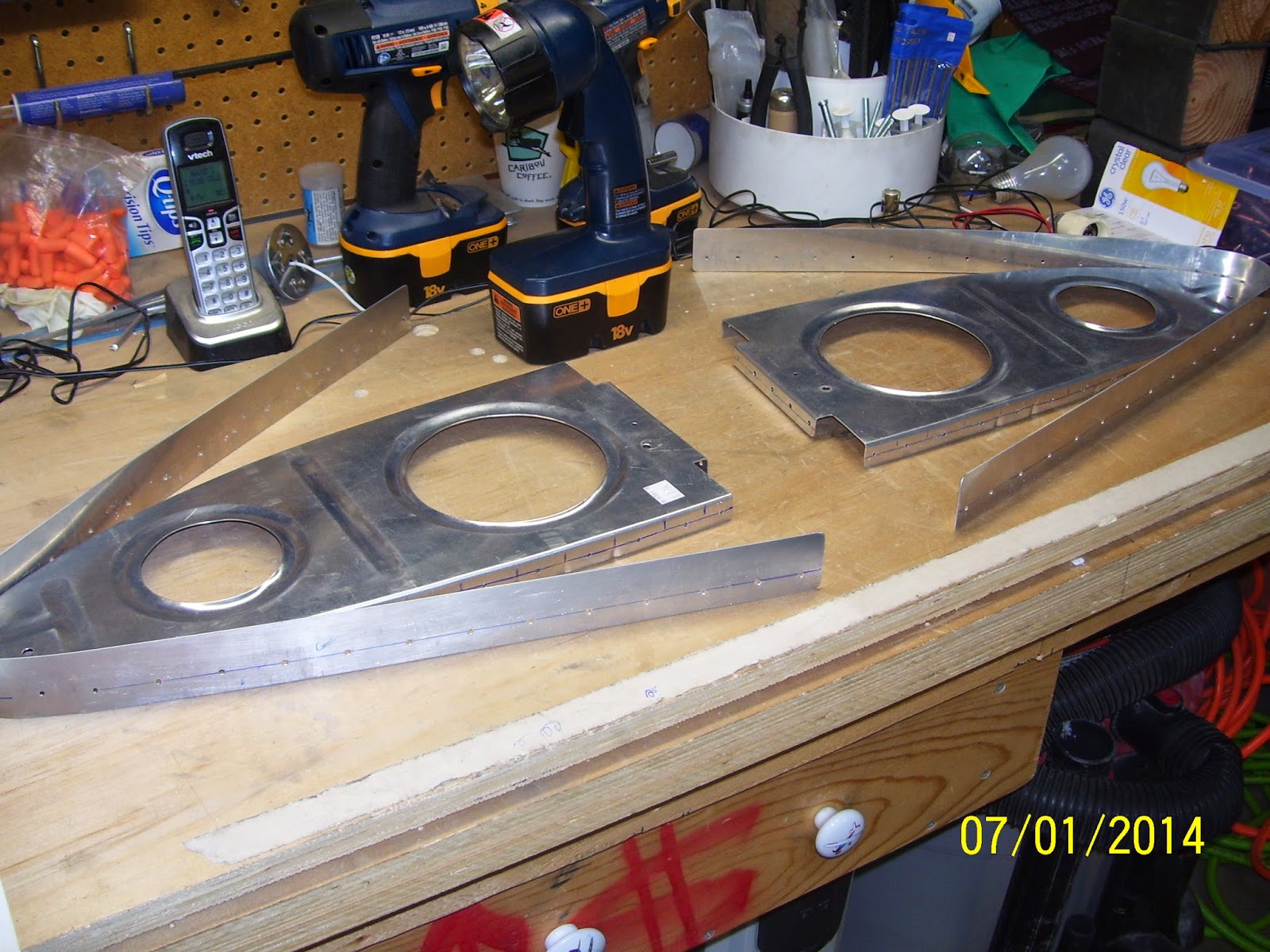
 Too bad I did not have the drill stops when I drilled out all the rib holes. Shown above are a few more scotch brite pads since rib and LE skin prep for primer is hopefully not too far off into the future. I bought a new unibit (step drill) that starts at 1/8 of an inch and has 1/32 inch graduations. I needed this to help drill out the hole in the LE skin to allow the wing tie down ring to be screwed into the bracket behind the skin. Then I bought a cutoff wheel in preparation for fuel tank ribs and other things, and a very nicely polished 3 pound bucking bar that I plan to use to back rivet the wing skins to the frame and ribs later on.
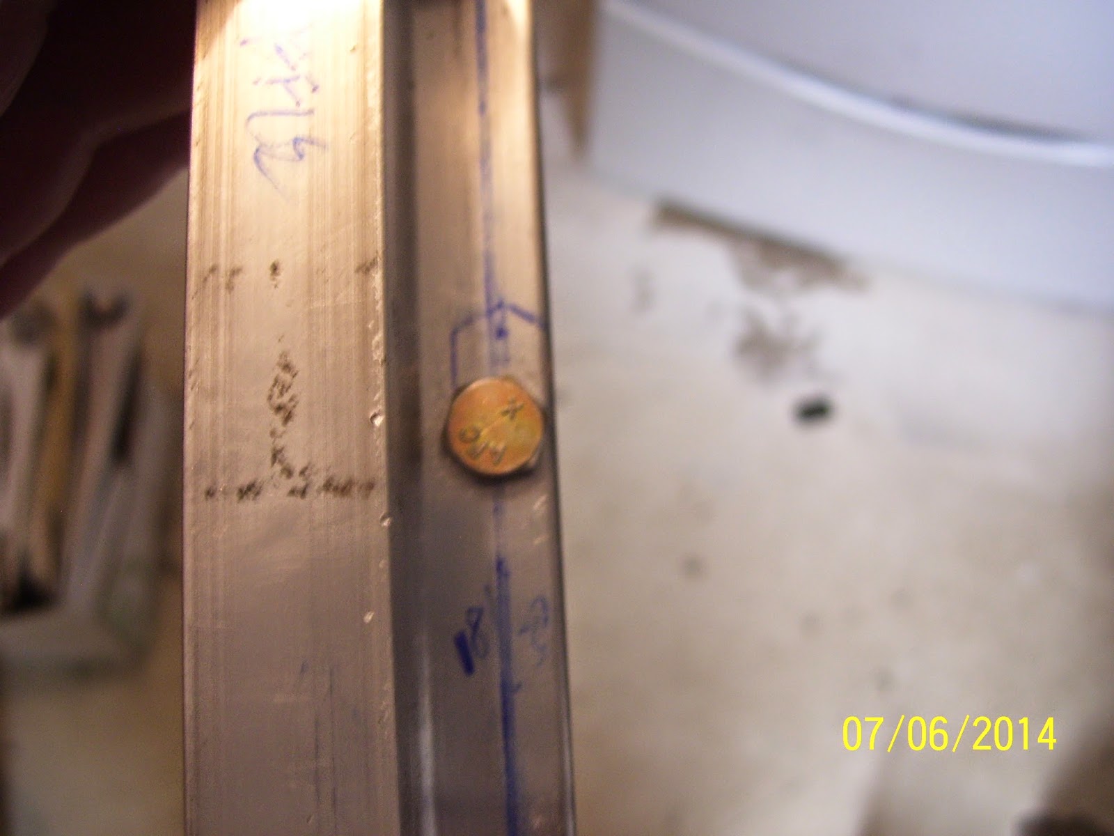
Here are some pics of the right wing 408 rib drilling exercise, following the same procedure I outlined for the left wing:

 The above holes ended up in about the same place as the left wing rib - about 1/16th of an inch above the min edge distance line shown in the pic. SO at least we have consistency here.
 All the rib flange holes ended up where I needed them (Thanks to the great airplane God!)
 I deburred most of the holes and then collasped in disbelief that I had actually completed this step. Unfortunately there is more of this to come for the mod, but I am hoping it will go much easier. Parts are on the way from Vans.
Anyway, with the holes drilled I decided to move on to the next task, and the last one that Vans states in the instructions before starting on the fuel tanks. This is the step where I have to "mark some lines on the main wing skin that will intersect with the center of the Wing Tie Down bracket hole." You know, the ones that I referenced in a previous post when I indicated that the tie down hole cannot be "referenced" by a couple of lines from the skin because directly below this hole is an inspection plate.
So I decided to do some research, and as it turns out, I think I hit a gold mine. There is a fellow in Illinois building an RV-8 that is as detail-oriented as I am. I searched online for for info about the wing tie down bracket hole and how to accurately drill it out. I found a series of pics from this builder that clarified for me how this was supposed to be done. It turns out that it is similar to a method you would use if you were flying VFR, using nothing but a paper map, and were lost. If you had a VOR on board, you would basically triangulate your position by tuning in two separate VOR stations, center the bearing needle on each one, and draw a line on your map from each VOR until the two intersect.The point of intersection is your location.
You perform a similar method to find the center point of the tie down bracket. Vans provides a starting hole for this, but also warns that variations due to builder fabrication of the bolt holes in the tie down bracket may cause deviations of the center point from this pre-drilled #40 hole. As soon as I saw the pic from this builders site I knew exactly how this needed to be done. I guess I am slower than most, because I certainly could not figure out what Vans meant in their instructions. In fact, I just read another set of instructions provided by someone in an article in the latest kit planes magazine about using piano hinges to attach your wing tips to the wings instead of using rivets or screws, and I did not like his textual description of the process either. Too many gaps and not enough detail in his instructions. More typical engineer-type behavior. They can "do it" and show you, but they sure can't write it down very well. Anyway, he provided a lot of pics so you can sort of figure it out if you think about it hard enough.
Anyway, here is the process I used for locating the center of the left wing tie down hole:
1. Cleaned up the shop since there was alot of metal debris from all that drilling
2. Since I obviously did not mark the hole location correctly, I had to remove the left wing LE from the wing, and then replace the outboard bottom wing skin temporarily. I only clecoed it enough to ensure that it was secure against the main wing spar flange, and then clecoed it in a couple of other places on each rib on either side of the tie down hole.
3. I also made a mark on the top of the tie down bracket to show the center from this position,but this is not used as the center point that you will mark on the LE skin.
 4. And now for the magic step. I used my 2 foot long ruler and a couple of clecoes placed as shown on the pic. I had my son hold one edge against the cleco on the skin, and I held the other on the perceived center line of the tie down hole in the bracket. When everything was aligned, I drew a line along the ruler on the lower skin.

 5. Then you switch over to the other cleco and do the same thing. Afterward, you end up with a cross pattern in the lower wing skin
 6. Then you re-attach the LE to the wing. I only clecoed the rear flanges of the ribs to the wing spar, and only enough clecoes for each side of the inboard section of the leading edge to ensure that it was secured enough to represent where holes should be when everything is riveted on. I did not bother clecoeing the outboard edges of the skin for this. Then you re-align the ruler so that it matches the lines you drew before, and extend those same lines onto the LE skin. IF everything works out, the lines will intersect perfectly through the middle of the #40 hole that Vans drilled. Mine ended up being a little above the center of this hole, so I had to correct for this.


7. SO how did I correct for this. I used a small round file per Vans instructions to file the hole upward just enough to allow the 1/8th inch pilot bit of my new unibit to center up in the correct location:

 8. After I filed the hole so that the center point was adjusted upward, I installed my #30 drill bit in the cordless drill (NOT my pneumatic drill).

9. Then I installed the step drill into my cordless drill - no pneumatic drills for this step. Refer to some of my previous posts about how easily this can get away from you, especially if you ar drilling into an open hole with no backing such as a drill board. I was also very concerned about being off center regardless of all this line drawing and measuring, and was very afraid that I would end up destroying the threads in my tie down bracket as a result. So the order of the day for this is to go VERY VERY slow and check the progress frequently - especially after each new step starts to bore into the metal.
I inserted the bit into the pilot hole and began slowly step drilling the hole, checking as I went. I noticed that the hole was definitely still favoring the lower part of the threaded hole for the tie down ring, so I started exerting a bit more pressure upward on the drill. What this means is that I did not file enough off the original hole and should have filed a bit more. Anyway, it looked like I could still adjust for this by applying pressure toward the top of the hole while I continued step drilling. I marked the drill bit with tape so I knew where to stop drilling. I also called Vans about this to find out how large to drill this hole, since they did not bother indicating this either in the instructions or the plans. It needs to be at least 3/8 of an inch for the ring, but I did not know how more clearance might needed or desired. Their input was to drill it out no more that 7/16th of an inch, but certainly drill it a bit more than 3/8 of an inch. My step drill bit had a step for 13/32nds of an inch,so this is the one I used.

 10. So this method worked surprisingly well, but it was not entirely fool proof. There are plenty of opportunities to mess this up, so taking it slow of the best advice I have to offer. Use a non-pneumatic drill and go slowly. check and adjust as necessary. Keep the step drill straight as it penetrates the skin. The step drill cleared all the threads in the bracket, so I was happy about that. And the final check, of course, was to verify that the tie down ring can be inserted into the bracket through the new hole in the skin:
 11. Wash, rinse, and repeat for the right wing.
Then, while attempting to remove my drill stop from a dull #40 drill bit, the allen screw became stripped, and I could not get it out. Tried using a stripped screw drill out tool but it did not work,and the local hardware could not find a standard or metric that allen wrench that would work. I then tried a last resort which was to take a dremel tool with the thinnest cutoff wheel that I had and try to cut a slot in the screw so I could unscrew it with a normal screw driver. This attempt failed miserably and the drill stop was all but ruined. Just for the record, when someone gives me a tool and says to make sure that the set screw is on tight to prevent things from slipping, then I make sure it is on tight. That set screw apparently was never going to come out. So my latest rant now goes to Cleaveland Tools for a bad set screw design.
I ordered 2 new ones this time, but not before I attempted to do some of the drilling on the 408 rib without the use of a drill stop. You guessed it. On a couple of holes the drill bit went right through until the tip of the drill chuck banged into the skin, causing some really nice impressions around the hole that I am not certain I will be able to dress out or not. This "HOLE" process has been nothing but a bitch for me. Here is the latest tools order received today from Cleaveland Tools:
Here are some pics of the right wing 408 rib drilling exercise, following the same procedure I outlined for the left wing:
Anyway, with the holes drilled I decided to move on to the next task, and the last one that Vans states in the instructions before starting on the fuel tanks. This is the step where I have to "mark some lines on the main wing skin that will intersect with the center of the Wing Tie Down bracket hole." You know, the ones that I referenced in a previous post when I indicated that the tie down hole cannot be "referenced" by a couple of lines from the skin because directly below this hole is an inspection plate.
So I decided to do some research, and as it turns out, I think I hit a gold mine. There is a fellow in Illinois building an RV-8 that is as detail-oriented as I am. I searched online for for info about the wing tie down bracket hole and how to accurately drill it out. I found a series of pics from this builder that clarified for me how this was supposed to be done. It turns out that it is similar to a method you would use if you were flying VFR, using nothing but a paper map, and were lost. If you had a VOR on board, you would basically triangulate your position by tuning in two separate VOR stations, center the bearing needle on each one, and draw a line on your map from each VOR until the two intersect.The point of intersection is your location.
You perform a similar method to find the center point of the tie down bracket. Vans provides a starting hole for this, but also warns that variations due to builder fabrication of the bolt holes in the tie down bracket may cause deviations of the center point from this pre-drilled #40 hole. As soon as I saw the pic from this builders site I knew exactly how this needed to be done. I guess I am slower than most, because I certainly could not figure out what Vans meant in their instructions. In fact, I just read another set of instructions provided by someone in an article in the latest kit planes magazine about using piano hinges to attach your wing tips to the wings instead of using rivets or screws, and I did not like his textual description of the process either. Too many gaps and not enough detail in his instructions. More typical engineer-type behavior. They can "do it" and show you, but they sure can't write it down very well. Anyway, he provided a lot of pics so you can sort of figure it out if you think about it hard enough.
Anyway, here is the process I used for locating the center of the left wing tie down hole:
1. Cleaned up the shop since there was alot of metal debris from all that drilling
2. Since I obviously did not mark the hole location correctly, I had to remove the left wing LE from the wing, and then replace the outboard bottom wing skin temporarily. I only clecoed it enough to ensure that it was secure against the main wing spar flange, and then clecoed it in a couple of other places on each rib on either side of the tie down hole.
3. I also made a mark on the top of the tie down bracket to show the center from this position,but this is not used as the center point that you will mark on the LE skin.
7. SO how did I correct for this. I used a small round file per Vans instructions to file the hole upward just enough to allow the 1/8th inch pilot bit of my new unibit to center up in the correct location:
9. Then I installed the step drill into my cordless drill - no pneumatic drills for this step. Refer to some of my previous posts about how easily this can get away from you, especially if you ar drilling into an open hole with no backing such as a drill board. I was also very concerned about being off center regardless of all this line drawing and measuring, and was very afraid that I would end up destroying the threads in my tie down bracket as a result. So the order of the day for this is to go VERY VERY slow and check the progress frequently - especially after each new step starts to bore into the metal.
I inserted the bit into the pilot hole and began slowly step drilling the hole, checking as I went. I noticed that the hole was definitely still favoring the lower part of the threaded hole for the tie down ring, so I started exerting a bit more pressure upward on the drill. What this means is that I did not file enough off the original hole and should have filed a bit more. Anyway, it looked like I could still adjust for this by applying pressure toward the top of the hole while I continued step drilling. I marked the drill bit with tape so I knew where to stop drilling. I also called Vans about this to find out how large to drill this hole, since they did not bother indicating this either in the instructions or the plans. It needs to be at least 3/8 of an inch for the ring, but I did not know how more clearance might needed or desired. Their input was to drill it out no more that 7/16th of an inch, but certainly drill it a bit more than 3/8 of an inch. My step drill bit had a step for 13/32nds of an inch,so this is the one I used.
Subscribe to:
Posts (Atom)