Then, while attempting to remove my drill stop from a dull #40 drill bit, the allen screw became stripped, and I could not get it out. Tried using a stripped screw drill out tool but it did not work,and the local hardware could not find a standard or metric that allen wrench that would work. I then tried a last resort which was to take a dremel tool with the thinnest cutoff wheel that I had and try to cut a slot in the screw so I could unscrew it with a normal screw driver. This attempt failed miserably and the drill stop was all but ruined. Just for the record, when someone gives me a tool and says to make sure that the set screw is on tight to prevent things from slipping, then I make sure it is on tight. That set screw apparently was never going to come out. So my latest rant now goes to Cleaveland Tools for a bad set screw design.
I ordered 2 new ones this time, but not before I attempted to do some of the drilling on the 408 rib without the use of a drill stop. You guessed it. On a couple of holes the drill bit went right through until the tip of the drill chuck banged into the skin, causing some really nice impressions around the hole that I am not certain I will be able to dress out or not. This "HOLE" process has been nothing but a bitch for me. Here is the latest tools order received today from Cleaveland Tools:

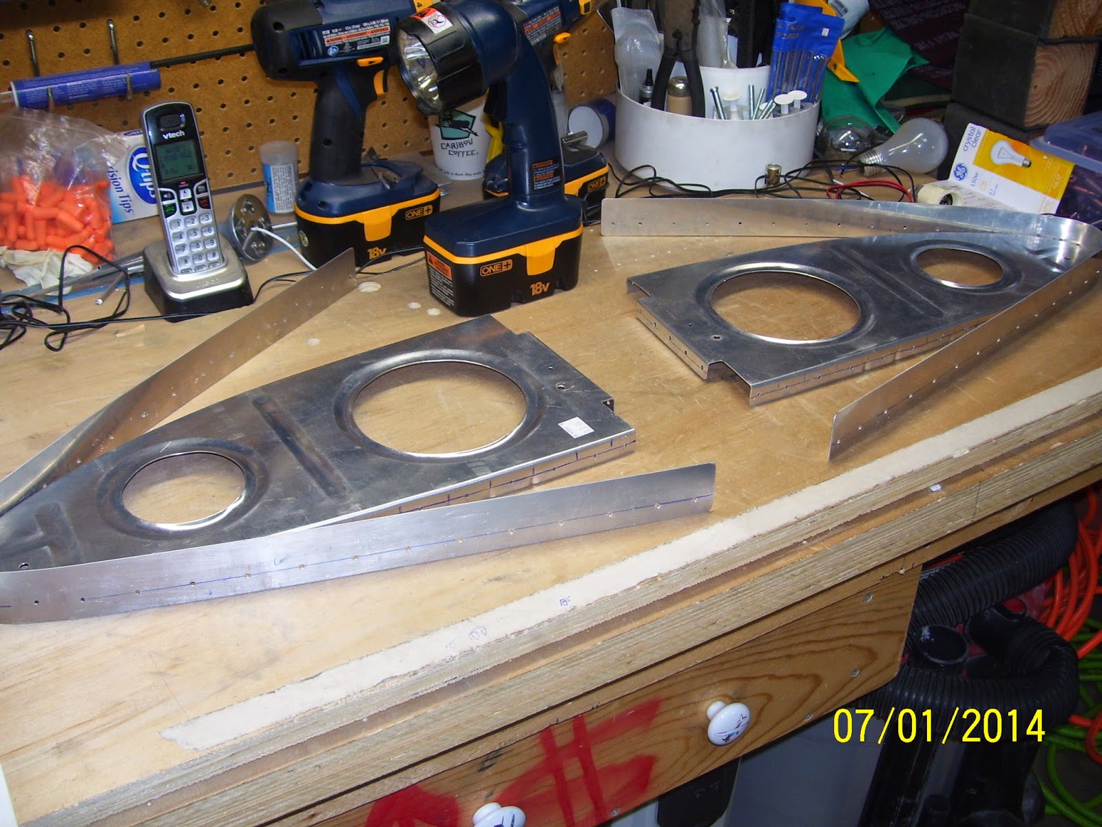
Here are some pics of the right wing 408 rib drilling exercise, following the same procedure I outlined for the left wing:


Anyway, with the holes drilled I decided to move on to the next task, and the last one that Vans states in the instructions before starting on the fuel tanks. This is the step where I have to "mark some lines on the main wing skin that will intersect with the center of the Wing Tie Down bracket hole." You know, the ones that I referenced in a previous post when I indicated that the tie down hole cannot be "referenced" by a couple of lines from the skin because directly below this hole is an inspection plate.
So I decided to do some research, and as it turns out, I think I hit a gold mine. There is a fellow in Illinois building an RV-8 that is as detail-oriented as I am. I searched online for for info about the wing tie down bracket hole and how to accurately drill it out. I found a series of pics from this builder that clarified for me how this was supposed to be done. It turns out that it is similar to a method you would use if you were flying VFR, using nothing but a paper map, and were lost. If you had a VOR on board, you would basically triangulate your position by tuning in two separate VOR stations, center the bearing needle on each one, and draw a line on your map from each VOR until the two intersect.The point of intersection is your location.
You perform a similar method to find the center point of the tie down bracket. Vans provides a starting hole for this, but also warns that variations due to builder fabrication of the bolt holes in the tie down bracket may cause deviations of the center point from this pre-drilled #40 hole. As soon as I saw the pic from this builders site I knew exactly how this needed to be done. I guess I am slower than most, because I certainly could not figure out what Vans meant in their instructions. In fact, I just read another set of instructions provided by someone in an article in the latest kit planes magazine about using piano hinges to attach your wing tips to the wings instead of using rivets or screws, and I did not like his textual description of the process either. Too many gaps and not enough detail in his instructions. More typical engineer-type behavior. They can "do it" and show you, but they sure can't write it down very well. Anyway, he provided a lot of pics so you can sort of figure it out if you think about it hard enough.
Anyway, here is the process I used for locating the center of the left wing tie down hole:
1. Cleaned up the shop since there was alot of metal debris from all that drilling
2. Since I obviously did not mark the hole location correctly, I had to remove the left wing LE from the wing, and then replace the outboard bottom wing skin temporarily. I only clecoed it enough to ensure that it was secure against the main wing spar flange, and then clecoed it in a couple of other places on each rib on either side of the tie down hole.
3. I also made a mark on the top of the tie down bracket to show the center from this position,but this is not used as the center point that you will mark on the LE skin.


7. SO how did I correct for this. I used a small round file per Vans instructions to file the hole upward just enough to allow the 1/8th inch pilot bit of my new unibit to center up in the correct location:


9. Then I installed the step drill into my cordless drill - no pneumatic drills for this step. Refer to some of my previous posts about how easily this can get away from you, especially if you ar drilling into an open hole with no backing such as a drill board. I was also very concerned about being off center regardless of all this line drawing and measuring, and was very afraid that I would end up destroying the threads in my tie down bracket as a result. So the order of the day for this is to go VERY VERY slow and check the progress frequently - especially after each new step starts to bore into the metal.
I inserted the bit into the pilot hole and began slowly step drilling the hole, checking as I went. I noticed that the hole was definitely still favoring the lower part of the threaded hole for the tie down ring, so I started exerting a bit more pressure upward on the drill. What this means is that I did not file enough off the original hole and should have filed a bit more. Anyway, it looked like I could still adjust for this by applying pressure toward the top of the hole while I continued step drilling. I marked the drill bit with tape so I knew where to stop drilling. I also called Vans about this to find out how large to drill this hole, since they did not bother indicating this either in the instructions or the plans. It needs to be at least 3/8 of an inch for the ring, but I did not know how more clearance might needed or desired. Their input was to drill it out no more that 7/16th of an inch, but certainly drill it a bit more than 3/8 of an inch. My step drill bit had a step for 13/32nds of an inch,so this is the one I used.


No comments:
Post a Comment