So I seem to have some trouble adjusting the depth of my rivet sets in my hand squeezer. After setting the majority of of the top and bottom side rivets on the left elevator, I went back with my depth gage to check the rivets, and every one of them was set just a tad shy of where I normally like them. I have met some builders who state that the shop head of the rivet is supposed to sit just inside the hole, without any play, in order to determine if the shup head has been set correctly. Then I ahve attended classes, watched videos, adn read instructions for tools that state that the rivet head should never fit inside the hole, and this is the appraoch that I have always taken.
I am certain this will qualify as one of those never ending debate topics on VAF forums. IN any event, I needed to readjust the depth of my rivet sets and go back and squeeze each rivet again just a bit more to get them to ook the way I wanted. The problem arose from trying to check rivets on the top sides of the spars and ribs after squeezing them. My crummy progressive lense glasses end up giving me the perception that the rivets are set correctly as I check them with the gage, but when I flip the part over and check those same rivets that are now face up on the bottom (easier to see the gage sitting on the rivet), I see that all the shop heads are sliding inside the rivet hole of the gage.
Anyway, after getting that resolved, it was time to turn my attention to the trim tab. What an operation that turns out to be. This is yet another exercise of determining the correct positioning, clamping, tool selection, and technique to accomplish the job. I tried to take some pics that you don't normally see on most builders logs to help dispell some of the mystery behind how this works. So here we go....
First is my clamping setup. You supposed to rivet the trim tab spar to the bottom of the trim tab skin first. The spar is Z shaped, and requires either a flange yoke or a long extension back rivet set to accomplish this correctly. I chose to use the flange yoke technique. TO start, you need to clamp the bottom skin down flat on your bench. I used two small hobby sized bar clamps that were able to fit inside the ends of the trim tab skin, and also helped lift the top skin up just a bit, which you will need to do to fit the flange yoke inside to set the rivets. Note how the skin is raised up off of the top of the spar on the outboard end of the trim tab.


If I had it to do over again I would have cut some wood to form a wedge, which would work a bit better than square blocks of wood like I used, but they still did the job. Next was deciding which rivet sets to use, and which way to install them in the yoke. I went through several girations of this, until I finally figured out what I needed as shown in the next pic:

SO I ended up using the 1/8 inch thick x 1/2 inch wide flat set on the bottom, or in the above pic it's on the left, and the 3/8 inch wide x 1/2 inch long flat set on the top of the yoke, or in the pic it is on the right. This allowed me to ensure that I had enough of the flat set on the bottom covering the flush head of the rivet, and the longer set on the top allowed me to reach behind the trim tab front spar and squeeze the rivet shaft down to the proper depth. It worked very well.
Next was trying to determine how I was going to keep the rivets in place, since they would need to be inserted from the bottom, based on the way that I ahve clamped everything to the bench. My first decision was to use back rivet tape to hold them into place. Seemed like a good idea, but the tape was not working out very well for me. This was most likely because I was still trying to figure out how to best position the squeezer, and during that time on the first rivet I messed up the tape, which caused the rivet to slip out.
So I decided to try another solution for this which up until now I had never really done before. I decided to pre-squeeze, or swell the rivets just a bot before inserting them into the rivet holes, to force them to stay in place once they were inserted. I had read about this technique, but had not had an opportunity to try it. First time for everything......
The process involves taking a rivet and inserting in between the two rivet sets in the squeezer, as show in the next pic. The tricky part is quezzing it down just far enough to allow it to still insert inato the hole, but tight enough to where it will remain in place and will not fall down or out of the hole. It does not take much to do this, and finding the right pressure to apply on the squeezer can be a bit of a challenge. After a couple of attempts I pretty much had it down to rough science:

The next pic probably does the best job of showing how the squeezer needs to be positioned for this task. Yup another FAA shot to prove that I am the insane idiot that is actually building this thing, even it if it is only showing the bald spot on the top of my head. Yikes!

1. Started with rivet inserted into one hole, clecoes in all other bottom holes, working from the outboard or small end of the trim tab toward the inboard or root/large end. Why in that sequence? Because I wanted to tackle the hard holes first. The outboard holes are harder to rivet because the skin is much harder to left out of the way at the smaller end. Start with the sets slightly farther apart than needed so that you can determine the proper depth to set the rivets.
2. Lift the top skin up far enough to be able to see the shaft of the yoke as you slide it behind the spar web adn over the rivet shaft.
3. Slide the yoke into poistion over the rivet from the end, and gently apply pressure to the handles of the squeezer and watch the top head come down over the shaft of the rivet. Move the squeezer as needed so that the rivet shaft is centered as much as possible over the rivet shaft.
4. With the squeezer into position on the top, bend down and focus your attention on the bottom set which is over the flush head of the rivet and the bottom trim tab skin. Make certain that this rivet set is sitting flat over the skin and on the rivet head, and then squeeze a way. I found that I needed to use my left hand initially to hold the top skin back so that I could slide the squeezer into position with my right hand. Once I had enough pressure to just hold the top set in place over the rivet shaft, I could let go of the top trim tab skin, and use both hands to squeeze the rivet. This also helped ensure that the bottom set remained flat on the rivet head and the skin. This is the step you see me performing in the above pic.
5. Once the rivet is squeezed, take your left hand and hold the top skin up again so that you can remove the squeezer the same way it was inserted out the end of the trim tab.
6. Check the rivet t ensure it is set correctly. If not, adjust the depth of the sets and squeeze it again if necessary.
7. Remove the cleco for the very next hole, and start the process all over again.
Note that the squeezer handles are facing down, and not up. Took me a while to figure out that this is the way I needed to position it to squeeze these rivets.
First rivet is set successfully - YAY!


This next pic turned out blurry, but I am trying to show that when you get down to the last three rivets on the bottom, pay very close attention so you don't mess this up. You can set the very last rivet with the squeezer, but DO NOT set the next two rivets until the you have the E717 and E718 trim tab control horn brackets in position on the bottom of the trim tab. These holes will also require at least a 3-4 rivet instead of the 3-3.5 rivets used on the other holes. Since I am using riblets in the ends I also needed to wait until those are installed before I set bottom rivets number two and three from the root of the trim tab. I cannot install those permanently until the trim tab is final fitted into position on the elevator.

A nice line of rivets shown here - every one of them set successfully:

Next are a few pre-squeezed rivets that I ended up over squeezing just a bit. They would not fit into the holes, even after using my large mushroom flush set to try to push the rivet through the hole. So I used some pliers to grab the head of the rivet and pull it back out of the holes, and got a different rivet and tried again.


Next is a little issue that I noted while browsing through Steve Riffe's builders log. The trim tab control horns attach to the bottom of the trim tab skin at the root. to try to prevent corrosion, the surface of the trim tab skin that mates to the two control horn halves should be primed or otherwise treated. I guess there have been reports that this is one of the areas for water to collect and where corrosion is most often found. So I tool the time to prime the surface of the skin where it contacts the parts for the control horn. Here I ahve masked it off for priming:


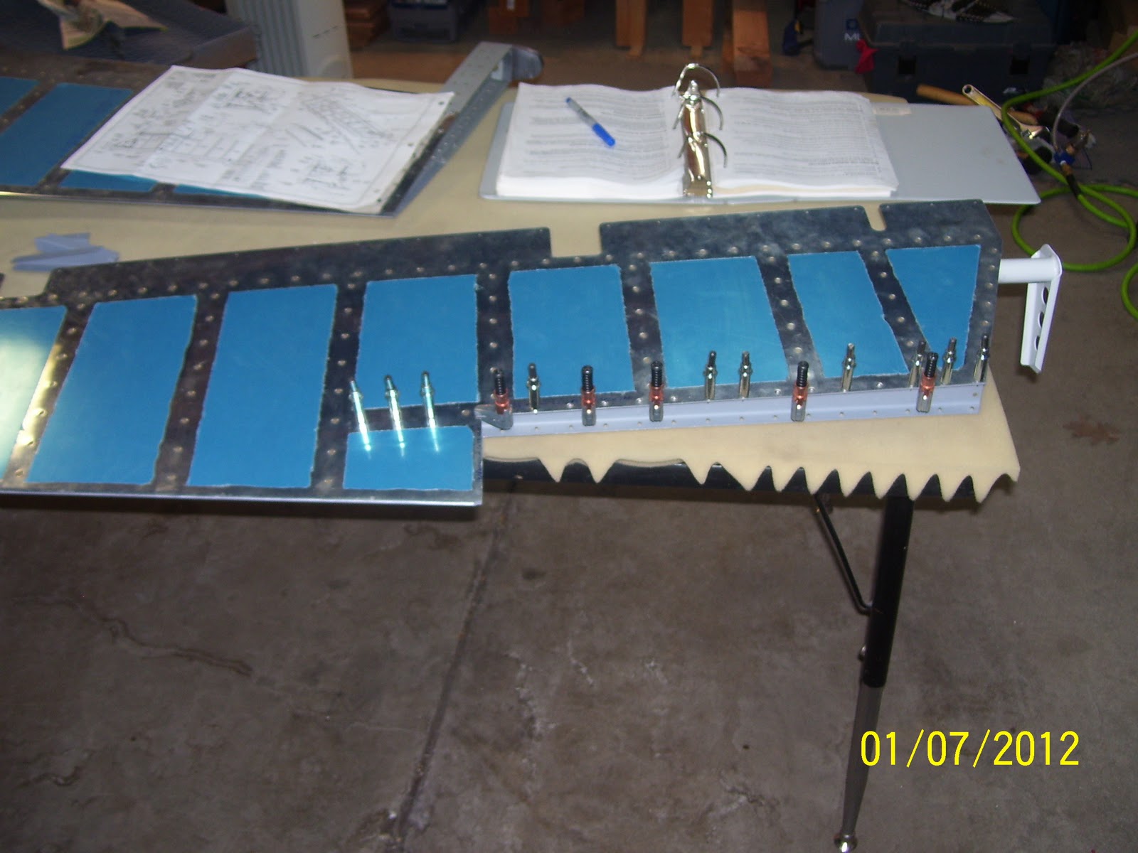
Lastly are some shots of the top side of the elevator after getting those rivets set. The clamps you see are holding the top of rear spar to the skin in preparation for the next step, which is to fit the other half of the trim tab hinge adn final fit the trim tab assembly to the elevator. After that is done, only the trim tab servo remains. Then I get to haul the horizontal stab down off the wall to assemble and trial fit the elevators - -I can hardly wait!!!!


No comments:
Post a Comment