This joining together of major airframe parts is something that has always fascinated me. Being a WW II aviation history buff, I am always intrigued when I see film footage of the factories that were creating fighters and bombers in an assembly line. Large overhead cranes and straps with fuselages and wings suspended from them would somehow be guided into place by a handful of humans, and then they would be magically joined together. I guess this fascinates me even more right now, after having been exposed to airplane building techniques, many of which were developed and perfected way back during WW II.
Three of us - Mike, myself, and Jon Banks were all that were needed to complete this tasks. The process we used at Mike's did not require any cranes or heavy weight-bearing straps, but was still just as challenging and fascinating to see it all happen. Mike's tailcone was strapped down on a 4-wheeled flat dolly shown below:

Before we began the joining process the forward section was up on several saw horses. Mike had Built two very interesting dollies for the forward section. They basically looked like two miniaturized sets of landing gear bolted to the center section wing spar flanges. Jon and I both made fun of these rather interesting sets of wheels, but turns out that they more-than served their intended purpose. The first step was to get the forward section off of the saw horses and onto the ground.


The rear of the forward section was temporarily sitting on the two steps that will be utilized by pilot and passenger to enter the cabin of the airplane. I am dubbing the above pic the "midget 10." With that done, the next step was to maneuver both sections and begin the process of aligning them at the proper angles so they could be joined together and secured.
The trick to this turned out to be setting both sections at the proper angle so that all the mating surfaces of both sections would line up correctly. How was done, you might ask? Measuring sophisticated complex angles, or lifting both sections a prescribed amount? Well, it turns out that several pieces of 2 inch thick foam under the rear section, and some boxes full of books were used on the front section to get both pieces at approximately the right angle so they could be joined together.
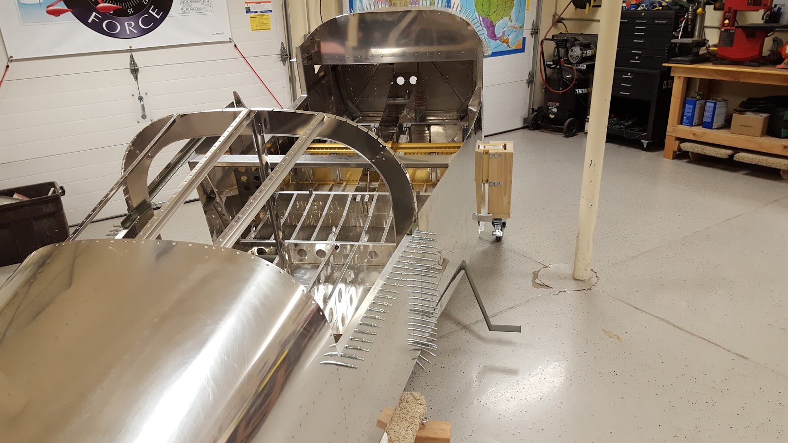
This task was not easily done in one shot. It took several attempts at adjusting the foam and the boxes either forward or back from their current positions, and then eyeballing the angles and alignment of the mating surfaces of both parts. Then the metal had to be aligned and positioned correctly while the front section was locked into place and the tail was maneuvered forward and from side to side. It was further complicated by the fact that there were several different types of metal to join, and some of it needed to be sandwiched in between metal from the other part, while flanges from the bulkhead and various pieces of aluminum angle all had to be aligned as well. this took several attempts to get right. When we began, the left side aluminum was lining up, but the right side was not. Then one part would go in correctly and another would pop back out..... After messing with this for about 20 minutes, it all finally came together.
Then the task of inserting clecoes into the joined parts began. Getting ALL the rivet holes to line up enough to insert the clecoes was also a challenge for certain areas. Here is Mike with pliers in hand making it happen:

And here is Mike and Jon after the deed was accomplished. This is yet another major milestone in completing the airplane, so smiles are more than appropriate:

Not so easy to move things around anymore, is it?

Here is a pic that shows the final locations of the rear dolly, which has been moved up about halfway to serve as a support for a box that sits under the major support section of the bottom of the forward section and the location of the box being used to support the tail section. The combination of the rear dolly and the wheels mounted on the forward section gives just enough clearance to keep the foot steps off the ground and keeps both sections pretty well lined up.

And finally - Mike at the pilot's position with a makeshift seat in forward section of the cabin. I'm really jealous of this and I can hardly wait until that is me in my fuselage skeleton making airplane noises - a right of passage for builders that reach this important stage of the build.

Then, after all the hard work was done, Mike treated Jon and I to dinner. Thanks for that Mike! Now I can add this to my list of engine hanging and wing joining exercises I have been fortunate to be a part of. Not shown in these pics is the very large top fiberglass section that also joins the two halves together on the upper portion of the fuselage. I imagine Mike will be starting on that work in the not-too-distant future. Lookin' good Mike!
No comments:
Post a Comment