First I have to rant - this post falls under my Vans sucks category so be prepared. After drilling all the holes in the joiner plate and 408 rib and the LE skin, I decided to remove the assemblies to see how well my holes turned out. I should have done more homework, because I think I hit upon one of the next great blunders in Van's building instructions that are just plain wrong, insufficient, etc. The joiner plates came out mostly OK. The ribs on the other hand are now scrap. The holes on the bottom flange all turned out OK, but the ones on the top, as I came to better understand after researching this a bit more, tend to wander inward as you drill, and therefore the rib flange holes turn out to be much too close to the rib web. There is a problem with the hole being too close to the rib web. Vans has stated that this can weaken the radius where the flange was bent and thus having holes too close to the web is not desired either.The other obvious problem is that you may never be able to get a good dimple for the holes. Here is pic that unfortunately demonstrates the demise of both the left wing and right wing 408 ribs:

Or so I thought anyway, until I stumbled upon several posts by fellow builders on VAF, the main one being this one:
Correct way to attach and drill 408 ribs and 423 joiner
I ended up using a combination of things from this post to address the problem and ensure a much more favorable outcome - no thanks to Vans - who should have done a much better job of explaining how to do this. This is yet another one of those coveted Vans blunders that forces you to have to order a new part-in this case new W408 ribs.
Step 1
So I have to order new 408 ribs, and if your joiner plate did not come out right then you need to order or fabricate new ones as well. I had already ordered two new 408 ribs so I just happened to have them on hand. I still need to order two more at 23 bucks a pop for my LE mod.
Step 2
Make certain that you mark the flute locations and flute the rib so that it is perfectly straight (or as straight as you can make it, since I have come to realize that NOTHING about metal airplane parts is perfectly straight - especially ribs)
Step 3
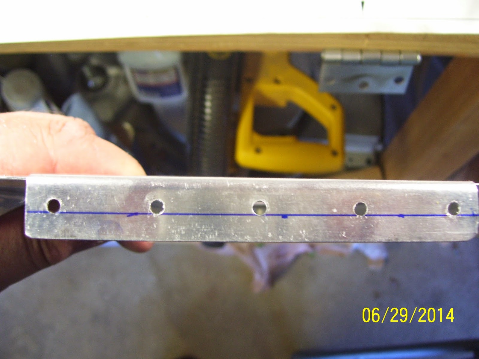
I decided to mark the minimum edge distance of the rear rib flange instead of trying to find the center line. Min edge distance for 1/8 inch rivets is 1/4 inch for the AN470AD4 rivets that are used to attach the ribs to the wing spar. Here is the line and the method I used to draw it. This edge distance was taken from the outer edge of the flange, and not from the rib web. I did it this way because I wanted to know where the maximum outer location of each rib could be. The center of each rivet cannot be any closer than a quarter inch from the outer edge of the flange.


Next, use the following tools to securely fasten the rear of the rib to the wing spar
- A Large square
- 3 bar clamps - one larger one to clamp the square to the wing spar, and the other two smaller ones to secure the rear flange of the rib to the wing spar. Clamp everything in place, being sure that the rear rib flange is flat against the wing spar web. The edge of the square is placed right up against both sides of the wing skin and along the edge of the wing spar flange, so make sure the edges of the wing skin are clecoed in all holes in this area.


STEP 5
Start drilling the holes for the rear rib flange from underneath the wing spar web. Drill one hole and cleco, and check the rib flange to see if the location of the holes looks OK. The goal here is to drill all these holes in a straight line, which I sadly found not to be the case on my original right wing rib.


When done drilling all 5 holes, remove the rib and joiner,etc and inspect the location of the holes in the rear flange. They should be straight, and as the next pic shows they will also NOT align with the min edge distance line that was drawn earlier. I should note that I checked for this line through the holes before I started drilling with a mirror, and I could not see the marks then, which simply told me that the holes will be located somewhere other than at min edge distance. Here is where they actually ended up:
Step 7
Now a reference line needs to be drawn on both the top and bottom rib flanges. The plan for all this is to re-use the drilled joiner plate since those holes are in position already, and use the line drawn on the rib flanges to align the rib through the existing holes in both the skin and the joiner plate. If you are drilling the joiner plate for the first time, then you should assemble all the parts thee best you can, trying to maintain that idiotic 11/16 inch extension of the plate from both the skin and the rib web. Then pre-drill the plate through the wing skin without drilling all the way through the rib. Then remove the joiner plate that you just spent all that time aligning, and finish drilling out the holes on a drill board. Actually, the nice thing about this is that you don't have to try to maintain the 11/16 inch extension. Instead, you should simply focus your attention on the ensuring that the holes in the joiner plate align with the line that was drawn per the plans. Center the line through the wing skin hole and then predrill each hole in the plate. At this point I don' t think it matters much if you do a few holes on one side and then a few on the other. If the half inch line was drawn correctly all you need to do is focus on the line through the wing skin hole.
Once you have final drilled the holes in the joiner plate, remove the rib as described above, and draw a reference line on the rib flanges that will show through both the skin holes and the joiner plate holes. To draw the reference line, you simply use a technique that I learned on Hints for home builders about fabricating a wing rib from scratch. You use your fingers and a set position of the sharpee pen in the desired location of the rib flange (usually the centerline of the flange as best you can eyeball it.) I used the same technique when I drew the line for the forward spar of the horizontal stabilizer. As you can see from the pic it worked pretty well, but the flutes got in the way and distorted it in a few areas. I must have redone this line about 8 times before I was satisfied with it. I used acetone to remove the line and start over. Always run the line from the bent side of the flange,and never the open end, since that side may have slightly varying dimensions due to the hydro-forming process- especially when dealing with formed ribs.

STEP 8
With the rib flange lines drawn, insert the rib under the joiner plate and skin. Cleco the rear flange in place. Align the wing skin and joiner plate holes, and then slide the rib flange back and forth until the line appears in each hole. I found this to be rather easy to line up both holes and then position the rib flange using the mark. Again, you needn't concern your self so much with the 11/16th of an inch measurement, because as long as your lines are correctly in place through the holes everything should work out in the end. Here is what it should look like when everything lines up:

STEP 9
It is now time to start drilling. The best method is probably to follow the link to the VAF post I provided at the beginning of this post. Start at the flange holes at the rear of the rib, drilling a few of the holes with one hand while ensuring that the flange line marks are centered in the holes with the other hand. IF that first one goes in correctly the rest will be relatively easy to position through each remaining hole. After drilling a few holes at the rear, switch to the 3 holes toward the front or tip of the rib on the same side. Locate the line in the rib flange through those holes and drill them. Remember to put a cleco through every single hole that you drill.
Now switch to the other side of the rib. Note that out of all the holes that got messed up on mine, all the bottom flange holes were fine. It was only the topside holes that got messed up. So pay very close attention to the top flange holes and ensure that the line can be seen centered through each hole as best as possible. Follow the same routine to drill the same holes on the other side. Then switch back and forth between sides, drilling out a few more holes until you are done.
STEP 10
When all holes are drilled and clecoed, remove them, including the ones holding the rear rib flange to the wing spar. Remove the entire rib/joiner plate assembly, and inspect all hole locations in the rib flanges and the joiner plate and the wing skins to ensure they were not abnormally enlarged during the drilling. This time the holes came out much better aligned and in the location I expected them to be to ensure that edge distance and space for dimples was maintained:


With the left wing joiner plate/408 rib done to my satisfaction, I will now need to repeat the same process for the right wing. Funny, I was expecting to be working on mod today, but instead I had to re-do everything I did yesterday. The scary part is that I essentially have to do this same thing all over again for the mod, except this time it is in a rib location where I have even less access for positioning and viewing the rib than I did for this one. And so it goes. Vans, today you sucked!
No comments:
Post a Comment