This thing can get away from you real fast, and can also lead to holes being formed at incorrect locations on the part. SO I found it is best to go slow and use the adjustable speed cordless drill when using this tool. Also make sure you drill the pilot hole for the bit in exactly the right location or your end result may be a hole that is not in the position that it should be. Again, see my rudder posts for more info on what happens if you are not careful with this tool.

Next I clamp the part to the bench and drill the hole. I just randomly picked a location within the lines of the odd shaped exit hole where I thought I could get the most bang for the buck with the unibit, i.e. remove the most material possible. One other thing, make sure for this operation that you move the drill board out away from the workbench top, or double up your drill board depth, or you will drill a hole right through your work bench. Here is the hole after taking it all the way down to the bottom of the bit - 3/4 inches.

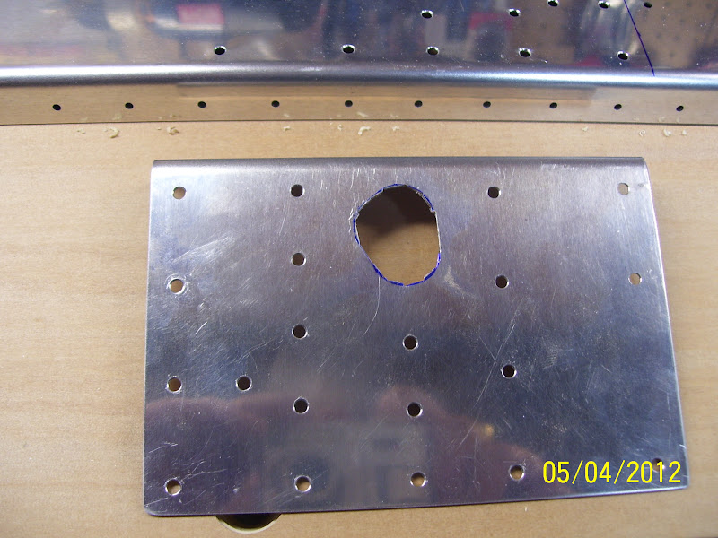
So the next question is how to remove the excess material around the hole. I decided to use the nibbler tool to chip away at the material until I got it as close to the drawn edges as possible. one thing to keep in mind about this is that you need to clean out the hole to the point where you have eleminated all signs of the drawn lines for the hole. I have read some builders logs where they had to go back and enlargen the hole when assembling the pushrods and checking for clearance. My guess is that this happened because they did not continue to clean out the hole until the drawn lines were removed.

This may be a shot of the one for the left spar since this still looks a bit ragged. I was able to take this down to very close to the lines. I find that I can be very surgical using this tool, and I can get jsut about all the material removed right up to the line as long as I am careful about where the cutting blade is placed before I snip.

Here is the right side bracket after nipping it as much as I possibly could.
Next step is to debur the rough edges by running it through the scotch brite wheel. This got rid of the rough outer edges from the nipping tool, so that I could clamp it back onto the rear spar and check my progress.
This next pic clearly shows how much more material needs to be removed. My solution for this final step was to use a small 1/4 inch dremel sanding wheel bit, using the rear spar as a sort of routing guide for the snading bit.

And here is the tool I used in the dremel. I also used the flex shaft for this - much easier to perform fine detailing work than holding the larger dremel tool itself, and worth every penny I spent on it. I just basically worked my way around the hole, keeping the sanding drum as straight up and down as possible. Now some of you builders following my blog might take notice that I am using a silicon based sanding wheel to do this work, which, from a corrosion control perspective, is a huge no no. I will be final finishing this hole with aluminum oxide sand paper, which should remove any traces of silicon in the metal, so I am not worried about this too much.

Other people are using a metal cutting tool that resembles a daisy wheel or a miniature reamer type tool. I ahve some of these but do not have a lot of experience using them, so I opted for the sanding drum, which worked just fine. It just requires patience and a slow methodical motion of the tool, and only doing a little bit of sanding at a time, checking the work repeatedly as you go.
Here is one side after sanding it flush with the hole in the spar. This action also smooths out the edges of the hole in the rear spar, which is also quite rough "out of the box." I also took my edge deburring tool and went around the edges after the sanding was done to smooth them out as much as possible also. The last thing you want happening is the metal on the aileron pushrod getting scratched or gouged as it moves in and out of this hole.

And the other side:

And then just for fund I decided to cleco the gap seals for the aileron and the flaps into position. I am a bit confused and concerned by the fact that not all of the holes are linear. It seems that some of the holes at one end of each of these gap seals is slightly offset from the line of holes for the majority of the part, and I don't know why. What I do know is that Vans has cut releif slots in each part to allow for this type of offset. Guess I'll find out more about this when actually get to the point of attaching these to the rear spar. For now I just wanted to see what they looked like.


Read up onmy instructions for the new spary gun last night, and bought another gallon of acetone. Next comes the fun part of scuffing and cleaning all the rear spar parts.
.
No comments:
Post a Comment