First, I managed to get my airplane-themed drawer knobs installed on my bench drawer. I will most likely paint the drawer front at some point, but this'll have to do for now. I thought these looked very cool.


Here is the top flange of the left wing spar with all the fuel tank skin holes countersunk. The top side is much easier because it does not include the different size holes for the inspection cover plates that are mounted on the bottom. They all came out rather well I think.


This next one shows the back side of one of the smaller #6 screw holes as it appears from the inside or back side of the spar flange. All of the nut plate triplet sets of holes have to be deburred after they are drilled and countersunk. The important thing to note about this next pic is that these are holes that end up coming very close to the edge of the spar, so if you are not careful you maycountersink too far so you need to pay attention to the diameter that you set your countersink tool to. The back side pic is misleading because it still shows that the hole has plenty of edge distance on the spar flange. What you don't see is the other side that was countersunk.

Next are the two different nut plates and the corresponding screws that are used for each one.The smaller one is for the #6 inspection plate screws on the bottom, and the larger one is for the #8 screws that will hold the fuel tank skins to the main wing spar. One curious thing to note about the larger nut plate. It is a K1100, which means that is made with a dimpled cavity to accept a dimple or screw countersunk screw head. The only problem is that these nut plates are installed on the bottom or flat side of the spar flange, so there is no need for using a dimpled nut plate. In fact, I would argue that it provides less concentrated surface area around the screw shank than a normal, non-dimpled K1000 nut plate would. I'm sure this is yet another oversight from Van's. Oh, yeah, I think the other ones are a little cheaper too - go figure.

Next is the partially drilled, deburred inspection hole access plate or cover - 3 per wing for a total of six. See DWG 17A for the RV8 plans (Drawing numbers for other models may vary). I gave you fellow builders that one because I am such a nice guy, since Vans does not mention this drawing where they should in the plans.... go figure.....
The holes that are dimpled on one edge are for the #6 screws that mount to the spar flange, drilled with #28 bit, and dimpled with a #6 dimple die. The remaining holes around the other 3 sides are to be drilled with a #19 bit, and dimpled with a #8 dimple die. Why the different sizes for one inspection plate? I am sure Vans has a reason, but they don't tell you what it is. Go figure.......

Here I have temporarily clamped the dimpled cover plate in place on the spar. There are cutouts in the main wing skins that already allow the space for this plate
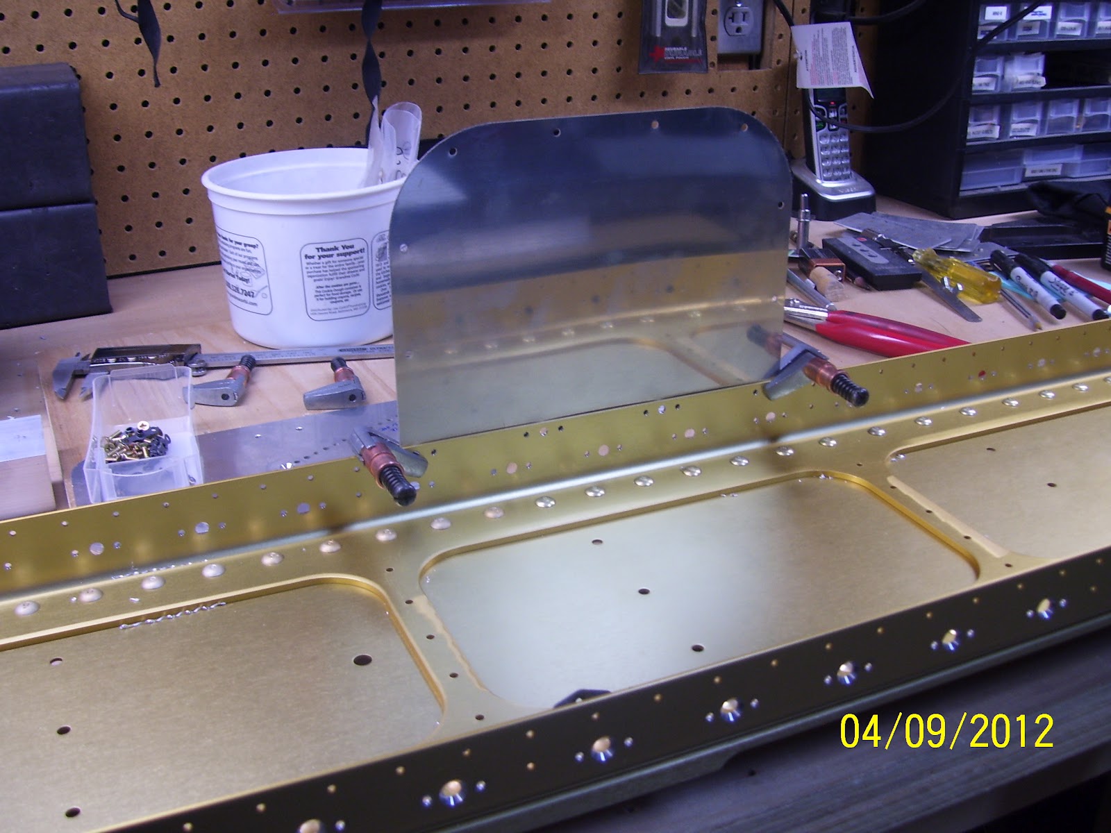
And next I attempted to take a shot that shows the gap between the cover plate and the spar flange because the countersunk holes are not quite deep enough due to their close proximity to the edge of the spar flange. I can probably try to tweak the countersunk holes a bit, but I don't have a lot of room to work with, adn the dimples only go into the countersunk holes are half way right now.

Here is a shot of the 36 inch long, 1.5 inch x 1/8 inch thick aluminum angle that I was able to use to do most of the left wing spar. I did run out of real estate on the angle for the last 15 or so holes on the top, so I ran to HD and picked up another 36 inch long angle, as well as a 48 inch long angle that will allow me to drill more holes than before without moving it. I will use this one on the right wing spar.

Next is a shot I forgot to take when my tech counselor, John Linz came for a visit last week. I have admittedly been very lazy about putting the parts back up on the shelves because I kind of like looking at them all just laying there, ready to be put together and assembled on a fuselage. Someday..........

I set them up this way so that John could inspect each part as much as he felt he needed to.
And lastly, here is my deburring tool. Every one of the drilled or countersunk holes requires a little deburring on both sides of each spar flange. The outside holes I could get with my cordless drill no problem, but the inside holes I could not reach with my drill, even when cocking it 90 degrees into a gun shape. The spar is just not quite wide enough to fit the drill inside the spar web to countersink the inside holes, so I did each one of those by hand. Worked out fine, but it just makes your fingers really sore after a while. Just have one more side on the left spar to debur, then I can switch the left for the right and start the drilling all over again. So I am about half way done with the holes. In the wings right now (pun intended) are the rear spar assemblies and the fuel tanks.

No comments:
Post a Comment