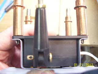
First shows the NAS 1097 oops rivets I used for the two rivets holding the lowest part of the trim servo mounting brackets. Since the flush head on these rivets is very small, it does not take much to countersink the hole with a deburring bit by hand. Notice one of the rivets already inserted in the hole.
Servo mounting brackets, cover plate, and elevator side of the trim tab hinge ready for primer:
Used some tape to mark the 3 5/8 inches of threaded rod that I needed to cut. Used the dremel cutoff wheel and grinder to smooth the ends. Clamped the rod between two blocks of wood to keep from damaging the threads.Took all of a split second to cut the rod.
And after the rod is trimmed and the other clevis is screwed on:
Next is after the mounting brackets are riveted to the cover plate. Shows the low side of the trim servo and really illustrates quite well the reason why you need to use the oops rivets on the low end so that the botom of the trim servo case will clear the rivets. Even with this setup, I will be curious to see how vibration and flight loads on the control surface impact this clearance. You will know if it is rubbing by checking for marks on the bottom of the servo case where the rivets are touching it. No marks is good,means that the clearance is adequate.
The entire trim servo assembly. The clecoes will be replaced when the time comes. In fact, I am thinking about replacing the screws for this with some torx head screws, because everyone says that the phillips head screws get damaged very easily
:
Next is fitting the inboard riblet. The web is inside so that solid rivets can be used. This process was a major pain the ass because I was trying to use some of the existing holes in the riblets and basically reverse-match drill the trim tab skin. A lot of careful measurements taken here before I started drilling holes. This riblet turned out pretty well.
And here is the riblet that goes into the outboard edge of the elevator. Notice the lines I have drawn through the center of each existing hole in the riblet, and the lines drawn after measuring the hole locations on the skin. Before getting to this step, you need to have already fitted the trim tab to the elevator, drilled all the hinge rivet holes on both sides, and filed down the edges to provide the required 3/32 inch clearance between the edges per the plans. Once you have done all that, you can fit the riblet on the elevator.
Next is the flat file I used to finish trimming up the edges of the elevator where the trim tab fits on the outboard end. Just had to do a little bit of filing to even up the edges. Everything looks nice and square.
And finally my latest acquisition of tools. Shown are 3 of the four wire strippers from craftsman professional tools, the 25 watt soldering iron, the slim line heat gun, and the box of assorted heat shrink tubing from GB products that I found at HD. I will be soldering a pigtail extension to the trim servo wires. Probably about 8-10 inches worth or more.
Funny - I am not even done with the empennage yet and I am already working on electrical stuff. One of the things you learn as you start to build the remaining structures of the airframe is that you really need to think about the build from the inside-out. This means having an idea about your wire layouts adn requirements, tubing lines, placement for landing, nav, and position lights, antennas, and so on and so on. The more you have this figured out ahead of time, the easier it will be to put everything in place during the framing process. The trim servo wires will need to exit the left elevator and make their way into the fuselage, and some sort of service plug or connector will need to be created so that it can be disconnected and serviced as necessary.
This last pic is of the outboard end of the trim tab, after I had measured, drilled and set the pop rivets for the riblet. UNfortunately the two rivets on the bottom side did not sit down very well in the dimples, so I tried to drill one of them out. I thought this would be easy, having drilled out other pop rivets on the rudder LE. Boy was I in for a surprise. I guess those pop rivets are not necessarily considered to be structural, and so they are made of aluminum. The MK319 BS flush rivets are apparently much harder than aluminum, and even harder to drill out. I have never seen a drill use up two full tanks of air turning a drill bit and seeing absolutely nothing get drilled out before. Very wierd, and very troubling at the same time, since I don't know how the hell I am going to get this rivet out of the hole.
Anyway, I found some info on VAF about this. Looks like I need to punch out the remaining mandell head and then I am supposed to be able to drill the rivet out. We'll see houw that goes. Sure don't want to screw up the trim tab at this point, so I will take it slow and easy.
Big time snow expected here overnight and tomorrow. We'll see how much more I can get done over the weekend.....


No comments:
Post a Comment