Sunday, December 27, 2009

C Frame ram on top and male dimple die no the bottpm


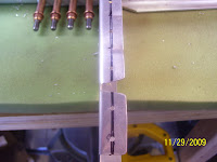
A slightly blurry pic of the dimple die inserted in the bottom of the table as previously described. A level table and a precisely positions dimple die are very important to creating a correct dimple,so care must be taken to set this up correctly before hammering away. Just a final note that the time spent solving the not-wide-enough work bench problem, and finishing the construction of the dimpling table, took a bout 2 days for me to complete. Unfortunately those were the 50 degree days that I might hve been able to finish priming all my parts,which is the last step before final riveting takes place. The cold weather is not helping, and I do have to say that right now I am extremely jealous of those that build airplanes that choose to live in more temperate climates, where they do not have to deal with the cold like we do here in Colorado. Oh well, I just stay patient and find other things to do when its super cold outside! I will show you how parts are cleaned and primed, and the skins are dimpled, in upcoming posts.

C Frame Setup and leveled


This shot is intended to show the setup of the C frame. You can just see the male dimple die, inserted into the same rivet set shown previously, now inserted in the bottom of the C-Frame., which is under the table. The male die just sits slightly above the rest of the table so that the hole in the skins can be inserted. The female die is placed in the ram, and a hammer is used to strike down on the ram which creates the dimple in the skin. All done by hand..... one hole at a time.

Saturday, December 26, 2009

Dimpling the end rib of the left HS


This probably helps visualize everything previously described the best. Here I am dimpling the last 2 holes on the most forward part of the end rib of the left stabilizer frame. The flange is placed over the top of the femaile dimple die clamped to the table, and the rivet gun containing the male dimple die is inserted into the hole of the rib flange from the top side. Just a few second burst from the gun is all that is needed and the dimple is created.

Special Rivet Set and Male dimple die


This is a special rivet set that came with my C-Frame which I also purchased from Cleveland Tools. The male dimple die is inserted at the tip. The other end of the shaft fits into the rivet gun. This is a really great tool for close quarter dimpling or riveting, and it works in tandem with the other tool as needed.

Dimpling in tight places


This is yet another tool I purchased well in advance from Cleaveland Tools. It was not part of the standard tool kit,but it did not take long to understand why it is needed. Especially on the HS, many of the ribs are not very broad or large,and this makes it hard to dimple and rivet certain holes. This tool is known as a close quarters dimpling tool,and allows one to be able to dimple holes in areas where there is 1/4 inch or less width to work with. You simply slide the rib flange over the female dimple die shown at the tip of the tool, and use the rivet gun with the male die inserted to "drive" the dimple into the hole from the top side. My friend Ron purchased a pair of locking plier dimple dies for the same purpose, and so far I have not needed to borrow those, but we'll see Ron! :)

IF you are building an RV adn you do not have one of these, you need to get one!!! Simply one of the best tool investments I have made!!!!!

Dimples


Not a very clear pic. I wanted to show the dimples in the rib flanges. The dimples are necessary to allow the flush rivet heads to sit down flush with the top surface of the part, which is effectively dimpled or countersunk to match the dimension of the flush rivet head, which in this case is always 100 degrees. A set o fdimple dyes are used to create the correct sized dimple for the correct sized rivet. The idea is that the rib flanges are dimpled, and the holes in the skins are also dimpled, and the rivet will sit flush on top of both parts.

2x4 supports for the workbench extension for the C Frame table


Used the same hinges for the supports. Now you can see how they fold up against the frame of the workbench and allow the extension to be stowed.

Workbench extension for C-Frame table Support - underneath


The underside of the solution. This also shows the 2 inch overhang that I purposely built in to my workbenches,so that I could easily clamp things to the bench without the need for a really deep clamp. The 2x4 support is also shown. The hinge for this is on the other side. So, when I do not need the extension, I unlock the bolts, and fold the supports up against the frame, and drop the extension down. Works pretty well.

The problem and the solution


The bench was not wide enough to fit the table!! (30 inches vs. 3 feet,or 36 inches! Whoopie! Now I get to go back and work on solving a workroom problem instead of working on the airplane. I was bummed, but went to work to figure out how to solve this dilemma. As shown, I took a 2x6 and some hinges and created a foldable extension that I can extend or remove as needed. It is supported in the middle by two more hinged 2x4s. I also installed 2 barrel latches, (right side shown) to keep it alllocked into place. As with most all wood that you buy from Home depot these days,it is anything but flat on the edges, bu the middle was flatenough for my needs. Perhaps a couple more hinges on the outside would straighten this out, but its good enough for now. Just enough room for the table legs to sit on a solid surface so that the table can be leveled.

Dimpling table and a required extension mod to my workbench - ARGH!


View from center. Again a reminder,you can double click on the photo to get a much larger view of the photo thatmuch greater detail. From here you see the C-Frame in the center of the table with the ram on top. What you may not be able to see yet is the set holder that holds the other dimple dye on the bottom. This sits flush with the table. The table itself is made of Oak, is 3ft wide x 4 ft in length, has a heavy cardboard surface on top, followed by some very short carpet that is glued onto the cardboard top to keep from scratching the surface of the skins as they are worked on. Note the dimensions of the table, and then note the original width of my workbench, which I designed to be 30 inches,and then all you math wiz types out there can tell me what problem I encountered that I needed to solve. HINT: notice the 3 adjustable legs on the bottom of table, and where they are located.

Back to the work bench!


I mean back to the workbench - literally! This is a pic of a special table kit that ordered from Cleveland Tools. It provides a level surface to dimple and perhaps rivet large parts together such as aluminum skins. The black arm sticking up in the middle of the table is called a C-frame. This is the tool that allows one to dimple or rivet the holes drilled in the skins. The parts shown are all of the ribs and spars that make up the left side of the HS. They have all been dimpled.

Wednesday, December 16, 2009

Found my paint scheme!


I would be remiss if I did not include a picture of an RV-8 called Nifty. This is extremely close to the paint scheme that I invisioned for my aircraft. Luckily I found a pic of one that is already flying. I will have some different trim details, and nose/tail art on my aircraft, but this is what I had in mind for the most part. I found this on the RV-8/8-A forum on Vans Air Force. This is the most concentrated gathering of RV aircraft folks on the planet, and a great source of information for those interested in building and flying RVs.

Thawing out from the cold spell - built my C frame table kit

The Colorado cold spell lasted for about 2 weeks, so between the snow and the sub-zero temps I did not get much done on the plane. I have managed to get all the holes deburred on the left side HS, and prepped the skins for dimpling. I purchased a dimpling table from Cleaveland Tools a while back for my C-frame tool. I will attach pics in a later post that will make all this a bit more clear. The C frame is used to reach holes in larger pieces that cannot be dimpled or riveted with the typical hand tools. The table helps support the parts during this process.

The prep work involved is what takes all the time to complete the aircraft. The actual assembly of parts does not really take that long at all. The tasks ahead are dimpling, cleaning, priming, and riveting. Then on to the Vertical Stabilizer assembly.

Wednesday, December 2, 2009

RIght side HS inner rib attach points drilled - edge distance OK again


The infamous 4 hole drilling exercise - this time on the right side of the HS. This one turned out pretty good as well. I don't think I mentioned previously that these 4 holes are predrilled to 3/32" or a #40 drill bit first, and then enlargened with a 1/8" or a #30 drill bit after that. So, between the the two sides, I had to drill these holes a total of 16 times before they were done.

THis pic is taken from the rear of the HS looking forward, which is exactly how I drilled the holes. Note the reference lines showing where the trimmed flange of the nose rib on the other side of the forward spar. Used the same process as in earlier posts working on the left side in order to ensure that holes were in the proper position to ensure correct edge distance.

62 hours on the hobbs now. Center section of HS skeleton coming together


A shot of the center section. All this gets riveted together eventually, and much much later on these two center sections get bolted onto the fuselage. Sounds corny, but I actually dream about that moment - hopefully about 2 years from now or so......

View of HS from the non-skinned side


....and a view from the other side. The wings will each be just a bit longer than this, but that's a bit farther down the road yet.

One skin on, the other skin off - almost a complete airplane part!


So once the left side was driled, it was time to do the right side. The plans do not call for this, but I felt like having some fun, so I took the frame from the left side, and attached it to the right side,just to see what the whole thing looks like for once. The whole assembly for the HS is just over 8 feet long.

Line drawn on the HS702 Forward Spar Flange


Another shot of a line drawn on another part. This one turned out better. The trick is to hold the sharpee in your fingers with one finger pressed up against the bend-side of the flange, and the tip of the sharpee on the center line. Then you simply drag the finger all the way down until you get to the end of the flange. The quicker you do it the less chance there is of the line "wandering." Make sure you hold you guide finger along the BEND-SIDE of the flange, and not the open end. The reason for this is that the bend side remains a relatvely constant reference line that will not change very much as the part is worked during assembly. The other side of the flange will be deburred, adn metal will be removed from this side, changing its characteristics, as well as the center point along the flange.

Drawing a center line on the rib flange - EAA HInts for Homebuilders is GREAT!


So I still need to practice a techique to draw a center line on a flange without measuring every little thing. I learned it on the hints for homebuilders videos produced by the EAA. As shown by the double line, I still need to eyeball the center a bit better. The holes that are drilled are pretty much centered along this line though,so it worked out fine. Edge distance is the concern here. Not enough nad the part can weaken and fracture, too much and the edge curls up and will also not be very strong.

Look ma, its an airplane part!!!


So one of my "followers" asked me to stand back and provide some scale so they can see things better. Just a word of warning here - the only time you will see pics of a part that actually resembles something from an airplane is when they are close to being finished. I will try my best to provide a clear description of each pic. If you have trouble understanding what I am showing, let me know and I will be glad to elaborate or clarify. :)
Here is the left horizontal stabilizer, stood on its rear end end this time - it takes up about 4 feet of my work bench.

Match drilling holes through the skin into both inboard HS ribs


Another shot showing the holes drilled into the front rib. Also shows a nice straight rivet line going down the center section of the skin.

Rear side of the inboard HS ribs shows correct edge distance of drilled holes


The other side of the holes are shown here. It turns out that my approach to lining up the front rib and main rib that I described in earlier posts worked out beautifully. The large forming hole that you see between the two center holes in the vertical flange lined up perfectly with the same hole in the other rib. I will be posting details of how I approached this part of the assembly because it was just a bit different than what others have tried to do, but I found it to be much easier and more precise than what many others are trying to do. I don't know if my procedure will work for the RV 7 or other tail assemblies, but it works great for the RV8. I'm pretty proud of the fact that I did not need to order new parts or rework due to botching this part of the build, as many, many others before me have had to do.

HS 404 and 405 Inboard ribs - holes drilled and clecoed to the forward spar


A shot of a critical rib attach point. The 4 vertically placed clecoes are the focus of this pic. I had to use a 12 inch long drill bit to drill these 4 holes. The instructions said that using an angle drill is best, and I have one of these for my air drill. But, I could not get the drill bit to line up correctly when using the angle drill, so I opted for the long drill bit.
This step is the source of lots of controversy and discussion about how to do it correctly. Van's does not pre-drill any of these holes, and two of them go through two additional layers of metal to connect the ribs to the forward spar flange and the two angle support brackets, so correct measurements and precise trimming of parts, as well as precise drilling of the holes, is absolutely critical here. I had to bend and support the long drill bit with one hand, while running the drill with the other, which also means that the entire part had to be completely secured. I was able to put the leading edge up against the peg board wall to keep it from moving while I applied pressure on the the drill bit against the rib, drilling it from the rear side, or opposite side than the one shown here in this pic. I want to thank Ron and all the others on Van's Air Force that provided valuable info about how this should be done.

Left HS - Inboard RIbs


Remember to click on the photos to make them bigger - you can see much more detail that way. This is another shot of the inboard rib that shows the flutes as well two cleco clamps that come in very handy when clamping parts together. Also notice the pre-drilled holes in the skin. The blue stuf is the vinyl coating to protect the metal from scratches.

Left HS - Inboard Side - RIbs Clamped into Place


The inboard side. A lot of prep work takes place to get this rib all lined up and drilled correctly/

58 hours on the hobbs


A 4 day holiday weekend for Thanksgiving with awesomely warm weather resulted in a lot time to work on the plane. I did not get as far as I wanted to, but, as my friend Ron has already stated in his blog when he got to this point, this where it starts to get fun. This a a pic of the left side horizontal stabilizer with the skin pulled down off the shelf and clecoed to the frame. Lots of hole drilling, dimpling, priming,and riveting yet to do, but getting ever closer.......