After the flycutter episode with the most inboard fuel tank rib, the next feat was to fabricate something known as the trap door on the inboard rib that sits next to the most inboard tank rib. So this is now becoming a process of removing the ribs from the skin to prepare for the final assembly of the fuel tank.
Before I get into that whole story, I wanted to share some fun that I had with my wife a little over a week ago at a place near a local mall called canvas and cocktails. It is a place where you can go and paint something on canvas using water based acrylic paints, and have some alcohol while you do it. An instructor guides you through the process to paint the picture step by step, color by color, and brush by brush. I did this with my wife, my oldest son, and his girlfriend, and had an absolute blast. It "almost" made me brave enough to think that maybe I really can paint my own plane when the time comes. But let's not get into a rush on that just yet....
Here are our finished masterpieces - this particular painting had so many colors an shapes going on that it took longer than usual to finish it - almost 4 hours. But it was time well spent IMHO. Can you guess what it is, and which one do you think is mine or the wife's?
Now the trap door episode. What is it? Well, in aircraft where a flop tube is to be used for the fuel pickup line, and where possible extended unusual attitudes or 0 or negative G flight might be encountered, You have to ensure several things:
1. The engine has an inverted oil system
2. The fuel tank system is designed so that fuel can continue to be delivered to the engine at all times.
Vans standard design is to install a fixed, rigid fuel pickup line that stays in the same position in all flight attitudes all the time. I had decided when I ordered my wing kit to put one flop tube in the left wing and keep the standard fuel pickup tube in the right wing, with the idea that all unusual flight attitudes and inverted flight would be done with the left tank selected so that it takes advantage of the flop tube.
If you have ever built and flown gas or glow powered RC airplanes, you always had to put a heavy weighted clunk attached to a piece of fuel line inside the fuel tank. This allows gravity to keep the end of the fuel pick line inside the tank always accessing the lowest area where fuel resides. The flop tube is basically the same concept, made with some different materials and a few more fittings, but the exact same concept.
Another contraption that is also used to help ensure that fuel is always available and in close proximity to the flop tube is a so-called trap door, that is placed over a small hole in bottom rear of the next closest inboard tank rib. The most inboard rib obviously cannot contain any holes except those that contains a vent line or fuel feed lines that will route fuel to the engine from the wings and fuselage. However, all of the inboard ribs MUST contain openings that allow fuel to transfer from one bay between ribs to another bay. IN addition, the dihedral of the wings also forces fuel to continue to flow to the lowest inboard position in the wing tank, which is right over the corner where the fuel pickup line is located.
By the time the fuel gets to the last bay in the tank where it is picked up and routed to the engine, under normal flight attitudes and conditions it should generally remain in the last bay of the tank, closest to the fuselage. However, when performing aerobatics or high G maneuvers, it is possible that the fuel may attempt to move out of that first bay of the tank and back into the outer bays, away from the fuel pickup line. So to help prevent this, a small trap door is fabricated and installed on that first inner rib so that it covers the hole that allows fuel to enter that first bay in the tank. It is designed so that it opens and closes automatically as fuel pressure is exerted into or out of that bay. Any force that is applied that would allow fuel to be removed from that bay will also close the trap door, while pressure applied in the opposite direction forcing fuel into that bay will also open the trap door. There is no control linkage or motor or wires - it is just mounted with a hinge and a plate that is big enough to cover most of the opening in the rib, and is allowed to swing freely as described above.
Now for the funny part. It seems that my original reasons for wanting a flop tube in the tank may have been misguided somewhat.It turns out that the only time you really need the flop tube is if you intend to conduct sustained inverted or negative G flight. If you perform positive G maneuvers, which most aerobatics are, you don't really need the flop tube, and can get by with the standard fuel pickup line. Further more, if you keep the aircraft coordinated, fuel should always be available in the first bay of the tank, and never allow a condition where the pickup line or tube is un-ported. This then means that the trap door should also not normally be needed either.
Oh well, too late for that. Anyway I still like the idea of the trap door anyway as a bit of insurance to keep fuel in that first bay at all times. Turbulence can have a way of putting you in some very strange flight attitudes - ask me how I know....
So I decided to put in the trap door assembly since I am also going to use the flop tube. It starts with making the door itself from .020 inch thick aluminum from your trim bundle. This is thinner than a pop can and is the same thickness as the skin that was place on the rudder frame. I measured it per the plans and cut it from the sheet using left and right hand sheers. I think this was the frst time that I realize that the left and right designation does NOT apply to which hand you use to do the cutting, but rather the side of the cut that needs to be made and the amount of extra metal on either side of the cut that needs to be kept out of the way of the sheers and the cut. Never understood that, and never used these tools until now.

Next was figuring out where to get the hinge material from. the plans tell you what hinge to use, but they don't specify a part number of if this is supplied already with your wing kit. I learned from other builders that you can use a small section of the same hinge material for the wing flaps. these hinges are 6 feet long (72 inches), and a quick review of the flap assembly plans shows that only 56 inches is needed for the flaps, so they give you plenty of extra hinge material. I measured the length I needed per the plans, and marked the line. I used my Dremel cutoff wheel to cur the hinge, but I had to slide out the hinge pin first, because you need a little extra longer length of the hinge pin so you can bend the ends to keep the hinges from separating.
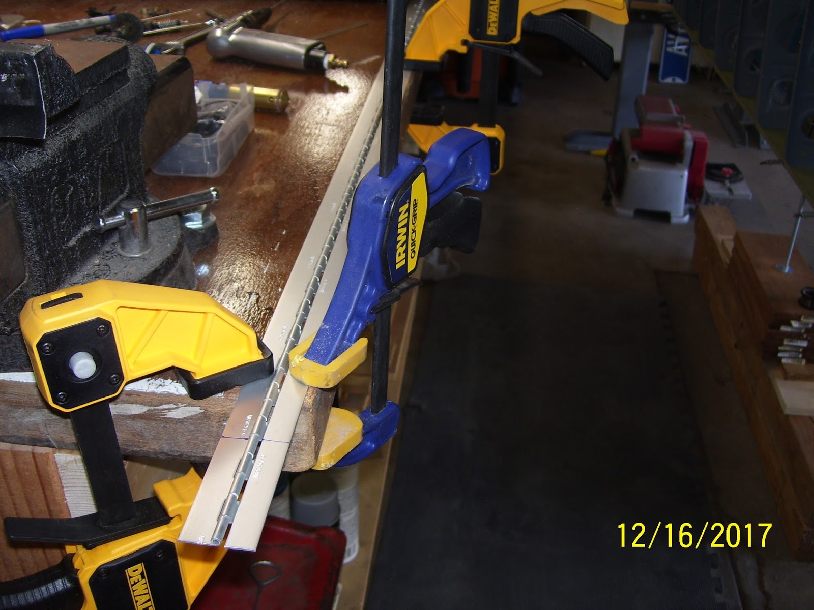
Here is how I clamped everything down to make the cuts:
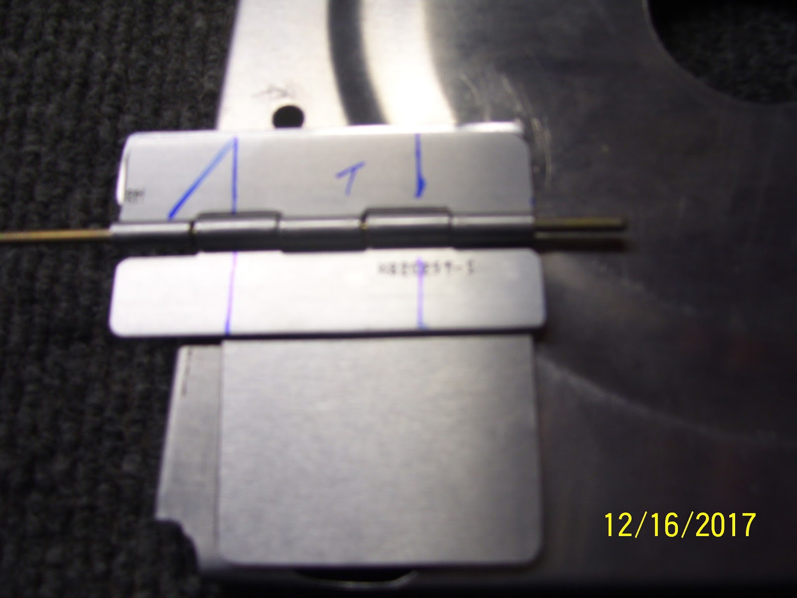
One part that you also should fabricate, which the plans do NOT show, is another piece of .020 aluminum shaped to match the dimensions of the upper hinge half (about 1/2 of an inch wide). This is a spacer that allows the top half of the hinge to sit even with the bottom hinge and the door assembly, and allows the door to close as flush as possible next to the hole in the rib. Here is the hinge, the door, the spacer, and the hinge pin all cut to initial size.
Next the hinge gets trimmed a bit more to match the width of the trap door and to form the upper hinge plate so that it has a small triangle on one end. More about that in a minute:
Here is my first trial fit of the assembly on the tank rib. I adjusted this a bit more later one, but this is the approximate location for the door, very near the rear rib flange:
After figuring out how to clamp the small hinge halves down on the bench so they could be trimmed to their final dimensions, I ended up with hinges that looked like this:
That little triangle on the top hinge half then gets bent 90 degrees to act as a door stop for the door. It cannot be allow to open all the way flush with the top side of the rib, because it may never close again, allowing any fuel that is currently in that first bay to escape into the outer baffles of the tank and away from the pickup line. So to prevent this, the little tab keeps the door from opening too far s that it cannot get stuck all the way open. To bend the tab, I put it in my vise like so:
Then I used a small rubber mallet to bend the metal 90 degrees. I had to position the tab properly in the vise so that the bend would occur in the proper place. the reality is that the tab needs to be a little bit inboard from the edge of the lower hinge and the door, to ensure that the door will always contact the stop and will not get stuck:
By this time I should also mention that I had already smoothed the edges of all parts on the scotch brite wheel and rounded all corners to avoid stress risers - standard deburring procedure. After the bend the parts looked like this:

Next came the painful task of marking rivet lines. I hated this part and it took a while before I was satisfied that I had the marks in the proper position. The plans do a horrible job of showing different pics with different hinge layouts that do not match each other, and they show that there should be 3 rivets on the top hinge and 3 on the bottom hinge. The only problem with this is that there is a huge stiffening ring you know - the one on the inboard rib that I cut with the fly cutter recently. So there is a huge void in the area where the upper center rivet is supposed to go (SO a rivet can't go there). And then the location of the top forward rivet is right on the edge of the rib web just on the other side of the stiffening ring, so getting the location of the rivet right is pretty important because the shop head and the hole both need to have enough room to seat properly.
Rivets for the bottom hinge can be evenly spaced as they all will fit on the rib web with no issues.To resolve this, I decided that the upper hinge could only have 2 rivets, and the bottom would have 3 rivets per the plans. The upper hinge would need rivet holes that are the right at the minimum edge distance of 3/16ths of an inch for an AN426AD3 rivet.The lower hinge rivet holes were spaced 1/4 inch from the edges, giving a little bit more of a buffer. Here are my early attempts to mark the rivet lines. found this to be very tricky because it was hard to get a straight edge on the hinges, because they are small to begin with, and the 5052 H34 aluminum alloy they are made with is very slippery. I remember dealing with this when I had to fab the trim tab hinge. It was a pain then and it is a pain now.

Since I had not had to bend hinge pins in a while, I could not remember how I did this in the past. So I decided to try to put a 90 degree bend in the hinge pin the same way I did the hinge. It did not work so well.
I ended up taking a small block of wood with a flat surface and placing it next to the pin and and then hitting the block of wood with the hammer - worked much better, the pin is much stiffer for obvious reasons, so it took a bit more force to get it to bend, but once it was started it went over pretty well.

Next was another trial fit to mark the final position of every thing after all the parts were final-formed. You leave a small opening at the bottom of the hole beause proseal sealant will be placed in this area of the rib flange, and you don't want the door to be so big that it interferes with the proseal. Also note that this hole goes all the way to the bottom of the bottom tank rib flange.Another funny thing that I saw from other folks build logs is that most folks put bends on the hinge pin on both sides of the pin, but some appeared to only put the bend on one end. Now, if yo put only one bend in the pin, and the bend is placed on the rear facing part of the hinge, that should be fine, assuming that the hinge pin is long enough to stay engaged in the hinge holes if it moves forward and backward, because the bend in the pin will eventually hit the rear rib web and baffle plate. However, I also saw some pics on some build logs where the bond was placed on the forward side of the hinge. IN this state there is NOTHING preventing the pin from falling out and causing potential blockages in the tank. I cold not believe this when I saw it. This pic shows the first bend toward the rear of the rib. I will be applying another bend on the other end when all final prep has been completed.

I decided to align the door with the rear rib flange a bit more. This should be the final position of my trap door. I have about 20 more pics of thos whole process, and if you haven't figured it out yet, this little assembly has taken quite a bit of time to research and fabricate. Most builders only show a finished pic of this door and say "here it is, already installed." Almost nobody provides the level of detail I am showing here. Hopefully this will help you with your build.
In the next post I will show how all the rivet holes were drilled and countersunk and hopefully complete the assembly of this seemingly simple little device.
KPR


No comments:
Post a Comment