Monday, December 31, 2012

Leading Edge and Fuel Tank Cradle Done

I set out to tackle the Wing Leading Edge and Fuel Tank cradle today which is used to support the are the skins that form the leading edges of the wing. part of this consists of the outboard leading edge of each wing, and the other part are the fuel tanks which are also a part of the inboard wing elading edge. They are called integral fuel tanks in that they are designed as part of the aircraft structure.

It consists of a 36 inch base, and 15 inch high by 13 inch wide support brackets, spaced 26 inches apart from each other. The plans say to use 1/2 inch plywood for this cradle, but I had an abundance of 3/4 inch particle board remnant from the shed doors that I completed early this year, so I decided to use that instead. This was basically a repeat exercise that is similar to one half of the wing cradle with the cutouts for the ribs. It is configured to hold either end of the leading edge skins in place while the ribs are assembled.

It is very difficult to attach the partially bent, spring tensioned leading eadge skin just by forcing it around the ribs with your bare hands. I have a video that shows what must have been an early method of doing this where the LE ribs are attached to the main wing spar, and then the skins are attached to the top side of the ribs first, followed by the bottom side. The plans simply say to perform this same assembly by using the LE cradle to force the LE skins into the correct preliminary shape of the rib, land the ribs are clecoed together in the cradle. ALl this makes me think of is the times that attached the HS and VS skins, which were also spring tensioned by design. I sure hope I do a better job of riveting the LEs together than I did with the HS and VS.

Anyway, here is a series of pics showing the steps I took. I also deviated from the plans after reviewing many commnets on VAF complaining that vans design for the cradle appears to be unstable, which I was inclined to agree with when I realized how much force I may need to apply to get the clecos inserted correctly the first time.

First was reviewing the plan dimensions to determine how I would modify mine:

 
Then I set out to make the two end pieces that will be cut out to match the ribs for each leading eadge. It is hard to see my measurement markings on the wood, but the I basically used the existing width of 16 inches (Vans calls for 15, but a little more length here is actually a good thing). I did cut them to 13 inches wide per the plans. The tricky part is where to position the rib. I decided to use the rear flange of the rib and tried to align it parallel with the edge of the wood, and then I traced the rib pattern onto the wood.
 
 
Below is my method for cutting out the rib area with the jigsaw. I had to reposition the clamps periodically to provide enough clearance for the jigsaw to complete the tight turns at the front of the rib:
 
Next was my modification to use 2x4s as a corner brace for each bracket:

 
Then I clamped each of the brackets to a wide flat piece of particle board (36 inches long x 16 inches wide). ONce each braclet was clamped to the base, I flipped this assembly over and screwed the base to the 2x4 corner supports:
 
 
The inside edges ofeach bracket are supposed to be 26 inches apart, and mine are as well. This is supposed to allow the skins to be inserted so that the rivet lines for each rib are clear of the brackets for clecoeing and riveting.

And here is the finished product:


The base can then be clamped to the work bench. I may still need to sand the insides of the cutouts a little bit and put some tape or someing over the edges to prevent the skins from getting scuffed or scratched. That was enough for today, however, since the weather forecast around here for New Year's Eve is about 0 degrees. Tomorrow I will see if I can brave the cold long enough to reposition the LE skins from the shelf onto the work bench. Then I may even bring down the left wing spar to prepare for match drilling the main ribs to the wing spar.

Wishing everyone out there a safe, happy new year, hopefully filled with lots of airplane building and flying fun!

Sunday, December 30, 2012

Wing Cradle Done - Well Almost....

I was able to finish mounting the cross members on the spar side of the wing cradle today, and I also mounted the four furniture dollies so that it now has wheels. I was then able to re-arrange everything on the one side of the garage  so that it fits neatly out of the way until I have some wings to actually slip on to it. I still need to cut some slots on the spar side for the main wing spar to rest on, and figure out how to attach the carpet remnant on both ends, but that can wait a bit I think.

Here is set of pics showing the almost finished cradle:


Next on the list is to make a couple of supports that are used to attach and match drill the leading edge skins for the wings and fuel tanks.  Then I can work on the final grinding and prep of each of the four wing stands. And then I can work on clearing off the mess on both of my work benches so I can get the main wing spars off of the shelf and start match drilling them. It's nice to be focusing on building again for a change, even if it is cold as hell outside. If anybody has or knows of a way for me to get cheap or free 24 inch wide R38 faced Owens Corning insulation for the garage I am all ears. Otherwise that little project promises to cost me upwards of $1,000.00. The last pick also shows the space where I will be mounting two of the four wing stands, so as I progress this same shot will start to show a wing in progress hopefully in the not-to-distant future.

Saturday, December 29, 2012

Got My Metal Wing Stands Today!

I made a trek up north to fellow RV-8 builder Aaron Miller to meet him and his Dad, Ron Miller to pick up my all metal wing stands. I wasn't sure what to expect when I got there, since I don't really know the first thing about wht it takes to weld things together. All I say is that I learned an awful lot about welding today, and aside from the garage being about as cold as mine is right now, it was an extremely educational experience.

This is a personal shout out to Aaron and his Dad Ron with a sincere THANK YOU for taking the time (turned out to be about 5 hours total) to weld my wing stands together. Ron even let me dawn all the welding gear and taught me how to weld the last two seams on my wing stands. Here is a shot of Ron hard at work:


I learned that Ron and his wife are devout tool people, especially when it comes to welding gear. Ron used a process called MIG welding. No, I am not going to try to dig out all my Airventure welding forum material from a couple of years ago to explain what all the different welding acronyms mean. What I can tell you is that he plugged this MIG welder into a 9000 watt capacity generator, and a grounding clamp was attached to the metal being worked so that when the welding tip was engaged (trigger pressed) a very high current circuit is completed which melts the metal and welds everything together.

I also learned that welding helmets are even more cool on the inside than they look on the outside. There is a lot more to these helmets than I ever realized. And yes, for all the welding pics I shot and for all the welding that was allowed to observe, I did so while wearing one of these helmets. Failure to do so could make you go blind from the intensity of the light that is produced, which the picture does not really adequately display.

The basic process for all this was to grind small angles along the edges of the iron angle pieces as well as the edges of the posts, to clean the areas to be welded from any contamination and to serve as flow channels into which each weld could flow between the parts being welded. Then everything was clamped together, checked for square  and for centering against the post, add then the welding began.

I was put to work almost immediately on the "grinding station" where it was my job to channel and clean each of the 90 degree angle iron pieces that serve as the mounting base for each wing stand. These were then given to Aaron where they were clamped into position, and Ron did most of the welding.

There were some bumps along the way. One of the welder tips was compromised so we had to replace a tip at one point, and then we ran out of welding rod at another point. This "rod" is actually .030 wire that is continuously fed into the joint being welded through the gun that is held by the welder. Luckily Ron had all the necessary supplies for us to continue welding.

Here is a shot of the generator that was powering the MIG welder:


And next is Aaron with a surprise look when I snapped this pic. Sorry bout that Aaron. You were so busy moving around getting everything prepped that I had a hard time getting a good action shot of you:


I think this next shot of Ron is after the welding was done, and were now starting to play with his new plasma cutter. This thing actually slices through the steel and makes very precise cuts. Aaron had wanted to trim off the upper corners of the 90 degree angles on his wing stands ebcause he found that his foot tends to trip over them while he works on his wings. He asked if I wanted to do this on my stands, and I said certainly. So we proceeded to experiment with the new plasma cutter on my stands first. Unfortunately, several seconds after starting to use the plasma cutter, the generator gave out and would stop running. We were getting a power spike or something and could not figure out why. So Ron resorted to checking the manual - when all else fails..........


I am going to get some better pics of the finished wing stands that I will post tomorrow, but this last shot shows a long distance pic of a completed one still sitting on the sawhorse in the background. The nagle pieces were roughly 18 inches long, and the posts are about 66 inches tall. They also weigh at least 80-90 pounds a piece. One thing is for sure, once I get these babies secured to the garage floor they won't budge from there until I am ready to disassemble them after the wings are done. These posts will serve as a great platform for the fuselage as well, and also as a painting platform, should I decide to take on that task later on down the road. They were not cheap for set of 4 compared to the standard wood post method, but they are well worth the investment as far as I am concerned.


I still have some grinding work to do to cleanup the bottoms of each stand so that they will sit as flush as possible to the concrete floor. I also need to drill the mounting holes, and then scuff, prime, and paint each one to prevent corrosion from setting in.

Again, a huge thank you to Aaron and Ron, and even Aaron's wife Lisa, who kindly made snacks for us to eat once we finally made our way inside after freezing int he garage for several hours. That was most appreciated. This is just another example of the kind of people that I meet that are building their own airplanes - first class folks all around. This was a really great day! Wing cradle is almost finished as well - more on that tomorrow.

Friday, December 28, 2012

Wing Cradle Progress

Today I was able to make some pretty good progress on the Wing Cradle. I am going through the trouble of detailing this because Vans drawings for this are horrible, and because I only seem to get a lot of pics from other build sites, but no details on how exactly this thing is put together.

The next step was to attach the bottom 2x4 supports to each of the panels. I started by drawing the center line (18 inches) down each panel. I then took each of the 2x4s and clamped them in place, screwing them to the panel while keeping in mind clearance for additional screws that would be added later for attaching additional cross member supports on the corners of each panel.


I staggered the screws for the bottom 2x4, which is placed flush against the bottom of the panels.

Once the first 2x4 is secured to the bottom of the panel, I flipped it over and placed the second 2x4 into the position shown below:


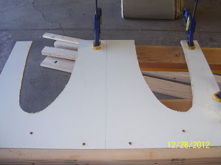
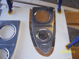
I screwed this bottom board into the other 2x4, and then took a W709L and W709R end rib and used it as a template to draw the outline for the leading edge panel of the wing cradle.


I placed the wide end flange of each rib flush with the top of the panel and drew the lines. Vans offers no dimensions in the plans as far as the spacing between the ribs is concerned, so I took a guess from looking at the drawings in the plans and from other pics of completed cradles from other builders. The concern was the amount of space on the outer edges of the top of each panel, since there would not be a lot of material there. I ended up with about 3-4 inches on each outer edge after I removed additional wood to account for the width of the carpet that will be inserted in each cut out to cushion each wing leading edge.

The next shot is a 3/4 inch extension to the lines drawn around each of the ribs. This is the additional amount of space I added to each cutout to allow for the thickness of the pile carpet remnant I have had lying around in the garage for years now. I used the ruler to make marks around the drawn edges and then connected them via freehand as best I could. This should leave enough space to add the carpet to each cut out, and provide some measure of shock absorbtion to the leading edge of each wing while it rests in the cradle.


Both cut outs are ready to be cut with the jigsaw


And here are the cut outs after some relatively quick work with the jig saw:


Next are pics of the carpet remnant I intend to use:


And finally I fast forward a bit to show the 8 foot long 2x4 center support attached to both panel ends, and I managed to get 3 of the 6 total support brackets mitered and attached to one side of the cradle.

The support brackets were measured as follows:

The two side supports were between 24 3/8 inches and 24.5 inches long, mitered at 45 degrees on both ends. One side attaches to the inner 2x4 panel support, and the other end is attached to the center 2x4 as shown above.

The center vertical panel support was cut from a remnant 2 foot long 2x4, again mitered at 45 degrees and secured with screws - the top side was drilled and screwed from the outer side of the panel, and the bottom attach point was into the top of the long center 2x4 support.

ALl that remains is the 3 cross members for the other side of the cradle, the cut outs for the main wing spar ends on the other panel, and adding the carpet and the cut outs on both panels, as well as the furniture dollies to the bottom of the frame. SHould be able to finish it up tomorrow morning.

Thursday, December 27, 2012

Building the Wing Cradle - FINALLY!

With the space in the garage taken care of, I now need to make some fixtures that are long overdue for my build. The first is the Wing Cradle, and the second is the leading edge/fuel tank stand. I will be picking up the metal wing stands from Aaron on Saturday, so hopefully I can get the wing cradle done before then. A quick note about the fixtures. Sometimes folks intermix the terms cradle and stand, as well as the word "jig." Just to clear some things up, The wing stand or jig is simply the two posts with some angle iron supports to mount the wing spar so that the wing skins can be attached to the ribs as easily as possible. The wings are built vertically as though they are climbing straight up vertically. So the words "stand" and "jig" are used interchangeably. The wing cradle, on the other hand, is a fixture that will store the completed wings once they are finished. The cradle stores each wing on the opposite position from the wing stand, or with the leading edge of each wing facing straight down. The cradle is what I am working on now.

Before I show the pics, I just want to extend a shout out to my friend and fellow RV8 builder Steve Riffe who has some great pics of his wing cradle at the very begining of his Wings section of his builders log. Without his pics I might have had to call Vans to figure out how the hell to make it since their plans for this are less than adequate IMHO.

First step was a trip to the local airplane store (Home Depot) to buy a bunch of wood and some hardware.


Shopping list for the cradle:
5 each 2x4x8s
1 each 1x6x8
3 each 1x3x8s (these are actually for the frame for my newest priming table from the cardboard box that my recently installed screen door came in).

Assortment of 1 1/4, 2, 2.5, and 3 inch deck screws.

Additional items already in house:

2 particle board panels 2 foot x 3 foot - After removing the doors from my 2x4 foot storage shelf, I noted that the dimensions of the doors are about 2 feet wide x 5/8" thick x 6.5 feet tall. You need 2 separate 3 foot x 2 foot panels, one on each end of the cradle, to support the wings on both ends. One panel has notches cut in it to support the wing spar at the root of each wing, and the other panel has cutouts for the leading edge of each wing.

A set of casters to allow the cradle to be moved around as needed. I plan on using the 4 sets of furniture dollies I used to support the Wing kit crates until I was able to purge them and store all the wing parts elsewhere.

The shelf doors will serve quite well as the panels on either side of the cradle. the doors are 2 feet wide. The leading edge ribs on each wing extend out from the spar about 17.5 inches, and the 2 foot width allows enough space for that as well as the space required for the supports on the bottom of each panel for strength. One note about Vans Plans for all this. They are contained in DWG 12A. Mpst of the drawings are labled as being 1/12 scale, but I found that one of the drawings that specifically mentions the height of each panel does not seem to be drawn at 1/12 scale at all. This becomes misleading, and like so many other areas in the plans, is also entirely inaccurate. I wish they would fix some of these things....Nothing new....

Here are the door panels that I cut down to size for the wing cradle. Note the two leading edge ribs. These are the end ribs for each wing, W709 right and left. They are used to draw the initial template for the cutouts on one of the panels:


The above pic shows the orientation of the wings as they will sit inside the cradle - the upper part of each wing will face inward to each other, adn the bottom parts of each wing will face outward. The wide part of each rib is where they will attach to the wing spar, and cutouts will be made pretty much as shown in the pic, with the wide end of each rib at the top of the panel. I may try ot make them a little deeper to allow the wing spar flanges to be supported by the sides of the panel so that the stress is placed partly on the wing spar and not solely on the leading edge ribs.

Next is measuring and setting up the fence to cut each door panel to the correct size. I used my circular saw for this.


And here are the finished panels after the cut. The holes that you see are recessed holes that were in the doors to support the hinges thart came with the shelving unit. These will be covered with 2x4 or other support wood frames when the cradle is complete so I am not cerned about these extra holes being there:

There are 2 sets of 3 foot long 2x4s at the bottom of each panel. This is part of Steve's cradle design and is not what is drawn on Vans plans. I happen to like Steve's design and so I plan to copy it.


And finally a shot of some of my Xmas booty I acquired for the build. I received a set of 4 books written by a well respected EAA member by the name of Tony Bengelis. This ought to keep me busy for a good long while. His books are easy to read and contain a wealth of great tips and trickes and information for all aspects of building an airplane. Worth every penny.

The other plier-looking item is an automatic wire stripper from Ideal, part 45-097, which contains the dies for most of the wire sizes I will be using for the airplane, including the 26 gauge wire for the trim servo. After agonizing over this for quite a while I was able to track down the right part number and set of dies that will handle the small 26 gauge wire of the trim servo wire bundle. Now I can add the extension to that wire bundle with confidence that I will not be removing any strands of wire when they are stripped. I also recieved a spare set of dies:

Rearranging the workshop again

As I predicted a long while back, I have waited until it is as cold as it has ever been this winter to get started on the project again! Why I do that I will never know, but that's just the way that it is I guess. The first order of business is to rearrange the work shop in preparation for the wing stands that I am about to receive thanks to a local fellow RV-8 builder Aaron Miller.

I became acquainted with Aaron in much the same way that I have become acquainted with so many new friends while building my airplane - a post by Aaron on VAF contained some pics of some metal wing stands that I have also seen on some other builders sites. I had been agonizing over exactly how to do this for my project. The choices are to do the 4x4 wood stand or to bolt some metal posts to the garage floor.

I had resigned myself to using the wood posts because I did not know anyone locally that had a set of metal ones or knew how to make them - until I saw Aaron's post that is. We have since exchanged mnay emails and it looks like his Dad is going to weld me up some brackets this weekend, which I will then mount to the garage floor after drilling about 16 holes in the concrete to anchor them down in just the right spots.

Aaron's builders log is located here. Another site that contains the specs for the same stands is from Rudy Greiling in South Africa. I will need to rent a rotary hammer drill to drill the holes for the anchors that will be used to secure them to the garage floor. I will be using RedHead 3/8" x 2 1/4" concrete anchors, 4 per stand for a total of 16. I will drill 4 half inch holes in each mounting bracket for each stand to allow some wiggle room in case I don't get the anchors drilled in just the right spot.

But before I can get to that, I had to determine of I would even be able to build both wings at one time or if I would only have enough room in my 2 car garage to build them one at a time. After a long bit of eyeballing the space inside my garage, I decided that I could in fact build both wings at the same time AND still manage to get both cars in and out of the garage when needed. IN order to do that, I needed to rearrange several things.

I basically determined that I could turn my large white storage cabinet 90 degrees and remove the 2 foot wide doors, adn then I could trade positions of my freezer and my other 2x4 foot storage shelf, and this would open up the area enough to allow me to setup the second set of wing stands. I also moved my table saw out to the shed since I do not use it that much for the airplane anyway.

Now for some long awaited pics:

First is the chaos on the work benches after cleaning all the stuff off of the shelves so I could move them:


And here is the freezer moved from one side of the garage next to the compressor on the other side:
 
And my parts shelve now located on the other side of the garage where the freezer used to be:
 
This little switch made it easier for me to get my car in the garage and also gave me more room on the other side to place the second set of wing stands. The first set will be located in front of a parallel to my work benches. I will have to find another place to store the long table I have been using, and I think this will make its way to the back porch for a while. Funny how switching a couple of things around can open up new opportunities.

Thursday, December 13, 2012

Using available resources

"Normal" people would look at this next photo and say .."so what, it's a box." Builders of experimental airplanes would look at this and say "...Cool! another box I can use for priming large parts!"


Actually, this is the box that the new screen door came in that I am currently in the process of installing on my front door, part of which can be seen in the background. As I was opening it up, two things struck me:

1. This is quite a large piece of cardboard
2. This should make at least one, and possibly even two separate priming tables that will be able to hold a large number of wing parts.

The next step in the build from where I left off long ago is to scuff, clean, and prime all of those straightened wing ribs. This will require a lot of elbow grease and probably several days to complete. One thing that helps to complete this work is to have a large enough work area to setup adn prime all the parts without having to do them in smaller batches at a time. This box will allow me to place several ribs on it, and with this and the two other priming tables I already have, I shold be able to get the priming work done fairly quickly. I will need to make another box frame with more wire fencing, and then I can proceed.

It's funny how events of every day life can sometimes generate opportunities to help complete this project. Time to start building an airplane again. The new goal will be for both wings and both fuel tanks to be complete by the time Oshkosh 2013 rolls around next summer.

Tuesday, December 11, 2012

Fundamental Decisions About Cockpit Layout

This post starts with a recent attempt by me to search VAF for some info about Wing Stands and Jigs that may have been posted by Paul Dye (VAF user Ironflight). This is a gentleman whose wealth of knowledge I have come to greatly respect throughout my experiences thus far with building the RV8. He contributes articles frequently for Kit Plane Magazine and was a systems engineer for the Space Shuttle and Space Station programs at NASA. If anyone knows about all things "experimental" when it cmes to aviation - he is certainly one of those individuals.

Anyway I had heard that he had a simple wing jig solution and I was trying to find a post to that effect - that is until I stumbled on a couple of posts from him back in 2006 after his RV-8 Valkyrie was completed and flying. Doug Reeves, founder of VAF, had captured several pics of his panel layout, and as I started studying the photos there were some comments about the reasoning behind his panel layout that I did not want to lose reference to.

So this post is now dedicated to a small tidbit of information about some things that I must not forget when the time comes to figure where all the goodies will go in my instrument panel and various consoles on either side of the pilot seat. I like Paul's reasoning for why he put certain things in certain locations, and will plan on emulating those same considerations in my own plane when the time comes. Here is a list:

1. Overall he tried to group common items in the same locations to make it easier to locate systems with similar functions.

2. All primary electrical switches are located on the right console next to the pilot seat

3. All engine-related controls are placed on the left console, including the engine monitor.

4. He used a rail system on either side of any essential electrical switches to provide a bit of stability for manipulating the switches during turbulence - a technique used extensively at NASA. Gee, I wonder why?! The rails provide a platform to rest your fingers against to help actuate the switch, and it also prevents inadvertent activation of a switch by bumping into it with your hand or your knee, etc.

5. He placed his avionics that require the most interaction with the hand and fingers so that his dominant hand performs the actions such as turning small knobs or pushing small buttons, etc. He discussed this with some human factors engineers at NASA after initially planning to place the radios in the opposite location. His initial thinking was that his dominant hand should be focused on flying the plane so that it would be on the stick, and the weak hand would do all the radio switching and tuning work. He was advised to change his perspective, and allow his dominant hand to take care of the fine motor skill work, and the weak hand to focus on the joystick work. For me this means that the radios and GPS should be on the right side of the Primary flight displays if at all possible.

5. Then I encountered some interesting tidbits about nav/strobe combination lights. I noted that Paul seemed to have a 3-position switch for his strobes - top was ALL, middle is OFF, and bottom is TAIL ONLY. My current thinking was to put a combination red/white beacon on the bottom of the fuselage if that will satisfy the FAA requirements for visibilty to the rear. I also finally found post in the builders log from someone else that confirmed that the Wing tip Strobe location that Vans provides DOES NOT meet the requirements for rearward visibility of the anti-collision loght system, and therefore this discrepancy in their design needs to be addressed somehow. Putting the strobes in the wing tips, as most people do, only allow visiblity from the side and the front, and NOT from the rear. This is, in essence, a violation of the relevant FARS that I have reffered to in previous posts that is excrutiatingly specific about the distance, number of lumens, and angular visiblity requirements for the required exterior light systems.

6. One last thing that I noted about his overall panel layout, as well as those from several other builders, is that he retains the basic scan format with his backup airspeed indicator positioned on the left side of the EFIS display (which provides attitude display in addition to the other information when everything is working), and the altimeter on the other side. The backup attitude indicator is located elsewhere on the panel. I have seen several builders emulate this configuration, and then I have seen others that tend to try to keep all 3 backup instruments in one line across. The problem is that the EFIS is always in the way in the small panel space provided by the RV-8. This makes positioning all 3 backup instruments together in a location that will be readily viewable by a pilot that needs to use them in an emergency a bit of a challenge.

There are numerous schools of thought out there on the positioning of the backup instruments. One interesting insight is that if the backup instruments are located in a position that is readily viewable by the pilot most of the time, then the they tend to focus on the back up instruments instead of the EFIS for primary flying tasks, even when the EFIS is working perfectly. I am almost of the opinion on this that I would rather have a backup EFIS on a secondary power system so that not matter if the primary EFIS fails, I am still maintaining reference to flight instruments from a similar display. Works pretty well if you have the extra cash and the extra panel space to go with it such as in a side by side RV like the RV-7, etc. This does not work as well in the RV-8, where panel space is at a premium. Anyway, when the time comes, I may keep the backup round dials in a single line or I may break up the attitude indicator - just not quite sure how I will decide to do that yet.

There was also a comment about putting a combo nav light/strobe in the tail. Somebody mentioned that this is a major distraction for a low wing airplane at night, with the light reflecting off the wings from the rear, possible entering your peripheral vision. So he recommended not putting a strobe in the rear. I am hoping my decision to place this system on the bottom of the fuselage eliminates this problem, but I am worried about electrical noise affecting the ADAHRS unit for the EFIS, which will also be mounted in the rear of the airplane.

So much for checking out wing jigs! Here is the link to the post that contains Ironflight's panel photos.

IF I can just shed some of the cold weather that finally appeared in Colorado I am just about ready to re-engage in the wing work. Personally I will be glad when the holidays are done and over with - I need to get back to building an airplane.

Sunday, December 2, 2012

Finally posting pic of the new air hose reel


My account with Google finally kicked in and I now seem to have access to my additional space for pics. So here is the pic of the hose reel that was installed in the rafters of the garage last week.