Wednesday, December 22, 2010

More VS riveting pics


This is not the best pic, but if you look closely at the bottom you will see some flush rivets (appears as though there are no rivets at all) on the spar, and then you see the shop heads from the remaining AN470 universal head rivets. I bucked every single one of these rivets. I find that the spars and ribs are relatively easy to rivet together. Putting the skin on is a different story.


This pic shows the otherside with shop heads of the flush rivets. Flush rivets are installed on the bottom part of the rear spar because this must sit flush against the very last bulkhead of the fuselage where it is bolted into place during the final assembly of the tail. The round headed rivets are used for the remainder of the rear spar since they do not interfere with the fuselage. I had to drill out and replace one of the flush rivets for one of the hinges shown above. For some reason it was the only rivet that slipped out of the hole on me while I was riveting it into place. My attempt to continue to push it back into place was not very successful, and it resulted in a much wider factory head than it started with, and I over-drove the rivet on the other side so the shop head was not formed correctly either.

I managed to get it drilled out without messing up the spar, and replaced it with a much better looking flush rivet. I am feeling much more comfortable with the rivet gun, and I am now much less intimidated when driving the 1/8 inch diameter rivets. They are still very difficult to drill out, however, so I prefer to try to set these rivets correctly the first time.

178 hours Riveting the VS Rear Spar


Finally pounding rivets again on the Rear Spar of the Vertical Stabilizer. Here it is clamped to the edge of the work bench with hinges and reinforcing plate riveted together. Click on the pic to see a larger one with more detail. The green frog tape covers the holes where the ribs from the rest of the frame will attach to the rear spar. You can't put rivets in these holes yet, so the instructions wisely tell you to put tape over them so you don't accidentally rivet them by mistake.
For some reason I continue to have a problem setting good rivets where the hinges are located. Good news is that I only have to drill out about 5 rivets on this assembly and re-do them. A significant improvement from my last riveting adventure. It felt good to pick up the bucking bar and the rivet gun again. It has been way too long.

Thursday, December 16, 2010

174.5 hours VS frame primed


Need a little more light when you prime? Just add a few Xmas lights in the background! Here is my priming setup once again, with the wire drawn across the garage, parts hung, and the 1x2 collapsable frame supporting my floodlights. Oh yeah, and my cars parked precariously close to the whole operation - not recommended when working with acid etching primer products. Luckily I kept all the primer on the airplane parts.
A much better "first run" working with the primer this time. The trick is definitely to mix the crap out of the primer and the reducer to ensure that it has the consistency of skim milk, so it will run off the end of my mixing stick for a second or two. You don't wait to start priming after mixing this stuff like you might do with epoxy-based primers. You just pour it in the cup and go.
Here are all the VS frame parts all primed and ready to be riveted. I have also masked the inside of my VS skin and will use the 7220 self etch primer in the can to prime the parts of the interior skin where the flanges of the spars and the ribs will attach to it, just as I did for the HS. I expect to have a completed VS and a partially completed rudder by the end of this weekend.

Wednesday, December 15, 2010

172 hours - Cleaning and Priming the VS parts

Finally got the skeleton of the VS primed tonight. I'll add pics tomorrow. I used the same process as as I did for the HS - hang the parts, prep the primer and the spray gun, prime the parts, then wash, rinse, and repeat. The amount of dirt and grime that comes off the parts when wiped down with a microfiber cloth and acetone still amazes me. You have to keep cleaning the part until all that grime no longer shows up on the cloth, to ensure that the primer will adhere correctly and will not come off. Full respirator gear is also required for the acid etching primer that I am continuing to use. As long as it is mixed correctly it seems to go on fairly well.

Next is the masking of the inside of the VS skin and spraying of the 7220 etching primer where the frame will contact the skin when everything is riveted in place. Again, it's the same process I used for the HS. Then it's finally "pounding rivet" time again! The goal this time will be to keep from marring the skin up so much and to avoid denting the skin like I did last time when I started riveting the HS.

The completion of the rudder assembly will follow soon after, and then the right and left elevators. I'm really itching to get started on the wings!

Sunday, December 5, 2010

Bending brake for the trailing edge of the control surfaces


Warning! Anyone that is building an RV7 or different model of RV will be performing a different procedure to complete the Rudder trailing edge. This is because the RV7 uses a two piece skin and a metal wedge to form the trailing edge of that rudder. The RV 8 has a one piece rudder skin that has a partially bent traling edge that must be finished after the stiffeners have been riveted to the skin.


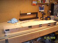
To accomplish the final bend, you need to build another homemade tool called a bending brake. It is basically nothing more than two long pieces of 2x8 attached with 3 inch hinges from HD. My math skills are a little lacking as I tried to determine the precise centerline placement of 5 hinges on a 49 inch long board. so I divided 49 x 5 and came out with about 9.8 inches. So I measured out 9.8 inches from one end of the board, and started attaching the 5 hinges, only to realize that I needed a 6th hinge based on the measurements I had taken. So this turns out to be a "divide by and add one more" scenario. You can see the remaining spot for the missing hinge in the top photo. My only concern now is that I don't continue to make this same mistake when I have to measure and layout rivets on other parts of the build. Oh well, one more trip to HD and she'll be ready to go.
You basically open the brake wide enough to insert the rudder skin trailing edge, leaving about 1/2 to 3/4 inch gap between the skin and the hinges of the brake, and then you "wanker" down on it" as the aussies would say, until you achieve the final bend. The trick is to make this bend as straight as possible, and to keep from bending it too far. I was very concerned about this because the plans lack any detail about the expected radius of the trailing edge after the bend is made.
I decided to turn to my eldest son for help. He is about to graduate high school, and has completed several college-level math and science honors courses. I wanted to determine a bit more definitively what the finished angle and corresponding height measurements of a specific point would be, to help me determine appoximately how far to apply the bend. I told him the front spar would measure about 3 inches high at it's widest point, and the skin width was about 20 inches. We also figured that the point where the leading edge of the skin attaches to the front spar is close to a right angle (90 degrees). This is not entirely accurate, but was good enough to apply some formulas for experimental purposes. He applied some trigonometric functions and determined that the finished angle would be about 8.53 degrees, and that the height of the front edge of the bending brake should be about 1.2 inches high when the bend is completed. You are not supposed to have anything attached to the leqading edge when you perform the bend, and I was concerned about knowing when to stop bending. That is why I wanted some measurements to go by. I am just simply amazed that there are mathematical ways to apply some precision to this task without it being such a guessing game.
Vans also told me that the radius of the rudder trailing edge bend should be about 3/32 of an inch, and explained that the distance of the trailing edge from the hinged-edge of the brake will need to be shorter or longer if you choose to shim the hinged edge of the brake up a bit to prevent bending the trailing edge too far, as some builders have also done. I am still concerned that I will need to tweak the bend a little after it is attempted, since many others have needed to perform additional fine-tuned bends using other hand tools like a hand seamer. I would rather it be done without the need to "tweak" anything, but I certainly don't want to ahve to order a new rudder skin either. Nerve-racking stuff when you have never actually done it before, but I'll get through it.
When I get closer to actually performing this step I will refine and double check the math numbers to ensure they are correct, and then we will see if it works......


Straightening VS Rib Flanges - Homemade bending tool


It appears that I neglected to include some pics of a homemade rib flange bending tool that I built for the purpose of straightening the rib flanges so that they are 90 degrees perpendicular to the web. this is important because the skins must lay on the rib and spar surfaces to create a smooth, laminar surface for the air to flow over. If the flanges are not aligned correctly, the part will contain rises and valleys in the skin. This will negatively affect the ability of the air to flow smoothly over the surface, increasing drag, and, in the worst cases, causing undesired flight control problems.
There are several posts on VAF that describe how to build this simple tool. I basically made mine with a large enough particle board base to accomodate the wing ribs that I will hopefully be working on about a month from now. The rib shown in the pic is the bottom main rib of the VS. A 2x4 and 2x2 are cut to size, and attached with a hinge. The most important part of the tool is the 11 degree angle that was cut in the 2x4, and the clearance angle at the bottom of the 2x2 handle to allow for the bulge of the rib web stiffener holes. Most builders have found that this "over" bent angle actually sets the angle of the rib flange to the correct 90 degree angle, due to the spring back affect of the metal. You need to raise the bending handle up just enough before attaching the hinge to allow for the thickness of the web on each rib to keep from deforming or scratching the aluminum when the bend is made.
To operate it, you basically place the rib in between the bend handle and the 2x4 as shown, apply a fair amount of forward pressure on the handle for a second or two, and then move the part another two inches to perform the bend of the next section of the flange. When done, you check the angle of the flange with a straight edge to ensure it is 90 degrees to the web, and make minor corrections by hand as necessary. It does not work for curved surfaces very well, so you have to be careful not to change those. That said, most of the rib flange can be straighted using this method. I applied some electrical tape to the bottom of the handle and to the surfaces of the 2x4 that actually touch the metal, to help prevent any scuffing or scarring of the alclad aluminum.
The tricky part about using this tool is that the amount of force required to complete the bend depends a lot on where you grip the handle, and the length of time that the force is applied. It is possible to "over" bend the flange by applying too much force. A little practice is all it takes to get the hang of it. The other option is to pound on the flanges with a rubber mallet. This is very hard on the hands, and it takes a long time to do each rib flange. The bending tool works so much easier and faster, so it is well worth the small amount of time it takes to make this tool.

168 hours Cleaning VS Parts

Pic of the Vertical Stabilizer rear spar and reinforcement bracket after dimpling and countersinking the 22 holes at the bottom which require AN426 flush rivets, since this part of the spar will be flush mounted the last bulkhead of the fuselage later on. If you click on the photo to enlargen it you will also note the score marks on the web of each part, which came from the scotch brite pad that was used to prep each part for priming. Lots of acetone washing with a microfiber cloth remains in order to clean each part thoroughly for priming. Parts will be handled with rubber gloves during cleaning to prevent the transfer of oils from your skin to the aluminum, which may cause problems with the primer adhering to the metal properly. The countersunk holes are a little bit deeper than the dimples in the spar to allow each dimple to seat correctly and allow the parts to lay flat against each other.