In case I have not mentioned this previously, lets just say that I am so glad that do NOT have put up with any of this stuff for the right wing fuel tank assembly. I finally got wipe to cobwebs off of my rivet gun and used it to set the 4 rivets to secure the cover plate over the hole. Since it had been so long since I had used the rivet gun and bucking bar to set rivets, I at least did the "smart" thing and took one of my test pieces that was already drilled, deburred, and dimpled, and still have a few holes available for some test rivets.
Another thing I wanted to do was test a flexible shaft flat rivet set with the rubber cup that surrounds the flat rivet set, which s at least 1.4 inch larger in circumference than my 1 inch flat set that have been using for my build up to this point. I bought this thing because it had the red rubber cup around the edges of the metal flat set, to allow it to grab the aluminum and keep it from slipping.SO I put it in my rivet gun, and well, lets just say that its a good thing I did some tests first, before I did the real thing.
Its hard to see in the next pic, but I was less than pleased with the rubber rivet set. The main reason was that the rubber extends almost 1/16th of an inch beyond the metal rivet set surface, and this does not allow the rivet set to sit directly on the rivet head before you squeeze the trigger on the rivet gun. The result was similar to what many others have experienced with this "stock" tool. The head of the rivet does not sit flush in the dimple and allows the head to rise up, resulting in a proud and improperly set rivet.
None of the pics of the shop heads came out very well, so you'll just have to trust me when I tell you that, in addition to poorly set manufactured heads, I also discovered that my air pressure was set way to high for the rivet gun. I don't even remember the last set if rivets that I drove with the rivet gun, but they must have been AN7470AD4 rivets, because the gun pressure was turned way up. The result on my test rivets was that the shop heads were all way over driven, and the gun was barely controllable.
Once I figured out how to turn down my gun pressure again, AND I switched back to my 1 inch wide flat rivet set, I was able to get satisfactory rivets.Here is the pic showing that horribly large flat set the rubber cup, and the bucking bars, rivet gauge, and my "normal" flat set already installed on the gun. You can see how much the rubber extends beyond the actual metal part of the larger flat set.
I think I can still make this larger set work, because I do continue to have problems with the flat set sliding off the rivet. I am going to have to sand or cut off the "excess" amount of rubber so that the flat set will make better contact with the surface of the rivet. I have to try taking off a little bit of rubber at a time, and run some more tests.
Now for the fun part. As I have mentioned many times before, the key to setting good rivets is all about how well you clamp the work piece to ensure that it will not bounce, bend, or vibrate in such a way that the rivet will not end up being set correctly. If you work alone and do not have a bucking buddy to help you, you absolutely MUST keep the work secure, since one hand will be operating the rivet gun, and the other will be working the bucking bar, the work piece has to be clamped down good. SO here is the contraption that I dreamed up - all for 4 rivets on one lousy fuel tank rib:
This "contraption" is made up of 6 different clamps, and 3 different wood blocks, all strategically placed on the work bench, with the rib positioned upright on the edge of the bench, with the bottom rib flange clamped in place first, followed by all the other clamps to make this assembly as rigid as possible, so I could set the 4 cover plate rivets. Here are the remaining detailed photos, showing exactly where and how I had to set each clamp to achieve the objective:
The smaller block of wood ha to used to ensure that the hing for the trap door could be cleared. the other clamps had to be placed carefully so that the stiffening rings would not be compromised. Every single one of these clamps was needed until I felt that the rib was stationary enough to be ready to set these rivets. Let's just say that I am glad that this is the only rib that I have to do all this work on.
And the final result, after using my standard rivet set with a piece of masking tape over the face of the set, and my "fat man" tungsten bucking bar.
At the end of it all I was pleased with the results, and my rivet gauge confirmed that the rivets were set correctly. There will be a million more of these rivets to set if and when I finally get to the point where I am riveting the skins to the wings.
With this little "project" done, I think I will turn my attention back on the Leading edge assembly, and I will remark the lines for the rivets, cut line, and nut plate locations on the LE skin, using the edge of the skin as my reference point, so that my spacing of everything from one side of the bay to the other is accurate and consistent.
I am now very close to making that dreaded cut in my LE skin.
On another note, we had our first YE rally of 2018 yesterday - flew 2 kids and one adult - had some engine issues on the third flight adn had to RTB shortly after Takeoff. Getting tired of dealing with fouled plugs on airplanes so I may renting a different one for next month's rally.
We also had our EAA Chapter 301 Founders Day Brunch and Awards Ceremony. A great time was had by all at the Mount Vernon Country Club high on top of Lookout Mountain. The Chapter is 50 years old as of the 23rd of this month, which is a pretty significant accomplishment, and we received a very nice new Chapter Banner from EAA HQ that looks really sharp.
Till next time, KPR....
Sunday, January 28, 2018
Thursday, January 25, 2018
Dimpled the Cover Plate for the Fuel Tank rib
Well I suppose that's a long enough break since my last post. Time for some updates. In my previous post I was trying to decide what side of the tank rib to place the cover plate over the hole in the web about half way up the width of the web. After mulling that over a bit, I decided to put it on the outboard side of the rib web instead of the rib web. My reasoning for this was that MOST of the time the wings should be level, and there is a slight dihedral angle in the wing where the tip will be just a bit higher than the root.
This, combined with a slightly positive angle of incidence of the wing while it is in sustained level flight, lead me to believe that pressure from the fuel inside the tank will be greater on the outboard sides of each rib most of the time, while the small holes at the bottom rear of each rib will allow fuel to slowly escape to the next inboard bay. Since the fuel pressure should be greater on the outboard sides of each rib due to the reasons I mentioned previously, I decided to put the cover plate on the outboard side of the hole in the rib web, so that any pressure from the fuel against that rib and the patch plate would tend to push the patch plate tighter against the rib web, keeping the fuel from entering that hole, and forcing it to go through the trap door instead, as intended.
Having finally decided where to put the plate, the next step was to dimple the holes for the rivets. This turned out to be yet another exercise in "imaginative problem solving." If you haven't guessed by now, I am documenting this entire tank rib trap door fabrication process because almost nobody documents this to the level of detail that satisfies me, and as it turns out, the steps required to complete this little side assembly are a little more involved than you might think.
First problem - decide which side to put the dimples for the 4 AN426AD3-3.5 rivets. I decided to use flush rivets for this since that should be sufficient for holing this small plate in place, and flush rivets take up less space inside the tank than an AN 470 rivet. Remember, I am trying to stuff as much fuel as possible in these tanks, so every little bit helps, even if that does seem a bit anal.
I decided to put the manufactured head of the rivet on the outboard side of the rib web. Again, this is because fuel pressure will tend to push the rivet head against the rib head, instead of pushing it away.
So I put the dimple dies in my hand squeezer and set the dimples in the over plate:
Next problem -I would need to use my C-Frame tool and table to set the dimples on the rib web. None of my yokes were long enough to reach the holes in the rib web. Then another problem cropped up. The trap door was getting in the way. In hindsight, all I had to do was remove the hinge, but stupid me likes to do everything the hard way. The rib sits awkwardly on the table because of the trap door.Another problem was that my C-Frame table had been setup with the male dimple die on the bottom and the female die on the top. With this application they would need to be reversed so that the male die is on the top and the female die is on the bottom. Why is this a problem - the female die is longer than the male die, so my table no longer sits "flush" with the dimple dies in this reversed state.
So the combination of the trap door interference and the reversed setup of the dimple dies on my C-Frame table presented some challenges:
Here you can see the female die sitting very proud of the table
And it looked like this sitting on the table as a result of the trap door interference:
So how do I get the rib to set level on the dimple dies so I can pound these dimples properly: I was not concerned about the proud dimple die situation, but I did not want the dimples to be improperly set at an angle, so leveling the rib web was a concern. My solution was to place a couple of the fuel tank access plates on the other side of the rib to level it out just enough for me to set the dimples properly.
And here are the pics with all the dimples set in both parts:
I will have to use the rivet gun and a bucking bar to set these rivets. this will be the first time I have picked up the gun in a very, very long time. I will have to do some practice rivets on some scrap first, to make sure my air pressures are set properly, and I get my timing back. I want to set all of these rivets perfectly so I can move on with other much more important tasks. This little adventure has certainly resulted way too much of a time suck on the build.
I also finally called my tech counselor Jim Elliot ad he came out for another visit to help me finalize plans for the mod to the Leading Edge. I think I now have all the info that need to be brave enough to drill the final rivet and nut plate holes in the skin and the subskin, so that I can take it off the wing spar and make that all important cutout. More on that visit and the next steps for that tomorrow.
KPR
This, combined with a slightly positive angle of incidence of the wing while it is in sustained level flight, lead me to believe that pressure from the fuel inside the tank will be greater on the outboard sides of each rib most of the time, while the small holes at the bottom rear of each rib will allow fuel to slowly escape to the next inboard bay. Since the fuel pressure should be greater on the outboard sides of each rib due to the reasons I mentioned previously, I decided to put the cover plate on the outboard side of the hole in the rib web, so that any pressure from the fuel against that rib and the patch plate would tend to push the patch plate tighter against the rib web, keeping the fuel from entering that hole, and forcing it to go through the trap door instead, as intended.
Having finally decided where to put the plate, the next step was to dimple the holes for the rivets. This turned out to be yet another exercise in "imaginative problem solving." If you haven't guessed by now, I am documenting this entire tank rib trap door fabrication process because almost nobody documents this to the level of detail that satisfies me, and as it turns out, the steps required to complete this little side assembly are a little more involved than you might think.
First problem - decide which side to put the dimples for the 4 AN426AD3-3.5 rivets. I decided to use flush rivets for this since that should be sufficient for holing this small plate in place, and flush rivets take up less space inside the tank than an AN 470 rivet. Remember, I am trying to stuff as much fuel as possible in these tanks, so every little bit helps, even if that does seem a bit anal.
I decided to put the manufactured head of the rivet on the outboard side of the rib web. Again, this is because fuel pressure will tend to push the rivet head against the rib head, instead of pushing it away.
So I put the dimple dies in my hand squeezer and set the dimples in the over plate:
Next problem -I would need to use my C-Frame tool and table to set the dimples on the rib web. None of my yokes were long enough to reach the holes in the rib web. Then another problem cropped up. The trap door was getting in the way. In hindsight, all I had to do was remove the hinge, but stupid me likes to do everything the hard way. The rib sits awkwardly on the table because of the trap door.Another problem was that my C-Frame table had been setup with the male dimple die on the bottom and the female die on the top. With this application they would need to be reversed so that the male die is on the top and the female die is on the bottom. Why is this a problem - the female die is longer than the male die, so my table no longer sits "flush" with the dimple dies in this reversed state.
So the combination of the trap door interference and the reversed setup of the dimple dies on my C-Frame table presented some challenges:
Here you can see the female die sitting very proud of the table
And it looked like this sitting on the table as a result of the trap door interference:
So how do I get the rib to set level on the dimple dies so I can pound these dimples properly: I was not concerned about the proud dimple die situation, but I did not want the dimples to be improperly set at an angle, so leveling the rib web was a concern. My solution was to place a couple of the fuel tank access plates on the other side of the rib to level it out just enough for me to set the dimples properly.
And here are the pics with all the dimples set in both parts:
I will have to use the rivet gun and a bucking bar to set these rivets. this will be the first time I have picked up the gun in a very, very long time. I will have to do some practice rivets on some scrap first, to make sure my air pressures are set properly, and I get my timing back. I want to set all of these rivets perfectly so I can move on with other much more important tasks. This little adventure has certainly resulted way too much of a time suck on the build.
I also finally called my tech counselor Jim Elliot ad he came out for another visit to help me finalize plans for the mod to the Leading Edge. I think I now have all the info that need to be brave enough to drill the final rivet and nut plate holes in the skin and the subskin, so that I can take it off the wing spar and make that all important cutout. More on that visit and the next steps for that tomorrow.
KPR
Tuesday, January 9, 2018
Tech Counselor Visit and more Fuel Tank Rib Fabrication
Had a little lull over the new year holiday - cold temps, getting sick, holiday obligations - blah! Nice to get back to airplane building for a change. Picking up where I left off, per Vans input about the hinge for the trap door assembly I decided to do the same - leave the rear hinge pin bent to 90 degrees and leave a small amount of excess on the other side of the hinge without bending it or peening it, etc. The idea is that the rear hinge pin will hit up against the rear baffle plate without ever coming out of the hinge, as long as there is a sufficient amount of pin left on the other side to keep from coming out or causing the hinge to hang up.
So I straightened the bent part of the hinge pin a bit more to keep that end from binding against the eyelets of the hinge, and then I made a mark on the other end after setting the bent end along the rear flange of the rib, simulating where it would hit the rear baffle plate:
Then I cut the hinge with the dremel tool cutting wheel and deburred the end on the scotch brite wheel:
The piece of metal sticking up one the left is actually a reinforcement plate that goes on the forward part of the most inboard and outboard ribs. In this case it served quite well as a mock baffle plate so that I could verify the length of the hinge pin was correct.
Next came the cover plate for the open hole also seen in the above pic. Vans says that with the flop tube assembly this hole also needs to be covered with a patch plate so that fuel is only allowed through the trap door location. of course this is NOT in the instructions or the plans, so it begs the question, if someone was building the kit with very little or no outside help, they would never cover up this hole. How would they know f they needed to. Vans once again fails to impress me with its lack of updates to the plans of its older models that are still being built and flown. The hole is about 1.5 inches wide, so I reasoned that a 2 inch square patch plate over this hole with 4 AN426AD3 flush rivets in each corner should doe the job. this allows me to maintain 1.4 inch edge distance at each corner of the patch plate:
I cut the plate from scrap .025 inch thick aluminum sheet and deburred it on the scotchbrite wheel. then marked the location for the plate over the hole in the rib, as well as the location for the 4 rivet holes as shown above.
After drilling the 4 rivet holes in the plate, I had to match drill the holes in the rib. So I used the clamps to secure the plate on the rib and got that all done. then I deburred all the holes:
Now I get to decide which side of the rib to mount the plate. the general idea for this is that you want to put the plate on the side of the rib that might encounter the most force due to the amount of fuel in the bay at any given time. I need to decide this because I am using flush rivets to mount this thing. It is not structural so there is no need for AN470 rivets for this, and I am also trying to minimize the amount of space taken up by things other than fuel inside the tank. A rivet seems like a minute detail, but it all adds up in the end - excess sealant, excess hardware, excess rivets, and so on...... It all means less fuel in the the tank.
Since I am using AN426 rivets I will need to dimple the skins, and I have to decide which side of the rib I want to do this.
This past weekend I had my technical counselor Jim Elliot come out again to review my plans for the cutout of the leading edge skin. He was satisfied with my planned approach. So now I am almost ready to remove the LE and make the big cut. In the coming weeks you will finally start to see what I have been planning to do all along. To think of all the research, design work, and safety evaluations I have gone through to make this seemingly rather small mod makes my head hurt. So I'll leave it at that for now.
My big problem now is that I have the fuel tank in prep mode in my only LE cradle, so in order to take off my LE I have to figure out what to do with the fuel tank. I think I may be making another cradle this weekend to give me some flexibility with handling these big parts. Not really a big problem, just yet another one that I have to deal with on this never ending journey...
KPR
So I straightened the bent part of the hinge pin a bit more to keep that end from binding against the eyelets of the hinge, and then I made a mark on the other end after setting the bent end along the rear flange of the rib, simulating where it would hit the rear baffle plate:
Then I cut the hinge with the dremel tool cutting wheel and deburred the end on the scotch brite wheel:
The piece of metal sticking up one the left is actually a reinforcement plate that goes on the forward part of the most inboard and outboard ribs. In this case it served quite well as a mock baffle plate so that I could verify the length of the hinge pin was correct.
Next came the cover plate for the open hole also seen in the above pic. Vans says that with the flop tube assembly this hole also needs to be covered with a patch plate so that fuel is only allowed through the trap door location. of course this is NOT in the instructions or the plans, so it begs the question, if someone was building the kit with very little or no outside help, they would never cover up this hole. How would they know f they needed to. Vans once again fails to impress me with its lack of updates to the plans of its older models that are still being built and flown. The hole is about 1.5 inches wide, so I reasoned that a 2 inch square patch plate over this hole with 4 AN426AD3 flush rivets in each corner should doe the job. this allows me to maintain 1.4 inch edge distance at each corner of the patch plate:
I cut the plate from scrap .025 inch thick aluminum sheet and deburred it on the scotchbrite wheel. then marked the location for the plate over the hole in the rib, as well as the location for the 4 rivet holes as shown above.
After drilling the 4 rivet holes in the plate, I had to match drill the holes in the rib. So I used the clamps to secure the plate on the rib and got that all done. then I deburred all the holes:
Now I get to decide which side of the rib to mount the plate. the general idea for this is that you want to put the plate on the side of the rib that might encounter the most force due to the amount of fuel in the bay at any given time. I need to decide this because I am using flush rivets to mount this thing. It is not structural so there is no need for AN470 rivets for this, and I am also trying to minimize the amount of space taken up by things other than fuel inside the tank. A rivet seems like a minute detail, but it all adds up in the end - excess sealant, excess hardware, excess rivets, and so on...... It all means less fuel in the the tank.
Since I am using AN426 rivets I will need to dimple the skins, and I have to decide which side of the rib I want to do this.
This past weekend I had my technical counselor Jim Elliot come out again to review my plans for the cutout of the leading edge skin. He was satisfied with my planned approach. So now I am almost ready to remove the LE and make the big cut. In the coming weeks you will finally start to see what I have been planning to do all along. To think of all the research, design work, and safety evaluations I have gone through to make this seemingly rather small mod makes my head hurt. So I'll leave it at that for now.
My big problem now is that I have the fuel tank in prep mode in my only LE cradle, so in order to take off my LE I have to figure out what to do with the fuel tank. I think I may be making another cradle this weekend to give me some flexibility with handling these big parts. Not really a big problem, just yet another one that I have to deal with on this never ending journey...
KPR
Thursday, December 28, 2017
Called Vans again to get answers to yet more questions about fuel tanks
Q: How to finish securing the the trap door hinge pin?
A: They just bend one side of it (the side toward the rear of the rib, like I have already done). They depend on the joint between the rear baffle and rear rib flange as a hinge stop and don't even bother bending the other half.
Q: How to fabricate the rear-most anti hangup bracket for the flop tube assembly? I asked because the small drawings were not clear how this was supposed to be designed, and they do not provide any instructions for it either.
A: you can twist/bend it so that the face of the bracket is properly oriented on both the stiffener and the rib web. they said that using an "angle" is probably overkill. So attach one end to the stiffener and then twist/bend it forward enough so that the other end of the bracket is properly oriented 90 degrees from the other end.
Q: What thickness material and rivets to use to cover up the t-704 hole in the rear web of the first inboard tank rib. Needs to be done since all main fuel flow into this bay of the tank is supposed to be controlled ONLY by the hole in the lower rear of the rib where the trap door resides.
A: Use whatever scrap you have and put 4 rivets of your choosing to permanently cover with no proseal or anything - just cover that hole so the majority of the fuel entering that bay must come through the bottom hole with the trap door.
There are several other smaller tooling holes in the rib that will also allow fuel to move through them, but they are so small that they shouldn't matter much.
Q: Use the tank dies or no?
A: Says you are supposed to use the tank dies on the ribs, and the regular dies on the skins.
I don't think this is correct per Mike at Cleaveland Tools - I told the guy at Vans about a video that MIke had finally produced where he attempts to cover the proper use of the substructure dies, tank dies, and regular dies. I need to review that video again and make my final decision about which dies to use on which parts.
Q: Proper washer placement for the AN fittings for the flop tube?
A: There is no spacer(washer) placed on the T-405 tank attach bracket because that part already basically serves as a spacer since it is 3/16ths of an inch thick. So I just need to fab the part, cut small recesses in it where the rib flange/skin rivets are located around the very front of the rib, place the nut on the part and mark the rivet hole locations as best as possible to ensure clearance around the nut so that it can be secured with a wrench later on, and the nut is the only thing that rests against the face of the attach bracket.
Then my friend Mike Rettig supplied me with a few more answers to some Proseal questions:
Q: Buy and use the 1/2 inch wide x 1/16th inch deep spouts for the SEmco tubes to apply a coat on each rib web, or just use the circular tube tat comes with each tube?
A: Just use the circular applicator tube that comes with each tube, apply the bead on the rib flange only, and NOT the skin, and use a pop sickle stick or other applicator to spread it evenly across the width of the flange.
Then attach the ribs to the skin per Rick Gialotti's faying method as posted in VAF.
SO to finish up the trap door tomorrow I will shorten up the other end of the hinge pin, smooth it out, and proceed with making the cover plate for the other hole and riveting that in place.
A: They just bend one side of it (the side toward the rear of the rib, like I have already done). They depend on the joint between the rear baffle and rear rib flange as a hinge stop and don't even bother bending the other half.
Q: How to fabricate the rear-most anti hangup bracket for the flop tube assembly? I asked because the small drawings were not clear how this was supposed to be designed, and they do not provide any instructions for it either.
A: you can twist/bend it so that the face of the bracket is properly oriented on both the stiffener and the rib web. they said that using an "angle" is probably overkill. So attach one end to the stiffener and then twist/bend it forward enough so that the other end of the bracket is properly oriented 90 degrees from the other end.
Q: What thickness material and rivets to use to cover up the t-704 hole in the rear web of the first inboard tank rib. Needs to be done since all main fuel flow into this bay of the tank is supposed to be controlled ONLY by the hole in the lower rear of the rib where the trap door resides.
A: Use whatever scrap you have and put 4 rivets of your choosing to permanently cover with no proseal or anything - just cover that hole so the majority of the fuel entering that bay must come through the bottom hole with the trap door.
There are several other smaller tooling holes in the rib that will also allow fuel to move through them, but they are so small that they shouldn't matter much.
Q: Use the tank dies or no?
A: Says you are supposed to use the tank dies on the ribs, and the regular dies on the skins.
I don't think this is correct per Mike at Cleaveland Tools - I told the guy at Vans about a video that MIke had finally produced where he attempts to cover the proper use of the substructure dies, tank dies, and regular dies. I need to review that video again and make my final decision about which dies to use on which parts.
Q: Proper washer placement for the AN fittings for the flop tube?
A: There is no spacer(washer) placed on the T-405 tank attach bracket because that part already basically serves as a spacer since it is 3/16ths of an inch thick. So I just need to fab the part, cut small recesses in it where the rib flange/skin rivets are located around the very front of the rib, place the nut on the part and mark the rivet hole locations as best as possible to ensure clearance around the nut so that it can be secured with a wrench later on, and the nut is the only thing that rests against the face of the attach bracket.
Then my friend Mike Rettig supplied me with a few more answers to some Proseal questions:
Q: Buy and use the 1/2 inch wide x 1/16th inch deep spouts for the SEmco tubes to apply a coat on each rib web, or just use the circular tube tat comes with each tube?
A: Just use the circular applicator tube that comes with each tube, apply the bead on the rib flange only, and NOT the skin, and use a pop sickle stick or other applicator to spread it evenly across the width of the flange.
Then attach the ribs to the skin per Rick Gialotti's faying method as posted in VAF.
SO to finish up the trap door tomorrow I will shorten up the other end of the hinge pin, smooth it out, and proceed with making the cover plate for the other hole and riveting that in place.
Labels:
Building Tips and Tricks,
Fuel Tanks,
Proseal
Tuesday, December 26, 2017
Riveting the Trap Door
Here is a pic of the lower hinge assembly with the trap door riveted in place. I used my manual rivet squeezer for all the rivets due to the slippery nature of the hinge metal and the tight quarters that the squeezer needed to fit into, requiring a bit more control than if using the pneumatic squeezer.
The rivet on the left was the first one that was set, and of course, this being the first rivet I have set in quite a while, it naturally got messed up and I had to drill it out an reset another one. In the process of that the ends of the door next to that rivet bowed a little bit, and so even the replaced rivet is not very well set. Thoroughly aggravated by this, I decided to leave it alone before I caused any more damage to everything.Here is a blurry view of the bottom side. this actually turned out OK.
And here are the flush sets that I used in the hand squeezer with a standard 3 inch Yoke:
I used the larger 1/2 inch wide by 1/8 inch thick flat set against the manufactured head of all rivets, and the smaller 3/8 inch wide by 1/2 inch high flat set for all shop heads. I did it this way to ensure that the set would not accidentally end up hitting the hing rings, deforming them so that the pin would not rotate freely. This worked OK except for that very first rivet.
For the top hinge rivets, I was able to set the first one relatively easily, but the second one required the use of my bench vise, and a spare piece of wood that would fit inside the the flat part of the rib web surrounded by the stiffener ring on the outside. I need both hands to ensure that the rivet sets would be positioned properly and not screw something up - like smashing the stiffener ring, thus ruining the entire rib and forcing me to start over.
While I did not get a pic of it clamped to the vise, here are the pieces that were positioned onto it. The vise was lightly clamped, just enough to secure the rib so that I could position the squeezer and set the rivet.
Here are the shop heads - you can see how close the one is to the edge of the stiffener ring to get an idea of just how tricky it was to position the squeezer to set the rivet.
And here is the other side with everything riveted together:
Now, can you see my next dilemma? I still have to decide how to "secure" the other side of the hinge. This turned into yet another head scratching moment, and caused me to wonder of I should have trimmed and bent the other side of the hinge pin before I riveted everything in place. Unfortunately, I did not do that. Now I have to figure out how to accurately bend this pin with everything now tightly secured to the rib web.
This revelation led to yet another interesting observation. It involves a decision about how tightly or loosely to leave the other side of the previously bent hinge pin, and the same question for the bend to the pin on the other side. too much lay will allow the pin to slide from side to side a certain amount, and over time this would run against the rib web and/or the proseal in a very critical area of the tank that is very prone to fuel leaks as a result of it not getting sealed enough in the corner between the rear rib flange and the other rib flanges. It could even start scratching against the rib web, and I have already seen some evidence of this.
But none of these things was as disturbing to me as what I discovered while checking for freedom of movement of the door. Sometimes the door would not open when the rib was in a position where the gravity should have caused the door to open easily. A closer inspection revealed that this would happen when the 90 degree bend in the hinge pin would get forced very close to the first hinge rung that it encounters. This was effectively locking the door in place, not allowing it to open, similar to this next pic - and this is NOT good.
A closer inspection of the pin revealed why this is happening:
The pin is not bent at a perfect 90 degree angle. There is a slight amount of bend on the pin just prior to where it actually bends 90 degrees, and this bend is slight enough to allow it to be inserted into that first hinge rung if that end of the pin has any force exerted on it.I think I can try to straighten it a bit where it won't be as much of an issue, but the problem is you are just trading one bend for another one - that one being the 90 degree bend in the pin. Now matter how hard you try, there will still be a potential situation where that end of the pin with the bend in it can cause friction when forced up against the rung in the hinge.
So right now I have mixed feelings about this, and they consist of everything from abandoning the entire flop tube assembly to doing the "best I can" with the hinge pin and not worrying about it too much. Whatever I decide to do, I just do not want to ever run out of fuel for any reason unless I intentionally want to drain tank completely for some reason.
I could not get the pic to focus properly, but you can still see the small bend in the straight part of the pin just before it gets to the 90 degree bend. I have some small hobby pliers that I think I can use to remove that small bend on that side of the bend and complete the bend on the other side as well.
What a pain - and look how much this has time sucked the build - all for a little door in a rib - crazy.
The rivet on the left was the first one that was set, and of course, this being the first rivet I have set in quite a while, it naturally got messed up and I had to drill it out an reset another one. In the process of that the ends of the door next to that rivet bowed a little bit, and so even the replaced rivet is not very well set. Thoroughly aggravated by this, I decided to leave it alone before I caused any more damage to everything.Here is a blurry view of the bottom side. this actually turned out OK.
And here are the flush sets that I used in the hand squeezer with a standard 3 inch Yoke:
I used the larger 1/2 inch wide by 1/8 inch thick flat set against the manufactured head of all rivets, and the smaller 3/8 inch wide by 1/2 inch high flat set for all shop heads. I did it this way to ensure that the set would not accidentally end up hitting the hing rings, deforming them so that the pin would not rotate freely. This worked OK except for that very first rivet.
For the top hinge rivets, I was able to set the first one relatively easily, but the second one required the use of my bench vise, and a spare piece of wood that would fit inside the the flat part of the rib web surrounded by the stiffener ring on the outside. I need both hands to ensure that the rivet sets would be positioned properly and not screw something up - like smashing the stiffener ring, thus ruining the entire rib and forcing me to start over.
While I did not get a pic of it clamped to the vise, here are the pieces that were positioned onto it. The vise was lightly clamped, just enough to secure the rib so that I could position the squeezer and set the rivet.
Here are the shop heads - you can see how close the one is to the edge of the stiffener ring to get an idea of just how tricky it was to position the squeezer to set the rivet.
And here is the other side with everything riveted together:
Now, can you see my next dilemma? I still have to decide how to "secure" the other side of the hinge. This turned into yet another head scratching moment, and caused me to wonder of I should have trimmed and bent the other side of the hinge pin before I riveted everything in place. Unfortunately, I did not do that. Now I have to figure out how to accurately bend this pin with everything now tightly secured to the rib web.
This revelation led to yet another interesting observation. It involves a decision about how tightly or loosely to leave the other side of the previously bent hinge pin, and the same question for the bend to the pin on the other side. too much lay will allow the pin to slide from side to side a certain amount, and over time this would run against the rib web and/or the proseal in a very critical area of the tank that is very prone to fuel leaks as a result of it not getting sealed enough in the corner between the rear rib flange and the other rib flanges. It could even start scratching against the rib web, and I have already seen some evidence of this.
But none of these things was as disturbing to me as what I discovered while checking for freedom of movement of the door. Sometimes the door would not open when the rib was in a position where the gravity should have caused the door to open easily. A closer inspection revealed that this would happen when the 90 degree bend in the hinge pin would get forced very close to the first hinge rung that it encounters. This was effectively locking the door in place, not allowing it to open, similar to this next pic - and this is NOT good.
A closer inspection of the pin revealed why this is happening:
The pin is not bent at a perfect 90 degree angle. There is a slight amount of bend on the pin just prior to where it actually bends 90 degrees, and this bend is slight enough to allow it to be inserted into that first hinge rung if that end of the pin has any force exerted on it.I think I can try to straighten it a bit where it won't be as much of an issue, but the problem is you are just trading one bend for another one - that one being the 90 degree bend in the pin. Now matter how hard you try, there will still be a potential situation where that end of the pin with the bend in it can cause friction when forced up against the rung in the hinge.
So right now I have mixed feelings about this, and they consist of everything from abandoning the entire flop tube assembly to doing the "best I can" with the hinge pin and not worrying about it too much. Whatever I decide to do, I just do not want to ever run out of fuel for any reason unless I intentionally want to drain tank completely for some reason.
I could not get the pic to focus properly, but you can still see the small bend in the straight part of the pin just before it gets to the 90 degree bend. I have some small hobby pliers that I think I can use to remove that small bend on that side of the bend and complete the bend on the other side as well.
What a pain - and look how much this has time sucked the build - all for a little door in a rib - crazy.
Thursday, December 21, 2017
Trap Door Fabrication, Continued
Picking up from my previous post, the hinges, door, and spacer are fabricated. Now it is time to position everything on the rib and drill the necessary rivet holes.
Here some pics showing how I drilled the upper hinge rivet holes:
And here are the holes in the lower hinge:
And this is where is starts to get more challenging. The next step is to countersink the right holes in the right part. It goes something like this:
- The lower hinge is only attached to the upper hinge via the hinge pin, and to the actual trap door.
- The trap door holes get dimpled, and the back side of the lower hinge holes get countersunk.
- The upper hinge is attached to the spacer and then finally to the rib web. SO in this case the top side of the upper hinge is countersunk, and the rivet then goes through the holes in the spacer and the rib web.
So you have to make sure that you countersink the right holes on the correct side of each hinge. If you screw that up, you get to start over. Perhaps this is not an issue for other folks, but for me it was a bit unnerving. Hinges are a bit strange for me to work with, because they are made from a different alloy, with a different hardness, and a different thickness than other types of alclad aluminum.Their dimension and general shape also make them a challenge to work with.
One of those challenges is that I find it difficult to try to setup the work so that you can use a microstop countersink tool to drill the holes - mostly because the holes are typically very close to multiple edges of the hinge, an the part is small, so the tool does not sit well. The shape of the hinges also makes it difficult to butt up multiple hinge halves to give the tool more surface area to sit on, as I have done in other situations when working with flat aluminum alclad.
So, I resolved to countersink the less elegant and more error-prone way, by using my deburring bit in my cordless drill, and carefully countersinking each hole and trial fitting it with a rivet to ensure that I don't go too deep. Here I am burrowing out the holes in the back side of the lower hinge that will accept the dimples from the trap door.
And a test fit with a rivet. Not the best job, but its good enough for me:
Its OK if these are a little deeper than flush, because they will need to accept the dimples from the trap door. Next came the fitting and drilling of the holes from the upper hinge half in the spacer and the rib web. I found this to be the most challenging part of this little project. Had to get downright inventive about how to clamp that sucker down and position it exactly where it needed to go to ensure that door ends up in the right position. I found a small clamp or two that seemed to work out well enough - as able to insert it through the fuel feed hole in the rib - you know - the hole this door is trying to keep covered some of of the time:
After using the hinge to match drill holes in the rib web, I then needed to match drill the same holes through the spacer. I drilled the first hole through the rib web to the spacer, and then I needed to re-position the clamp to the corner of the spacer in order to hold it in position well enough to drill the other hole.
once the upper hinge and spacer were drilled to the rib web, next came the lower hinge and the trap door as shown here. decided to mark the hole locations in the door so I could remove the assembly from the rib, since none of these holes are going to go through the rib. I did not want to risk accidentally drilling into the rib web, so I marked the holes on the door with a sharpee so I could realign them again after removing the hinge and the door from the assembly
I put a piece of tape over both parts before removing them from the rib to help keep them aligned with each other.
Next was another trial fit after the holes were all match drilled and countersunk, etc.
And then finally is a shot of the two upper holes and where they ended up in the rib web. You can see from this pic just how close to the edge of the stiffening ring it is. This shot also demonstrates the question one has concerning how Vans seems to think that you can make three rivet holes in this area instead of the two that you see. The stiffening ring/depression makes this virtually impossible.
On that note - just one more thought about this whole situation with the fuel tank and this whole trap door fabrication business. One of things that I have become very aware of as I have continue to work the fuel tanks is the need to ensure that anything that is attached in a certain or is added to the tank assembly MUST NOT fall apart, break off, or become loose and fall off while inside the tank. In one case you might experience odd behavior with the fuel system, and in the worst case you may experience a blockage in your fuel pickup line that will cause fuel starvation at some point in the system. As such, all of the parts involved in this trap door fabrication are a concern for me, as well all the parts that make up the entire flop tube assembly.
Everything from the hinge pin to the rivets to the parts is a concern, and whatever you decide to do, you have to end up feeling confident that the added pieces and parts you are putting in the fuel tank are not going to cause a bad situation in the future. You need to k now that the extra rivets are not going to break or come loose, and the clunk on the end of the flop tube will not loosen from the tube, and so on. During my research I have read many accounts of folks that have ended up with a variety of issues with the fuel tank components from time to time. And at the same time I have also ready about folks that have had trouble-free tanks for years. I guess it all boils down to paying attention to details and being very safety-minded when working on the tanks.
This trap door assembly, fuel sending unit, and the flop tube are the only three moving parts that I am will to accept inside the fuel tank. Those 3 components provide numerous "opportunities" for things to fall apart or cause other problems. Add to this the blatant fear that most folks feel about sealing up their tanks properly, and this whole part of the project can become quite stressful. That's why a lot of builders opt to have their tanks built by someone more knowledgable and experienced. As for me, I am a builder, and the only way I will become experienced is to just dive in and do it, and seek expertise from those that are the experts.
Next up will be riveting this trap door contraption to the rib, and putting the final bend on the other side of the hinge pin.
KPR
Here some pics showing how I drilled the upper hinge rivet holes:
And here are the holes in the lower hinge:
And this is where is starts to get more challenging. The next step is to countersink the right holes in the right part. It goes something like this:
- The lower hinge is only attached to the upper hinge via the hinge pin, and to the actual trap door.
- The trap door holes get dimpled, and the back side of the lower hinge holes get countersunk.
- The upper hinge is attached to the spacer and then finally to the rib web. SO in this case the top side of the upper hinge is countersunk, and the rivet then goes through the holes in the spacer and the rib web.
So you have to make sure that you countersink the right holes on the correct side of each hinge. If you screw that up, you get to start over. Perhaps this is not an issue for other folks, but for me it was a bit unnerving. Hinges are a bit strange for me to work with, because they are made from a different alloy, with a different hardness, and a different thickness than other types of alclad aluminum.Their dimension and general shape also make them a challenge to work with.
One of those challenges is that I find it difficult to try to setup the work so that you can use a microstop countersink tool to drill the holes - mostly because the holes are typically very close to multiple edges of the hinge, an the part is small, so the tool does not sit well. The shape of the hinges also makes it difficult to butt up multiple hinge halves to give the tool more surface area to sit on, as I have done in other situations when working with flat aluminum alclad.
So, I resolved to countersink the less elegant and more error-prone way, by using my deburring bit in my cordless drill, and carefully countersinking each hole and trial fitting it with a rivet to ensure that I don't go too deep. Here I am burrowing out the holes in the back side of the lower hinge that will accept the dimples from the trap door.
And a test fit with a rivet. Not the best job, but its good enough for me:
Its OK if these are a little deeper than flush, because they will need to accept the dimples from the trap door. Next came the fitting and drilling of the holes from the upper hinge half in the spacer and the rib web. I found this to be the most challenging part of this little project. Had to get downright inventive about how to clamp that sucker down and position it exactly where it needed to go to ensure that door ends up in the right position. I found a small clamp or two that seemed to work out well enough - as able to insert it through the fuel feed hole in the rib - you know - the hole this door is trying to keep covered some of of the time:
After using the hinge to match drill holes in the rib web, I then needed to match drill the same holes through the spacer. I drilled the first hole through the rib web to the spacer, and then I needed to re-position the clamp to the corner of the spacer in order to hold it in position well enough to drill the other hole.
once the upper hinge and spacer were drilled to the rib web, next came the lower hinge and the trap door as shown here. decided to mark the hole locations in the door so I could remove the assembly from the rib, since none of these holes are going to go through the rib. I did not want to risk accidentally drilling into the rib web, so I marked the holes on the door with a sharpee so I could realign them again after removing the hinge and the door from the assembly
I put a piece of tape over both parts before removing them from the rib to help keep them aligned with each other.
Next was another trial fit after the holes were all match drilled and countersunk, etc.
And then finally is a shot of the two upper holes and where they ended up in the rib web. You can see from this pic just how close to the edge of the stiffening ring it is. This shot also demonstrates the question one has concerning how Vans seems to think that you can make three rivet holes in this area instead of the two that you see. The stiffening ring/depression makes this virtually impossible.
On that note - just one more thought about this whole situation with the fuel tank and this whole trap door fabrication business. One of things that I have become very aware of as I have continue to work the fuel tanks is the need to ensure that anything that is attached in a certain or is added to the tank assembly MUST NOT fall apart, break off, or become loose and fall off while inside the tank. In one case you might experience odd behavior with the fuel system, and in the worst case you may experience a blockage in your fuel pickup line that will cause fuel starvation at some point in the system. As such, all of the parts involved in this trap door fabrication are a concern for me, as well all the parts that make up the entire flop tube assembly.
Everything from the hinge pin to the rivets to the parts is a concern, and whatever you decide to do, you have to end up feeling confident that the added pieces and parts you are putting in the fuel tank are not going to cause a bad situation in the future. You need to k now that the extra rivets are not going to break or come loose, and the clunk on the end of the flop tube will not loosen from the tube, and so on. During my research I have read many accounts of folks that have ended up with a variety of issues with the fuel tank components from time to time. And at the same time I have also ready about folks that have had trouble-free tanks for years. I guess it all boils down to paying attention to details and being very safety-minded when working on the tanks.
This trap door assembly, fuel sending unit, and the flop tube are the only three moving parts that I am will to accept inside the fuel tank. Those 3 components provide numerous "opportunities" for things to fall apart or cause other problems. Add to this the blatant fear that most folks feel about sealing up their tanks properly, and this whole part of the project can become quite stressful. That's why a lot of builders opt to have their tanks built by someone more knowledgable and experienced. As for me, I am a builder, and the only way I will become experienced is to just dive in and do it, and seek expertise from those that are the experts.
Next up will be riveting this trap door contraption to the rib, and putting the final bend on the other side of the hinge pin.
KPR
Labels:
Building Tips and Tricks,
Clamping,
Countersinking,
Cutting,
Deburring,
Fuel Tanks
Christmas Fun and Fabricating the Imfamous Trap Door
After the flycutter episode with the most inboard fuel tank rib, the next feat was to fabricate something known as the trap door on the inboard rib that sits next to the most inboard tank rib. So this is now becoming a process of removing the ribs from the skin to prepare for the final assembly of the fuel tank.
Before I get into that whole story, I wanted to share some fun that I had with my wife a little over a week ago at a place near a local mall called canvas and cocktails. It is a place where you can go and paint something on canvas using water based acrylic paints, and have some alcohol while you do it. An instructor guides you through the process to paint the picture step by step, color by color, and brush by brush. I did this with my wife, my oldest son, and his girlfriend, and had an absolute blast. It "almost" made me brave enough to think that maybe I really can paint my own plane when the time comes. But let's not get into a rush on that just yet....
Here are our finished masterpieces - this particular painting had so many colors an shapes going on that it took longer than usual to finish it - almost 4 hours. But it was time well spent IMHO. Can you guess what it is, and which one do you think is mine or the wife's?
Now the trap door episode. What is it? Well, in aircraft where a flop tube is to be used for the fuel pickup line, and where possible extended unusual attitudes or 0 or negative G flight might be encountered, You have to ensure several things:
1. The engine has an inverted oil system
2. The fuel tank system is designed so that fuel can continue to be delivered to the engine at all times.
Vans standard design is to install a fixed, rigid fuel pickup line that stays in the same position in all flight attitudes all the time. I had decided when I ordered my wing kit to put one flop tube in the left wing and keep the standard fuel pickup tube in the right wing, with the idea that all unusual flight attitudes and inverted flight would be done with the left tank selected so that it takes advantage of the flop tube.
If you have ever built and flown gas or glow powered RC airplanes, you always had to put a heavy weighted clunk attached to a piece of fuel line inside the fuel tank. This allows gravity to keep the end of the fuel pick line inside the tank always accessing the lowest area where fuel resides. The flop tube is basically the same concept, made with some different materials and a few more fittings, but the exact same concept.
Another contraption that is also used to help ensure that fuel is always available and in close proximity to the flop tube is a so-called trap door, that is placed over a small hole in bottom rear of the next closest inboard tank rib. The most inboard rib obviously cannot contain any holes except those that contains a vent line or fuel feed lines that will route fuel to the engine from the wings and fuselage. However, all of the inboard ribs MUST contain openings that allow fuel to transfer from one bay between ribs to another bay. IN addition, the dihedral of the wings also forces fuel to continue to flow to the lowest inboard position in the wing tank, which is right over the corner where the fuel pickup line is located.
By the time the fuel gets to the last bay in the tank where it is picked up and routed to the engine, under normal flight attitudes and conditions it should generally remain in the last bay of the tank, closest to the fuselage. However, when performing aerobatics or high G maneuvers, it is possible that the fuel may attempt to move out of that first bay of the tank and back into the outer bays, away from the fuel pickup line. So to help prevent this, a small trap door is fabricated and installed on that first inner rib so that it covers the hole that allows fuel to enter that first bay in the tank. It is designed so that it opens and closes automatically as fuel pressure is exerted into or out of that bay. Any force that is applied that would allow fuel to be removed from that bay will also close the trap door, while pressure applied in the opposite direction forcing fuel into that bay will also open the trap door. There is no control linkage or motor or wires - it is just mounted with a hinge and a plate that is big enough to cover most of the opening in the rib, and is allowed to swing freely as described above.
Now for the funny part. It seems that my original reasons for wanting a flop tube in the tank may have been misguided somewhat.It turns out that the only time you really need the flop tube is if you intend to conduct sustained inverted or negative G flight. If you perform positive G maneuvers, which most aerobatics are, you don't really need the flop tube, and can get by with the standard fuel pickup line. Further more, if you keep the aircraft coordinated, fuel should always be available in the first bay of the tank, and never allow a condition where the pickup line or tube is un-ported. This then means that the trap door should also not normally be needed either.
Oh well, too late for that. Anyway I still like the idea of the trap door anyway as a bit of insurance to keep fuel in that first bay at all times. Turbulence can have a way of putting you in some very strange flight attitudes - ask me how I know....
So I decided to put in the trap door assembly since I am also going to use the flop tube. It starts with making the door itself from .020 inch thick aluminum from your trim bundle. This is thinner than a pop can and is the same thickness as the skin that was place on the rudder frame. I measured it per the plans and cut it from the sheet using left and right hand sheers. I think this was the frst time that I realize that the left and right designation does NOT apply to which hand you use to do the cutting, but rather the side of the cut that needs to be made and the amount of extra metal on either side of the cut that needs to be kept out of the way of the sheers and the cut. Never understood that, and never used these tools until now.
Next was figuring out where to get the hinge material from. the plans tell you what hinge to use, but they don't specify a part number of if this is supplied already with your wing kit. I learned from other builders that you can use a small section of the same hinge material for the wing flaps. these hinges are 6 feet long (72 inches), and a quick review of the flap assembly plans shows that only 56 inches is needed for the flaps, so they give you plenty of extra hinge material. I measured the length I needed per the plans, and marked the line. I used my Dremel cutoff wheel to cur the hinge, but I had to slide out the hinge pin first, because you need a little extra longer length of the hinge pin so you can bend the ends to keep the hinges from separating.
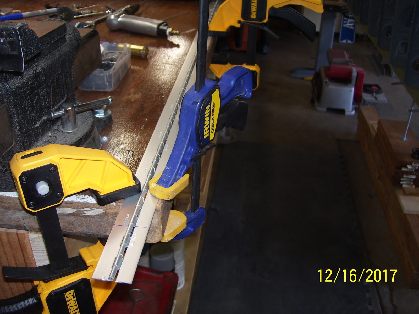
Here is how I clamped everything down to make the cuts:
One part that you also should fabricate, which the plans do NOT show, is another piece of .020 aluminum shaped to match the dimensions of the upper hinge half (about 1/2 of an inch wide). This is a spacer that allows the top half of the hinge to sit even with the bottom hinge and the door assembly, and allows the door to close as flush as possible next to the hole in the rib. Here is the hinge, the door, the spacer, and the hinge pin all cut to initial size.
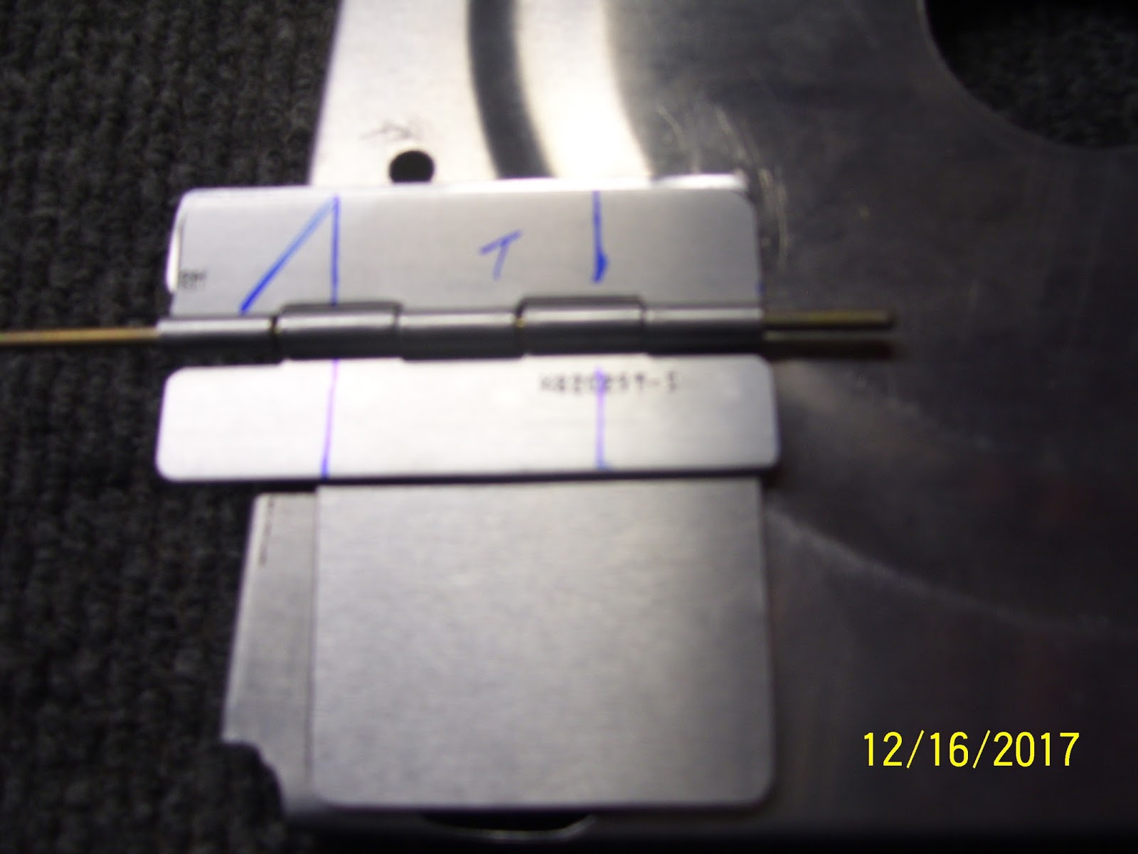
Next the hinge gets trimmed a bit more to match the width of the trap door and to form the upper hinge plate so that it has a small triangle on one end. More about that in a minute:
Here is my first trial fit of the assembly on the tank rib. I adjusted this a bit more later one, but this is the approximate location for the door, very near the rear rib flange:
After figuring out how to clamp the small hinge halves down on the bench so they could be trimmed to their final dimensions, I ended up with hinges that looked like this:
That little triangle on the top hinge half then gets bent 90 degrees to act as a door stop for the door. It cannot be allow to open all the way flush with the top side of the rib, because it may never close again, allowing any fuel that is currently in that first bay to escape into the outer baffles of the tank and away from the pickup line. So to prevent this, the little tab keeps the door from opening too far s that it cannot get stuck all the way open. To bend the tab, I put it in my vise like so:
Then I used a small rubber mallet to bend the metal 90 degrees. I had to position the tab properly in the vise so that the bend would occur in the proper place. the reality is that the tab needs to be a little bit inboard from the edge of the lower hinge and the door, to ensure that the door will always contact the stop and will not get stuck:
By this time I should also mention that I had already smoothed the edges of all parts on the scotch brite wheel and rounded all corners to avoid stress risers - standard deburring procedure. After the bend the parts looked like this:
Next came the painful task of marking rivet lines. I hated this part and it took a while before I was satisfied that I had the marks in the proper position. The plans do a horrible job of showing different pics with different hinge layouts that do not match each other, and they show that there should be 3 rivets on the top hinge and 3 on the bottom hinge. The only problem with this is that there is a huge stiffening ring you know - the one on the inboard rib that I cut with the fly cutter recently. So there is a huge void in the area where the upper center rivet is supposed to go (SO a rivet can't go there). And then the location of the top forward rivet is right on the edge of the rib web just on the other side of the stiffening ring, so getting the location of the rivet right is pretty important because the shop head and the hole both need to have enough room to seat properly.
Rivets for the bottom hinge can be evenly spaced as they all will fit on the rib web with no issues.To resolve this, I decided that the upper hinge could only have 2 rivets, and the bottom would have 3 rivets per the plans. The upper hinge would need rivet holes that are the right at the minimum edge distance of 3/16ths of an inch for an AN426AD3 rivet.The lower hinge rivet holes were spaced 1/4 inch from the edges, giving a little bit more of a buffer. Here are my early attempts to mark the rivet lines. found this to be very tricky because it was hard to get a straight edge on the hinges, because they are small to begin with, and the 5052 H34 aluminum alloy they are made with is very slippery. I remember dealing with this when I had to fab the trim tab hinge. It was a pain then and it is a pain now.
Since I had not had to bend hinge pins in a while, I could not remember how I did this in the past. So I decided to try to put a 90 degree bend in the hinge pin the same way I did the hinge. It did not work so well.
I ended up taking a small block of wood with a flat surface and placing it next to the pin and and then hitting the block of wood with the hammer - worked much better, the pin is much stiffer for obvious reasons, so it took a bit more force to get it to bend, but once it was started it went over pretty well.
Next was another trial fit to mark the final position of every thing after all the parts were final-formed. You leave a small opening at the bottom of the hole beause proseal sealant will be placed in this area of the rib flange, and you don't want the door to be so big that it interferes with the proseal. Also note that this hole goes all the way to the bottom of the bottom tank rib flange.Another funny thing that I saw from other folks build logs is that most folks put bends on the hinge pin on both sides of the pin, but some appeared to only put the bend on one end. Now, if yo put only one bend in the pin, and the bend is placed on the rear facing part of the hinge, that should be fine, assuming that the hinge pin is long enough to stay engaged in the hinge holes if it moves forward and backward, because the bend in the pin will eventually hit the rear rib web and baffle plate. However, I also saw some pics on some build logs where the bond was placed on the forward side of the hinge. IN this state there is NOTHING preventing the pin from falling out and causing potential blockages in the tank. I cold not believe this when I saw it. This pic shows the first bend toward the rear of the rib. I will be applying another bend on the other end when all final prep has been completed.
I decided to align the door with the rear rib flange a bit more. This should be the final position of my trap door. I have about 20 more pics of thos whole process, and if you haven't figured it out yet, this little assembly has taken quite a bit of time to research and fabricate. Most builders only show a finished pic of this door and say "here it is, already installed." Almost nobody provides the level of detail I am showing here. Hopefully this will help you with your build.
In the next post I will show how all the rivet holes were drilled and countersunk and hopefully complete the assembly of this seemingly simple little device.
KPR
Before I get into that whole story, I wanted to share some fun that I had with my wife a little over a week ago at a place near a local mall called canvas and cocktails. It is a place where you can go and paint something on canvas using water based acrylic paints, and have some alcohol while you do it. An instructor guides you through the process to paint the picture step by step, color by color, and brush by brush. I did this with my wife, my oldest son, and his girlfriend, and had an absolute blast. It "almost" made me brave enough to think that maybe I really can paint my own plane when the time comes. But let's not get into a rush on that just yet....
Here are our finished masterpieces - this particular painting had so many colors an shapes going on that it took longer than usual to finish it - almost 4 hours. But it was time well spent IMHO. Can you guess what it is, and which one do you think is mine or the wife's?
Now the trap door episode. What is it? Well, in aircraft where a flop tube is to be used for the fuel pickup line, and where possible extended unusual attitudes or 0 or negative G flight might be encountered, You have to ensure several things:
1. The engine has an inverted oil system
2. The fuel tank system is designed so that fuel can continue to be delivered to the engine at all times.
Vans standard design is to install a fixed, rigid fuel pickup line that stays in the same position in all flight attitudes all the time. I had decided when I ordered my wing kit to put one flop tube in the left wing and keep the standard fuel pickup tube in the right wing, with the idea that all unusual flight attitudes and inverted flight would be done with the left tank selected so that it takes advantage of the flop tube.
If you have ever built and flown gas or glow powered RC airplanes, you always had to put a heavy weighted clunk attached to a piece of fuel line inside the fuel tank. This allows gravity to keep the end of the fuel pick line inside the tank always accessing the lowest area where fuel resides. The flop tube is basically the same concept, made with some different materials and a few more fittings, but the exact same concept.
Another contraption that is also used to help ensure that fuel is always available and in close proximity to the flop tube is a so-called trap door, that is placed over a small hole in bottom rear of the next closest inboard tank rib. The most inboard rib obviously cannot contain any holes except those that contains a vent line or fuel feed lines that will route fuel to the engine from the wings and fuselage. However, all of the inboard ribs MUST contain openings that allow fuel to transfer from one bay between ribs to another bay. IN addition, the dihedral of the wings also forces fuel to continue to flow to the lowest inboard position in the wing tank, which is right over the corner where the fuel pickup line is located.
By the time the fuel gets to the last bay in the tank where it is picked up and routed to the engine, under normal flight attitudes and conditions it should generally remain in the last bay of the tank, closest to the fuselage. However, when performing aerobatics or high G maneuvers, it is possible that the fuel may attempt to move out of that first bay of the tank and back into the outer bays, away from the fuel pickup line. So to help prevent this, a small trap door is fabricated and installed on that first inner rib so that it covers the hole that allows fuel to enter that first bay in the tank. It is designed so that it opens and closes automatically as fuel pressure is exerted into or out of that bay. Any force that is applied that would allow fuel to be removed from that bay will also close the trap door, while pressure applied in the opposite direction forcing fuel into that bay will also open the trap door. There is no control linkage or motor or wires - it is just mounted with a hinge and a plate that is big enough to cover most of the opening in the rib, and is allowed to swing freely as described above.
Now for the funny part. It seems that my original reasons for wanting a flop tube in the tank may have been misguided somewhat.It turns out that the only time you really need the flop tube is if you intend to conduct sustained inverted or negative G flight. If you perform positive G maneuvers, which most aerobatics are, you don't really need the flop tube, and can get by with the standard fuel pickup line. Further more, if you keep the aircraft coordinated, fuel should always be available in the first bay of the tank, and never allow a condition where the pickup line or tube is un-ported. This then means that the trap door should also not normally be needed either.
Oh well, too late for that. Anyway I still like the idea of the trap door anyway as a bit of insurance to keep fuel in that first bay at all times. Turbulence can have a way of putting you in some very strange flight attitudes - ask me how I know....
So I decided to put in the trap door assembly since I am also going to use the flop tube. It starts with making the door itself from .020 inch thick aluminum from your trim bundle. This is thinner than a pop can and is the same thickness as the skin that was place on the rudder frame. I measured it per the plans and cut it from the sheet using left and right hand sheers. I think this was the frst time that I realize that the left and right designation does NOT apply to which hand you use to do the cutting, but rather the side of the cut that needs to be made and the amount of extra metal on either side of the cut that needs to be kept out of the way of the sheers and the cut. Never understood that, and never used these tools until now.
Next was figuring out where to get the hinge material from. the plans tell you what hinge to use, but they don't specify a part number of if this is supplied already with your wing kit. I learned from other builders that you can use a small section of the same hinge material for the wing flaps. these hinges are 6 feet long (72 inches), and a quick review of the flap assembly plans shows that only 56 inches is needed for the flaps, so they give you plenty of extra hinge material. I measured the length I needed per the plans, and marked the line. I used my Dremel cutoff wheel to cur the hinge, but I had to slide out the hinge pin first, because you need a little extra longer length of the hinge pin so you can bend the ends to keep the hinges from separating.
Here is how I clamped everything down to make the cuts:
One part that you also should fabricate, which the plans do NOT show, is another piece of .020 aluminum shaped to match the dimensions of the upper hinge half (about 1/2 of an inch wide). This is a spacer that allows the top half of the hinge to sit even with the bottom hinge and the door assembly, and allows the door to close as flush as possible next to the hole in the rib. Here is the hinge, the door, the spacer, and the hinge pin all cut to initial size.
Next the hinge gets trimmed a bit more to match the width of the trap door and to form the upper hinge plate so that it has a small triangle on one end. More about that in a minute:
Here is my first trial fit of the assembly on the tank rib. I adjusted this a bit more later one, but this is the approximate location for the door, very near the rear rib flange:
After figuring out how to clamp the small hinge halves down on the bench so they could be trimmed to their final dimensions, I ended up with hinges that looked like this:
That little triangle on the top hinge half then gets bent 90 degrees to act as a door stop for the door. It cannot be allow to open all the way flush with the top side of the rib, because it may never close again, allowing any fuel that is currently in that first bay to escape into the outer baffles of the tank and away from the pickup line. So to prevent this, the little tab keeps the door from opening too far s that it cannot get stuck all the way open. To bend the tab, I put it in my vise like so:
Then I used a small rubber mallet to bend the metal 90 degrees. I had to position the tab properly in the vise so that the bend would occur in the proper place. the reality is that the tab needs to be a little bit inboard from the edge of the lower hinge and the door, to ensure that the door will always contact the stop and will not get stuck:
By this time I should also mention that I had already smoothed the edges of all parts on the scotch brite wheel and rounded all corners to avoid stress risers - standard deburring procedure. After the bend the parts looked like this:
Next came the painful task of marking rivet lines. I hated this part and it took a while before I was satisfied that I had the marks in the proper position. The plans do a horrible job of showing different pics with different hinge layouts that do not match each other, and they show that there should be 3 rivets on the top hinge and 3 on the bottom hinge. The only problem with this is that there is a huge stiffening ring you know - the one on the inboard rib that I cut with the fly cutter recently. So there is a huge void in the area where the upper center rivet is supposed to go (SO a rivet can't go there). And then the location of the top forward rivet is right on the edge of the rib web just on the other side of the stiffening ring, so getting the location of the rivet right is pretty important because the shop head and the hole both need to have enough room to seat properly.
Rivets for the bottom hinge can be evenly spaced as they all will fit on the rib web with no issues.To resolve this, I decided that the upper hinge could only have 2 rivets, and the bottom would have 3 rivets per the plans. The upper hinge would need rivet holes that are the right at the minimum edge distance of 3/16ths of an inch for an AN426AD3 rivet.The lower hinge rivet holes were spaced 1/4 inch from the edges, giving a little bit more of a buffer. Here are my early attempts to mark the rivet lines. found this to be very tricky because it was hard to get a straight edge on the hinges, because they are small to begin with, and the 5052 H34 aluminum alloy they are made with is very slippery. I remember dealing with this when I had to fab the trim tab hinge. It was a pain then and it is a pain now.
Since I had not had to bend hinge pins in a while, I could not remember how I did this in the past. So I decided to try to put a 90 degree bend in the hinge pin the same way I did the hinge. It did not work so well.
I ended up taking a small block of wood with a flat surface and placing it next to the pin and and then hitting the block of wood with the hammer - worked much better, the pin is much stiffer for obvious reasons, so it took a bit more force to get it to bend, but once it was started it went over pretty well.
Next was another trial fit to mark the final position of every thing after all the parts were final-formed. You leave a small opening at the bottom of the hole beause proseal sealant will be placed in this area of the rib flange, and you don't want the door to be so big that it interferes with the proseal. Also note that this hole goes all the way to the bottom of the bottom tank rib flange.Another funny thing that I saw from other folks build logs is that most folks put bends on the hinge pin on both sides of the pin, but some appeared to only put the bend on one end. Now, if yo put only one bend in the pin, and the bend is placed on the rear facing part of the hinge, that should be fine, assuming that the hinge pin is long enough to stay engaged in the hinge holes if it moves forward and backward, because the bend in the pin will eventually hit the rear rib web and baffle plate. However, I also saw some pics on some build logs where the bond was placed on the forward side of the hinge. IN this state there is NOTHING preventing the pin from falling out and causing potential blockages in the tank. I cold not believe this when I saw it. This pic shows the first bend toward the rear of the rib. I will be applying another bend on the other end when all final prep has been completed.
I decided to align the door with the rear rib flange a bit more. This should be the final position of my trap door. I have about 20 more pics of thos whole process, and if you haven't figured it out yet, this little assembly has taken quite a bit of time to research and fabricate. Most builders only show a finished pic of this door and say "here it is, already installed." Almost nobody provides the level of detail I am showing here. Hopefully this will help you with your build.
In the next post I will show how all the rivet holes were drilled and countersunk and hopefully complete the assembly of this seemingly simple little device.
KPR
Labels:
Building Tips and Tricks,
Clamping,
Countersinking,
Cutting,
Deburring,
Fuel Tanks
Subscribe to:
Posts (Atom)