Tuesday, October 11, 2011

338 hours on the hobbs - Deburring, Countersinking, drilling, and so on....

No posts in the past few days because once again I have been busy out in the shop. Let's see now, Match drilled the tip rib, counter balance skin, front spar, and root rib of the right elevator to the skin, match drilled the control horn to the skin, deburred everything except for the skin and the spar, countersunk the AN426 rivet holes in the root rib and in the Lead counterweight, and dimpled the counter balance skin for the recessed screw heads of the mounting screws for the counterweight. In my "spare time" I got out my colored magic markers from Hobby Lobby, found my blank copies of the RV-8 3 view drawing provided in the plans, and started coloring to work out my paint scheme some more.

Oh yeah, and I also found time to run back and forth to HD to get the correct pneumatic connectors for my new sprinkler manifold that I had installed earlier this spring so I could blow out my sprinkler system, not that that has anything to do with building an airplane, except that I used the opportunity to drain the tank on my compressor, which did have a fair amount of water inside. I am saving the compressor oil change till after I finish riveting the elevators.

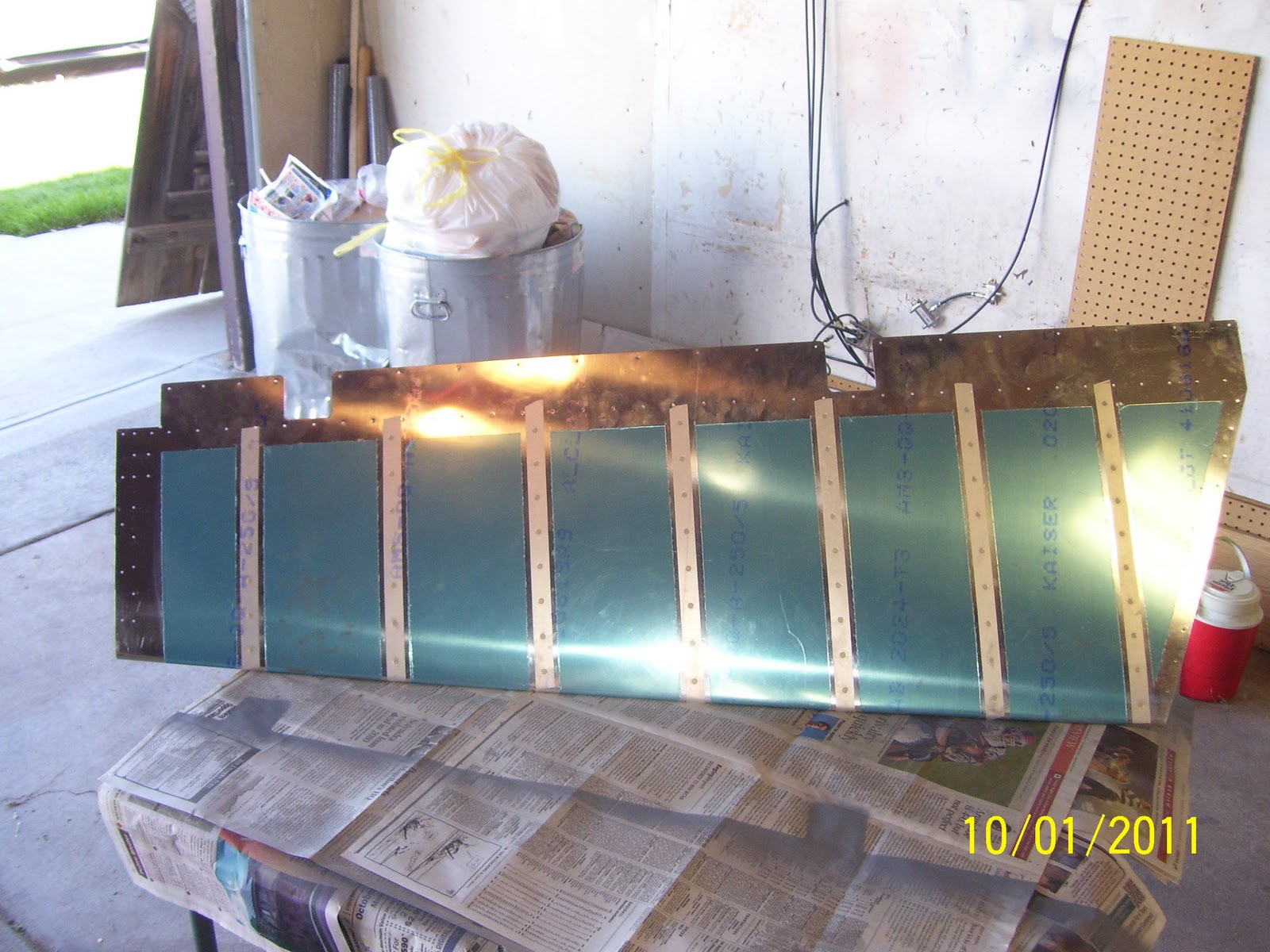
Not too many pics tonight - will take more tomorrow after I get a bit more prep work done. This is the time during every sub-assembly where you have to focus on all those holes in every single part, and it just seems to go on forever. So you keep plugging away until one day you finally get to pound some rivets. If all you had to do to build an airplane kit is slap the parts together and pound the rivets, this entire airplane would be done in about 6 months. The normal build time for most folks is between 3-5 years, so that tells you something about how much more time all the prep work adds to the process.

One tricky part of the build was countesinking a row of 4 AN426 rivet holes in the root rib. There is a flange on this rib that sits flush against the back side of the front spar, and this is the part of the elevator where the control horn then gets riveted into place over these other rivets holding the rib and spar together. So it needs to be very strong in this area to accept the forces that will be applied to the control horn when I move the stick back and forth to climb or descend as needed.

The rib flange is a bit awkard to work with in the conventional sense, due to the extreme bend in the flange that is necessary to create the angle in the elevator to allow enough clearance for the rudder to move back and forth. The rib flange is also a bit small to be able to put my countersink cage on. So I followed what Steve and other builders have done and used my deburring bit and my cordless drill/screw driver to gently countersink each of the 4 holes to accept the flush rivets that will strengthen this area. the Rivets need to be flush so that the control horn can be placed over the top of them. Again, pics will make this more clear. I just took my time and removed a small amount of material every couple of passes, adn then checked for symmetry of the countersunk hole, and also checked the depth by placing one of the rivets in the hole to determine when I had sunk everything deep enough.

Now for the cool part. My paint scheme is almost set. I just need to play around with the tail and nose spinner colors a bit. the core colors are pretty much decided, except for the actual shade of blue I will use. The following drawings are not too far from the pic I have inserted at the top of my blog. I have decided on a trim pattern after reviewing several paint schemes from photos of finished RVs. Below are two versions, one with a black front and the other with an olive drab front. I am probably going to stick with the black cuz I like that look a lot better.


And yes, before you eagle eyes out there start hammering me about the missing stripe on the wing of the first drawing and on the side of the second drawing, I am well aware of those issues! For those of you following my blog, send me a comment and tell me what you think. Remember you can click on the photos to get a larger version of the pic that will show much more detail. It was really fun to start to get an idea of what I want the finished project to look like. This ought to be an eye catcher for young eagles flights!

All for now.Getting close to pounding some rivets again!

Thursday, October 6, 2011

334 hours on the hobbs - Right Elevator Frame work in Progress

Had to flute and matchdrill the two tip ribs to themselves and to the front spar. This is the first time that I have dealt with two ribs that are butted up against each other. One of them is the tip rib for the end of the elevator, and the other is known as the counter balance rib. Then there is the counter balance skin and the counter balance lead weight. This is one really beefed-up area of the airplane, and I guess it needs to be given the forces that can be applied to this area during flight.

I also drilled out the two holes in the ribs and counterweight for the screws that will attach the weight to the ribs permanently. It's almost impossible to put it on a drill press to ensure a nice straight hole, so I had to free-hand drill this hole through the counter balance skin, the lead weight, and then through the rib flange on the other side, being as careful as possible to keep it straight. If the hole comes out the back side uncentered, the washer and nut may not ahve enough room to sit flat on the rib flange, and that means I would have to order new parts.

Here is the end rib adn the counter balance rib attached to the forward spar for match drilling:


And just in time for Halloween, this assembly looks more like a robot insect from a Tom Selleck Movie with Gene Simmons of KISS fame as the bad guy. I can't remember the name of the movie off hand but perhaps some of you will remember that movie.
And another shot - Here you see the lead weight nicely tucked inside the counter balance skin, up against the tip rib and the counter balance rib flanges. The counter balance rib is on the bottom and cannot be seen in this photo:


It was  a real bitch getting those clecos in place. If you did not take the time to properly flute the ribs and verify that the holes are lined up right it would be even worse, if not impossible to get the holes to line up. This assmebly is a very tight fit. I ended up with everything assembled as shown in the previous photo, and applied as much as force as necessary to get the rear-most holes in the rib to line up, effectively clecoing everything from the rear to the front where the weight is located. Once I got it started the rest of the holes seemed to line up pretty well.

And now for the dreaded hole drilling exercise. They give you two pilot holes to start with on the front of the counter balance skin. If you follow my blog you may remember that I had to prep another counter weight for the rudder not so long ago. The difference between that one and this one, other than the size and shape of the weight, is that the one for the rudder was pre-drilled, so you simply had to enlargen the existing hole a bit. For the elevators all you get is a solid piece of formed lead, and so you have to drill the entire hole through this stuff. You need to start with a lubricant and several drill sizes to step-drill the holes. I had to re-lube the bit often and also had to back out the bit by hand several times as the bit sinks into the lead and can almost imbed itself to the point where it will not move, or worse yet, may break off inside the lead. Luckily none of that happened. I just took my time and tried to drill slowly through the lead so I would not mess up. Note my clamp process as well. I needed to secure the entire assembly because backing the drill bit out took quite a bit of force (I used my Sioux air drill, which does not have a reverse mode on it). I used 3-in-1 oil for the lubricant and it worked just fine. I cleaned off the bits and re-lubed with each pass through the lead.

The plans call for drilling the holes to #12. To get there I started with a #40 and then stepped up using a #30, #28, # 21, #19, and finally the #12 bit. I may take this to a #10 since the screws are the same as the used for the rudder, just a bit longer, and I will need to countersink the lead and dimple the counter balance skin for the screww heads to sit flush with the skin so that they do not interfere with the tip of the horizontal stab after they are assembled.

Monday, October 3, 2011

A new addition to the family

This post is not much to do wtih airplanes, but I thought I would take a moment to introduce the newest member of our family. Her name is Molly. My wife had been visiting the local animal shelter for several weeks and called me up a couple of weeks ago to go take a look at "really nice dog." So I went down, and lo and behold a few days later, we have a new pet. She has turned out to be a fantastic dog and we are blessed to have found her.

330 hours on the Hobbs - Right Elevator in progress

I haven't been posting much lately cuz I have been busy working on the plane, (and the fence, and the new dog, etc., etc. More on the dog in a moment. I got past the dimple screw up on the elvator skin and moved on. Here is the right elevator skin dimpled and scuffed for primer:

And here are the rivets being taped into place for back riveting, same pocess as was done on the rudder.
And one side rivets all taped in and ready to go

And here is the knee-buster back rivet setup again - just like was done for the rudder:

My friend, neighbor, co-worker, and fellow pilot/flight instructor Kevin Shepard came by on Saturday morning to help me back rivet the stiffeners onto the rudder. They turned out great as shown in the next pic. THANKS KEVIN!!


That was actually quite the task. I had intended on priming everything on Friday evening so that all we had to do was rivet everything on Saturday morning. Well, as it turns out, my other friend ad fellow builder Mike Rettig called me up nad said they were having a movie night. Since the wife and kids had gone to Canon City to visit her parents, I was all alone, and decided to go see a movie. Mike had a really great setup outside on his deck, with a projector and home made screen hanging from his deck posts - friends and neighbors, popcorn and beer, food, and a great movie. What a great time. Anyway, that meant that I had to do everything on Saturday morning as I told Kevin to meet me at 10:00am.

So I was up at the crack of dawn and dawned my respirator and got everything primed in time for Kevin to help me do the riveting.

So with the back riveting done, it was time to bend the trailing edge. This happened on Sunday afternoon after I conned Mike into driving out to help me with the bend. It took us all of about 15 minutes to do the bend, and this was at about 3:00 pm in the afternoon. Then we started talking airplanes and he ended up leaving around 7:00pm. I think he needs to bend his elevators on the RV 10 so I thought he might get some insight as to the process. THANKS MIKE.


This is the outside rib and counter-balance skin assembly for the right elevator, clecoed into place. At this point I was setting the frame in place to get a rough idea of how well the bend had worked out. I had noted after Mike and I were finished that it seemed a bit bulgy in the middle, and I thought I might need to bend it just a little more, but I decided to sleep on it for a bit.
And this is the inboard side, or the side closest to the fuselage side, showing the rib that goes there. As it turns out, As soon as I pulled the vinyl off of the rib, I found nice deep scratch right down the middle of the rib web. I will get Vans to replace this part - even if the scratch only goes no deeper than the alclad, this is a part that I do not want to mess around with. I need total integrity here as this will be a major point of applied force when the stick is moved to raise or lower the elevators.

This last shot shows that the final radius for the elevator is about 1/8 of an inch, same as the rudder. THis pic also shows that the edge is still a bit fat. So I did decide to bend the edge jsut a bit more this evening, and I think I have just about right. Funny how I spent weeks researching this for weeks for the rudder, and now it just does not seem to be that big of a deal. As long as you have a nice straight piece of wood for your bending break, and you ensure that the edge remains consistent across the span of the wood, i.e. one side of the edge is not displaced or angled from the edge of the break more than the other side (edge is not aligned with the edge of the brake), then everything comes out fine.

One more note about the weekend activities. My other friend and builder Ron Duren invited me to a barbeque on Saturday night. He has blown me right out of the water with his progress on his RV - 7. The Tail and wings are done, and the fuselage is in progress. He now has very big pieces of the airplane in his garage. I can't wait until I reach the same point. I took a bunch of pics of his build, and will post some of them later. Another night of great food, great friends, and great times. Ron will obviously be flying well before I am, and I am truly indebted to hime for all his past assistance, and for being the guinnie pig for blazing the airplane building trail that I am able to follow, learning from his mistakes and from his wisdom along the way. THANKS FOR A GREAT TIME RON!

Next for me is the prep of the spar and ribs for the right elevator, and then assembling it. then comes the dreaded left elevator and trim tab assembly. With my chosen implementation, I don't think that the trim tab will be a problem for me.

Tuesday, September 20, 2011

321 hours on the hobbs - Fixing the right elevator skin problem

Work sucked up all my time this past week, and I had to renew my CFI ticket by finishing an online course (that did not suck so much, but still took a lot of time). I was finally able to get back to the elevator again tonight.

After posting my latest screw up on VAF and becoming immortalized on the Aircraft - Specific link for the RV-8, and then on the front page of VAF with a "Dang it" caption from Doug Reeves, it was time to make a decision as to the solution to my dimple screw up on the elevator skin. I had several replies from differnt folks as to the best way to fix this problem. I decided to go ahead and do the following:

1. Stop-drilled the crack, which basically means that I had to drill out the hole that I had tried so hard to plug back up. As the following pics will show, now it is truly a figure 8 set of holes, but they will be filled prior to painting, and will not be visible once the paint gets applied.

This is a standard procedure to relieve stress build ups in areas where cracking occurs, and it applies to cracks in metal as well as cracks in other materials such as fiberglass, plexiglass, etc. The procedure us relatively straight forward - find the end of the crack in progress, drill a hole just slightly beyond the very end of the crack to allow the crack to migrate to, and stop it from cracking any further.

2. Flatten the dimple in the intended hole, and also in the matching hole in the stiffener, to provide as much support in the area now that I will be essentially bypassing it. I used the flat set in my rivet gun and the back rivet plate to flatten the dimples just as I did before. All it takes is a couple of light taps from the rivet gun and you are done.

3. Measure, mark, and drill 2 new holes, one on either side of the intended hole and the stop-drilled hole right next to it. These 2 new holes will provide two new contact points with 2 new rivets added to provide support for the area on the skin that was compromised with the unintended hole that was created when the skin slipped off the dimple die. I added the two new holes about half way between the intended hole and the holes on either side of that one. trying to keep the nice neat rivet line is the challenge here. We'll see how it looks after the stiffeners are back riveted onto the skin.

4. Cleco the stiffener onto the skin, and use the new holes in the skin as drill guides to finish match drilling the new holes into the stiffener

5. Remove the stiffener, debur the new holes in the skin and stiffener, and dimple them. This time I made certain that the skin did NOT slip off of the dimple die.

And here are the pics of the process. First one is after removing the existing dimples, and marking and drilling the new holes. Notice the figure 8 where I had to stop drill the botched hole in order to keep it from cracking. Click on the pic to get a larger more clear view of this. The new holes are also drilled adn visible:


And another one from the top side of the skin:

And finally a slightly blurry close up of the two holes that are now going to have to be filled. You can still see the crack that used to be along the edge of the dimple, which has now been flattened back out. UNfortunately this will be an eyesore until everything is filled and painted, since it is on the top of the elevator skin. Several folks have told me that as long as I have done this repair, I will never see a crack in this area again once everything is filled and painted. Worse case scenario is that I get to make a new elevator somewhere down the line, and maybe that is not such as bad thing either.

Sunday, September 11, 2011

A note about the 10th Anniversary of 9/11

All I wish to say is simply this......

I am an American, and I am damn proud of that fact.
I have taken some time today to reflect on the events that occurred 10 years ago, and I hope that each of you managed to take at least a little time to do so as well.

During that time of reflection, something happened to me that I thought I would share:

As the thoughts of the 9/11 anniversary suddenly overtook me, my attention immediately turned toward the sky. I noticed that it was not "silent" as it was 10 years ago, when all aviation was grounded on that terrible day. Many contrails filled the sky from high flying jets, and the sounds of airplanes filled the air all around me - again, completely unlike that dreadful day 10 years ago.

It put a smile on my face to see and hear aviation happening all around me.

Peace and hope to all who protect this great country, and to those of us that are so blessed to live here...

314 hours on the hobbs, Finish the Rudder and Let the elevators rise!!!!!

....Some final thoughts on the rudder. Just a couple more pics to show the details of the temporary hinge pin that I had to forcefully remove in order to separate the VS and rudder as described in my previous post. See the etched marks where the 1/2 inch cold chisel was placed to try to hammer out the pin from the hinge. Nice thing to have to do to something attached your aluminum airplane, huh!


The marks on the curved part are where the cold chisel was place. The marks on the top part were made by the hinge as I tried to pound this little sucker out.

Next is the tip of the temporary hinge that I had to cut off with the dremel tool. Not a real good pic, but if you look closely, you can see the ridge that had built up on the end, right next to the hinge plate, which is why I could not remove it easily. Thanks a gain Van's for not elaborating on the need to drill out the hinges to final size. (Still pissed off about that!)


And lastly, a set of new temporary hinges from Aircraft Spruce (Actually made by Avery tools). I ordered these fr several reasons: They have the threaded end on one end along with a threaded holder for ease of placement/removal, and they are short enough to allow for full control surface travel one placed in the hinge. They don't have that stupid long extension that gets in the way. The threaded holder allows me to get leverage on the hinge via the screw threads instead of having to pound it out with a hammer. Of course, now that I know I need to finish drill all the hinge holes to the correct size, I don't expect to ever have a problem with this again.


Now on to brighter things - -no more rudder for a while -  on to the elevators, which make the plane go up and down......

The process is very much like building the rudder. Starts with stiffeners as the main support element for the elevator skins. Here is my little work table setup that I clamped to the work bench. I decided to trim the stiffeners outside this time to keep from messing up my inside workroom work benches. Thankfully the elevators are a bit smallers in all dimensions from the rudder, so all the structural pieces are a bit smaller as well. I clamped a small piece of partical board to the the end of the workbench to allow several edges to place the angle for the stiffeners depending the cut I needed to make, and used my dremel tool with a extension shaft that I got for christmas to provide a bit more control while trimming the stiffeners.


I use two different types of REINFORCED cutoff wheels. If you use a dremel tool, and I can't for the life of understand how you will be able to finish a kit like this without one, do NOT use the small flimsy non-reinforced wheels that typically will come with a standard dremel tool kit. Use the larger, reinforced ones, adn remember to where ear adn eye protection when you trim the stiffeners from the angle. Why use  dremel instead of the shears as Van;s suggests? Because the shears leave serrated edge on the metal and are not well suited fortrimming smaller parts. The edge has to be filed down to remove any stress risers, whereas the dremel cut is much easier to cleanup with the Scotch Brite wheel.


And a shot of pretty much all the equipment to get the job done. Be sure to buy the economy pack up cutoff wheels - you will run through many of them:

A shot of the rough cut stiffeners after using the dremel tool to trim them to initial shape. Edges are very sharp and jagged at this point, so be very careful handling these pieces..

Note that I always leave some excess from the cutline on purpose so that I can bring then down to final shape using the scotch brite wheel, which is much easier to control. I also take the time to get the tail end each stiffener small enough so that when the elevator is bent the edges of the stiffeners will not interfere with the skin.


Thes next three pics are of yet another screw up that may actually cost me a new right elevator skin. I had cleanup the stiffeners and dimpled them, and was then in the process of dimpling the right elevator skin. I thought I had developed a sure fire method to prevent pounding a dimple hole in an unwanted place on the skin, but I managed to find a way around it.... THe pics that follow are what is know to us builders as the dreaded figure 8 dimple, because that is what it looks like when you screw it up. The new hole is close to the actual hole and this creates the figure 8 effect. IN my case, I tried to smooth out the bad one with my flush set, which worked pretty well, but then I tried to dimple the original hole and ended up with a crack that I now have to resolve somehow. I have posted the pics to VAF to get some opinions as to the best method to try to finx this. Hopefully I won't need a new skin. The first two are on the underside of the skin, and the last pic is looking at it from the outside. Can't let this crack go unattended or it will surely continue to crack later on...

As a well known participant on Van's Air Force forums always says, "It's just one damn thing after another...."


Oh, and to finish up - went on the annual dove hunt with my youngest son and my neighbor, a fellow CFII and coworker. We caught a couple of pics of some awesome sunrises out there that I thought I would share. This is out in Northeastern Colorado in farm and cow country. I can't wait to see some more of these types of scenic views from the air. Hope you enjoy them.