After the flycutter episode with the most inboard fuel tank rib, the next feat was to fabricate something known as the trap door on the inboard rib that sits next to the most inboard tank rib. So this is now becoming a process of removing the ribs from the skin to prepare for the final assembly of the fuel tank.
Before I get into that whole story, I wanted to share some fun that I had with my wife a little over a week ago at a place near a local mall called canvas and cocktails. It is a place where you can go and paint something on canvas using water based acrylic paints, and have some alcohol while you do it. An instructor guides you through the process to paint the picture step by step, color by color, and brush by brush. I did this with my wife, my oldest son, and his girlfriend, and had an absolute blast. It "almost" made me brave enough to think that maybe I really can paint my own plane when the time comes. But let's not get into a rush on that just yet....
Here are our finished masterpieces - this particular painting had so many colors an shapes going on that it took longer than usual to finish it - almost 4 hours. But it was time well spent IMHO. Can you guess what it is, and which one do you think is mine or the wife's?
Now the trap door episode. What is it? Well, in aircraft where a flop tube is to be used for the fuel pickup line, and where possible extended unusual attitudes or 0 or negative G flight might be encountered, You have to ensure several things:
1. The engine has an inverted oil system
2. The fuel tank system is designed so that fuel can continue to be delivered to the engine at all times.
Vans standard design is to install a fixed, rigid fuel pickup line that stays in the same position in all flight attitudes all the time. I had decided when I ordered my wing kit to put one flop tube in the left wing and keep the standard fuel pickup tube in the right wing, with the idea that all unusual flight attitudes and inverted flight would be done with the left tank selected so that it takes advantage of the flop tube.
If you have ever built and flown gas or glow powered RC airplanes, you always had to put a heavy weighted clunk attached to a piece of fuel line inside the fuel tank. This allows gravity to keep the end of the fuel pick line inside the tank always accessing the lowest area where fuel resides. The flop tube is basically the same concept, made with some different materials and a few more fittings, but the exact same concept.
Another contraption that is also used to help ensure that fuel is always available and in close proximity to the flop tube is a so-called trap door, that is placed over a small hole in bottom rear of the next closest inboard tank rib. The most inboard rib obviously cannot contain any holes except those that contains a vent line or fuel feed lines that will route fuel to the engine from the wings and fuselage. However, all of the inboard ribs MUST contain openings that allow fuel to transfer from one bay between ribs to another bay. IN addition, the dihedral of the wings also forces fuel to continue to flow to the lowest inboard position in the wing tank, which is right over the corner where the fuel pickup line is located.
By the time the fuel gets to the last bay in the tank where it is picked up and routed to the engine, under normal flight attitudes and conditions it should generally remain in the last bay of the tank, closest to the fuselage. However, when performing aerobatics or high G maneuvers, it is possible that the fuel may attempt to move out of that first bay of the tank and back into the outer bays, away from the fuel pickup line. So to help prevent this, a small trap door is fabricated and installed on that first inner rib so that it covers the hole that allows fuel to enter that first bay in the tank. It is designed so that it opens and closes automatically as fuel pressure is exerted into or out of that bay. Any force that is applied that would allow fuel to be removed from that bay will also close the trap door, while pressure applied in the opposite direction forcing fuel into that bay will also open the trap door. There is no control linkage or motor or wires - it is just mounted with a hinge and a plate that is big enough to cover most of the opening in the rib, and is allowed to swing freely as described above.
Now for the funny part. It seems that my original reasons for wanting a flop tube in the tank may have been misguided somewhat.It turns out that the only time you really need the flop tube is if you intend to conduct sustained inverted or negative G flight. If you perform positive G maneuvers, which most aerobatics are, you don't really need the flop tube, and can get by with the standard fuel pickup line. Further more, if you keep the aircraft coordinated, fuel should always be available in the first bay of the tank, and never allow a condition where the pickup line or tube is un-ported. This then means that the trap door should also not normally be needed either.
Oh well, too late for that. Anyway I still like the idea of the trap door anyway as a bit of insurance to keep fuel in that first bay at all times. Turbulence can have a way of putting you in some very strange flight attitudes - ask me how I know....
So I decided to put in the trap door assembly since I am also going to use the flop tube. It starts with making the door itself from .020 inch thick aluminum from your trim bundle. This is thinner than a pop can and is the same thickness as the skin that was place on the rudder frame. I measured it per the plans and cut it from the sheet using left and right hand sheers. I think this was the frst time that I realize that the left and right designation does NOT apply to which hand you use to do the cutting, but rather the side of the cut that needs to be made and the amount of extra metal on either side of the cut that needs to be kept out of the way of the sheers and the cut. Never understood that, and never used these tools until now.
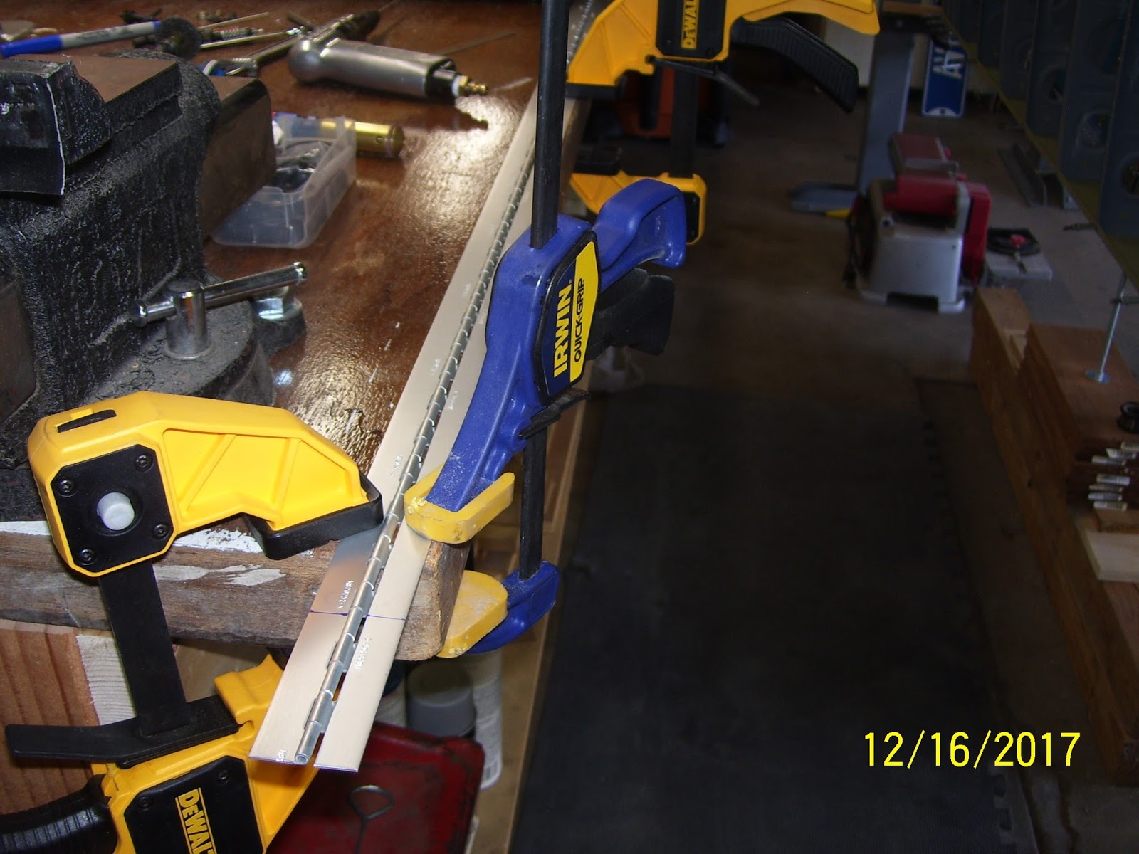
Next was figuring out where to get the hinge material from. the plans tell you what hinge to use, but they don't specify a part number of if this is supplied already with your wing kit. I learned from other builders that you can use a small section of the same hinge material for the wing flaps. these hinges are 6 feet long (72 inches), and a quick review of the flap assembly plans shows that only 56 inches is needed for the flaps, so they give you plenty of extra hinge material. I measured the length I needed per the plans, and marked the line. I used my Dremel cutoff wheel to cur the hinge, but I had to slide out the hinge pin first, because you need a little extra longer length of the hinge pin so you can bend the ends to keep the hinges from separating.
Here is how I clamped everything down to make the cuts:
One part that you also should fabricate, which the plans do NOT show, is another piece of .020 aluminum shaped to match the dimensions of the upper hinge half (about 1/2 of an inch wide). This is a spacer that allows the top half of the hinge to sit even with the bottom hinge and the door assembly, and allows the door to close as flush as possible next to the hole in the rib. Here is the hinge, the door, the spacer, and the hinge pin all cut to initial size.
Next the hinge gets trimmed a bit more to match the width of the trap door and to form the upper hinge plate so that it has a small triangle on one end. More about that in a minute:
Here is my first trial fit of the assembly on the tank rib. I adjusted this a bit more later one, but this is the approximate location for the door, very near the rear rib flange:
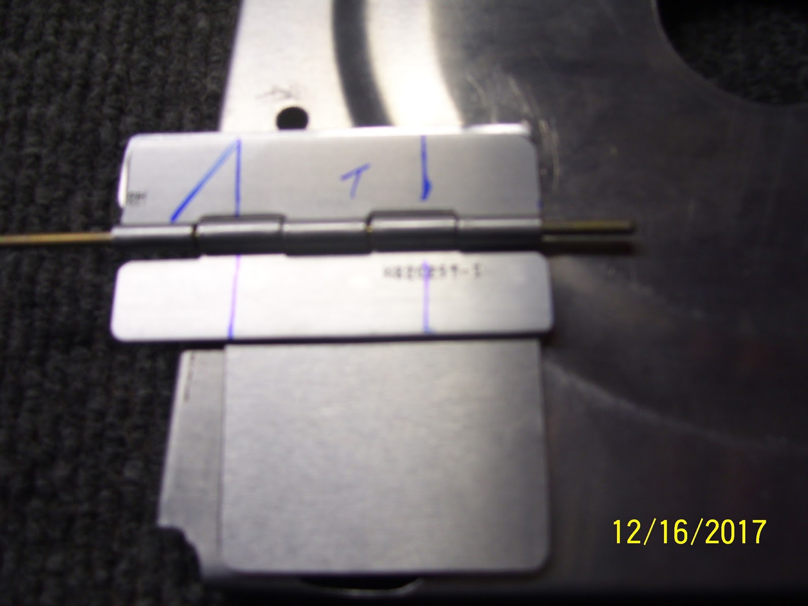
After figuring out how to clamp the small hinge halves down on the bench so they could be trimmed to their final dimensions, I ended up with hinges that looked like this:
That little triangle on the top hinge half then gets bent 90 degrees to act as a door stop for the door. It cannot be allow to open all the way flush with the top side of the rib, because it may never close again, allowing any fuel that is currently in that first bay to escape into the outer baffles of the tank and away from the pickup line. So to prevent this, the little tab keeps the door from opening too far s that it cannot get stuck all the way open. To bend the tab, I put it in my vise like so:
Then I used a small rubber mallet to bend the metal 90 degrees. I had to position the tab properly in the vise so that the bend would occur in the proper place. the reality is that the tab needs to be a little bit inboard from the edge of the lower hinge and the door, to ensure that the door will always contact the stop and will not get stuck:
By this time I should also mention that I had already smoothed the edges of all parts on the scotch brite wheel and rounded all corners to avoid stress risers - standard deburring procedure. After the bend the parts looked like this:
Next came the painful task of marking rivet lines. I hated this part and it took a while before I was satisfied that I had the marks in the proper position. The plans do a horrible job of showing different pics with different hinge layouts that do not match each other, and they show that there should be 3 rivets on the top hinge and 3 on the bottom hinge. The only problem with this is that there is a huge stiffening ring you know - the one on the inboard rib that I cut with the fly cutter recently. So there is a huge void in the area where the upper center rivet is supposed to go (SO a rivet can't go there). And then the location of the top forward rivet is right on the edge of the rib web just on the other side of the stiffening ring, so getting the location of the rivet right is pretty important because the shop head and the hole both need to have enough room to seat properly.
Rivets for the bottom hinge can be evenly spaced as they all will fit on the rib web with no issues.To resolve this, I decided that the upper hinge could only have 2 rivets, and the bottom would have 3 rivets per the plans. The upper hinge would need rivet holes that are the right at the minimum edge distance of 3/16ths of an inch for an AN426AD3 rivet.The lower hinge rivet holes were spaced 1/4 inch from the edges, giving a little bit more of a buffer. Here are my early attempts to mark the rivet lines. found this to be very tricky because it was hard to get a straight edge on the hinges, because they are small to begin with, and the 5052 H34 aluminum alloy they are made with is very slippery. I remember dealing with this when I had to fab the trim tab hinge. It was a pain then and it is a pain now.
Since I had not had to bend hinge pins in a while, I could not remember how I did this in the past. So I decided to try to put a 90 degree bend in the hinge pin the same way I did the hinge. It did not work so well.
I ended up taking a small block of wood with a flat surface and placing it next to the pin and and then hitting the block of wood with the hammer - worked much better, the pin is much stiffer for obvious reasons, so it took a bit more force to get it to bend, but once it was started it went over pretty well.
Next was another trial fit to mark the final position of every thing after all the parts were final-formed. You leave a small opening at the bottom of the hole beause proseal sealant will be placed in this area of the rib flange, and you don't want the door to be so big that it interferes with the proseal. Also note that this hole goes all the way to the bottom of the bottom tank rib flange.Another funny thing that I saw from other folks build logs is that most folks put bends on the hinge pin on both sides of the pin, but some appeared to only put the bend on one end. Now, if yo put only one bend in the pin, and the bend is placed on the rear facing part of the hinge, that should be fine, assuming that the hinge pin is long enough to stay engaged in the hinge holes if it moves forward and backward, because the bend in the pin will eventually hit the rear rib web and baffle plate. However, I also saw some pics on some build logs where the bond was placed on the forward side of the hinge. IN this state there is NOTHING preventing the pin from falling out and causing potential blockages in the tank. I cold not believe this when I saw it. This pic shows the first bend toward the rear of the rib. I will be applying another bend on the other end when all final prep has been completed.
I decided to align the door with the rear rib flange a bit more. This should be the final position of my trap door. I have about 20 more pics of thos whole process, and if you haven't figured it out yet, this little assembly has taken quite a bit of time to research and fabricate. Most builders only show a finished pic of this door and say "here it is, already installed." Almost nobody provides the level of detail I am showing here. Hopefully this will help you with your build.
In the next post I will show how all the rivet holes were drilled and countersunk and hopefully complete the assembly of this seemingly simple little device.
KPR
Thursday, December 21, 2017
Saturday, December 16, 2017
Using a Fly Cutter for the Very First Time
I purchased this tool a long time ago, expecting that I would need to use it sooner or later. My initial expectation was that I would be using it to cut round holes for certain instruments on the instrument panel. I did NOT expect that I would need to use it on my fuel tank.
Basically, I needed to cut out the entire section of metal on the inboard fuel tank rib s that an access plate can be installed to allow servicing of the fuel tank in that area, should the need ever arise. Since I decided NOT to install the capacitive sender kit from Vans per their recommendation, and I am now going to switch to the normal float sender instead, the access plate would also normally contain the mounting flange for float sender, as well as the AN 833 hardware for the fuel pickup line fitting, that takes fuel from the pickup line and routes it through an elbow joint through the access plate.This will be how things get assembled for the right fuel tank, as it will be a stock tank per the plans for the most part.
The left tank, on the other hand, does not contain the stock fuel pickup line, but instead will use a flop tube as I have described previously. In addition, since I am still using the flop tube in the left tank, I cannot install the float sender in it's intended original position, as it will interfere with it. SO I will need to put the float sender in the next bay over, and mount it to the rear baffle instead of on the access plate on the T-703 tank rib web.
Aside from all that, I still need to install the access panel on the rib web, but instead of using the T-708 plate on the left tank, I will use the other solid plate that came with the capacitive sender kit. the pics will show this more clearly later. Anyway, before I even get to that, I have to cut a very large hole, so large in fact that it is too big for hole saw, and for a spade bit or other type of drill bit. the Fly wheel cutter tool was specifically designed for this situation.
The plate gets prosealed and screwed onto the rib web so that you can access from the wing after removing the wing fairing. Although it is a tight space, you are supposed to be able to remove this plate and service the tank in certain ways without the need to remove the tank from the wing. A reinforcement ring goes on the other side of the rib web and serves as the mounting bracket for the access plate. Here is a pic of that bracket with the T-410 stiffeners precut in side of it. I used snips to separate the small tangs holding each part together, and then used a small file to grind down the remaining slag. Later I found out that you can pretty much just lightly twist these parts and they will separate. am always cautious about this sort of thing from my plastic model building days, since twisting the parts of the tree would sometime remove portions of the actual part. SO you learned to use snips or clippers to keep from damaging the plastic parts.On the right is the parts removed from each other, adnon the left is the part for the right fuel tank with everything still attached as it came from the factory:
The plans do not mention how big the hole needs to be, just that you need to make one (another Vans instruction feaut-pa). So after researching some builders sites I realized that the hole needs to match the opening in the reinforcement bracket shown above - duh! So this was as easy as placing the bracket over the stiffening ring on the aft end of the rib web, and tracing the inner circle onto the web:
Next came the "art" of placing a drill board on the drill press table, followed by the rib, and then figuring out how to clamp everything down solid.I also needed to find the precise diameter and then the radius of the circle. It turned out to be a 5.25 inch diameter, with a 2 and 5/8 inch radius on each side of the center. I needed to mount the fly wheel cutter into the drill press chuck as shown, so that I could mark the center for the drill bit:
The very next thing you need to do is setup the belts on your drill press, or reduce your speed adjustment to achieve the absolute lowest RPM that you can achieve with your drill press. With mine being a standard large floor model press, I was able to adjust the belts to get it down to 250 RPM.
Next was the task of setting up the cutter as precisely as possible for the radius. Safety point - the point on end of the cutter is EXTREMELY sharp - do not mess around with this - keep your fingers clear of it at all times, and keep the drill press unplugged until you are ready to use it, and all adjustments have been completed.The tool comes with a set of Allen head screws to adjust the radius of the cutter from the center of the pilot bit, which is a 1/4 inch drill bit. IN addition, a second Allen screw is used to adjust the depth of the cutter compared to the depth of the pilot bit. The instructions say to set the cutter depth 1/4 inch higher than the tip of the pilot bit - the idea being that the pilot bit drills the hole in the center to provide a stable grip for the cutter to retain the set radius without wandering. A drill board underneath the part to be cut is also ESSENTIAL for this to work properly.
Another Safety tip: When the cutter makes contact with the metal, it emits a very loud and uncomfortable squeal. it sounds kind of like when a kid scrapes his finger nails across a blackboard - yup - it's just about that bad. So, I highly recommend that you wear ear muffs during this operation as well as safety glasses and leather gloves.
With everything positioned correctly, and the worked clamped down properly, you then dawn some thick heavy work gloves and keep all hands clear of the work piece until the drill is stopped. You start bringing the pilot bit down until it engages, and then you SLOWLY apply more pressure on the press to keep bringing the cutting bit down onto the metal. Check the cut as it engages and make sure that it does not wander from the marks that you had drawn earlier.If the part moves, or worse yet, if it becomes hung, make sure you stay out of harms way and then pull the plug on the drill press to stop it. Do NOT try to rescue the part from its demise. This is where this tool is absolutely dangerous. It can take a piece of metal and turn it into a disemboweling razor knife in a split second, and then it can take that piece of deadly metal and fling it directly at you, which is why you need to keep the drill press at the lowest possible RPM.
Make no mistake, this thing can KILL you in an instant if things start to go awry. So pay attention and take every possible safety precaution before starting the process.
If everything goes according to plan, eventually the cutter will go all the way through the metal, and you can stop the drill press. Then UNPLUG the drill press from the wall. Then and only then should you reach in with gloved hands and remove the part. Here is the new hole in the rib after the operation was complete. Notice the shavings that it creates as it cuts:
That circular piece of metal has a razor edge on it since part of the cut was made against the curvature of the stiffening ring. You could slice meat with it - or your fingers, so again, be careful when you handle this thing.
Next is a pic of the rib with its new hole, with the reinforcement bracket positioned over it, both types of access cover plates, with and without the sender and fuel pickup line hardware holes, and a cork gasket.
A couple more things I learned from my research and several phone calls to Vans - throw the cork gasket away and DO NOT USE IT - PERIOD! Over time the gasket becomes saturated with fuel and WILL START LEAKING - so NO CORK GASKET! I also learned that the mounting flange of the fuel float sender unit has a rubber gasket that you also SHOULD NOT USE, as it starts leaking as well. As I stated earlier, my left tank will use the plate on the left, and my right tank will use the standard plate on the right.
SO that is how you setup and use a fly wheel cutter tool in a drill press to cut very large, precise holes in metal. Now I just have to debur the edges of the rib a bit and continue with the remaining fuel tank assembly tasks.
On another note, There is also a trap door with a hinge on it that I need to fabricate. TO do so, Vans told me that I needed to use the hinge material from the flap hinges that came with the wing kit. Since these hinges were 6 feet long, I had stored them up on my wide garage shelf with the other long parts like the angles used for the longerons for the fuselage that are 15 feet long. The problem was that I had to get to them on the shelf, which was not exactly "easy." I had to move a bunch of stuff off the shelf first in order to get to the hinges. I finally got them down, and spent a large part of today, cleaning up the garage and putting everything back in its place.
More on the trap door fabrication tomorrow.
KPR.
Basically, I needed to cut out the entire section of metal on the inboard fuel tank rib s that an access plate can be installed to allow servicing of the fuel tank in that area, should the need ever arise. Since I decided NOT to install the capacitive sender kit from Vans per their recommendation, and I am now going to switch to the normal float sender instead, the access plate would also normally contain the mounting flange for float sender, as well as the AN 833 hardware for the fuel pickup line fitting, that takes fuel from the pickup line and routes it through an elbow joint through the access plate.This will be how things get assembled for the right fuel tank, as it will be a stock tank per the plans for the most part.
The left tank, on the other hand, does not contain the stock fuel pickup line, but instead will use a flop tube as I have described previously. In addition, since I am still using the flop tube in the left tank, I cannot install the float sender in it's intended original position, as it will interfere with it. SO I will need to put the float sender in the next bay over, and mount it to the rear baffle instead of on the access plate on the T-703 tank rib web.
Aside from all that, I still need to install the access panel on the rib web, but instead of using the T-708 plate on the left tank, I will use the other solid plate that came with the capacitive sender kit. the pics will show this more clearly later. Anyway, before I even get to that, I have to cut a very large hole, so large in fact that it is too big for hole saw, and for a spade bit or other type of drill bit. the Fly wheel cutter tool was specifically designed for this situation.
The plate gets prosealed and screwed onto the rib web so that you can access from the wing after removing the wing fairing. Although it is a tight space, you are supposed to be able to remove this plate and service the tank in certain ways without the need to remove the tank from the wing. A reinforcement ring goes on the other side of the rib web and serves as the mounting bracket for the access plate. Here is a pic of that bracket with the T-410 stiffeners precut in side of it. I used snips to separate the small tangs holding each part together, and then used a small file to grind down the remaining slag. Later I found out that you can pretty much just lightly twist these parts and they will separate. am always cautious about this sort of thing from my plastic model building days, since twisting the parts of the tree would sometime remove portions of the actual part. SO you learned to use snips or clippers to keep from damaging the plastic parts.On the right is the parts removed from each other, adnon the left is the part for the right fuel tank with everything still attached as it came from the factory:
The plans do not mention how big the hole needs to be, just that you need to make one (another Vans instruction feaut-pa). So after researching some builders sites I realized that the hole needs to match the opening in the reinforcement bracket shown above - duh! So this was as easy as placing the bracket over the stiffening ring on the aft end of the rib web, and tracing the inner circle onto the web:
Next came the "art" of placing a drill board on the drill press table, followed by the rib, and then figuring out how to clamp everything down solid.I also needed to find the precise diameter and then the radius of the circle. It turned out to be a 5.25 inch diameter, with a 2 and 5/8 inch radius on each side of the center. I needed to mount the fly wheel cutter into the drill press chuck as shown, so that I could mark the center for the drill bit:
The very next thing you need to do is setup the belts on your drill press, or reduce your speed adjustment to achieve the absolute lowest RPM that you can achieve with your drill press. With mine being a standard large floor model press, I was able to adjust the belts to get it down to 250 RPM.
Next was the task of setting up the cutter as precisely as possible for the radius. Safety point - the point on end of the cutter is EXTREMELY sharp - do not mess around with this - keep your fingers clear of it at all times, and keep the drill press unplugged until you are ready to use it, and all adjustments have been completed.The tool comes with a set of Allen head screws to adjust the radius of the cutter from the center of the pilot bit, which is a 1/4 inch drill bit. IN addition, a second Allen screw is used to adjust the depth of the cutter compared to the depth of the pilot bit. The instructions say to set the cutter depth 1/4 inch higher than the tip of the pilot bit - the idea being that the pilot bit drills the hole in the center to provide a stable grip for the cutter to retain the set radius without wandering. A drill board underneath the part to be cut is also ESSENTIAL for this to work properly.
Another Safety tip: When the cutter makes contact with the metal, it emits a very loud and uncomfortable squeal. it sounds kind of like when a kid scrapes his finger nails across a blackboard - yup - it's just about that bad. So, I highly recommend that you wear ear muffs during this operation as well as safety glasses and leather gloves.
With everything positioned correctly, and the worked clamped down properly, you then dawn some thick heavy work gloves and keep all hands clear of the work piece until the drill is stopped. You start bringing the pilot bit down until it engages, and then you SLOWLY apply more pressure on the press to keep bringing the cutting bit down onto the metal. Check the cut as it engages and make sure that it does not wander from the marks that you had drawn earlier.If the part moves, or worse yet, if it becomes hung, make sure you stay out of harms way and then pull the plug on the drill press to stop it. Do NOT try to rescue the part from its demise. This is where this tool is absolutely dangerous. It can take a piece of metal and turn it into a disemboweling razor knife in a split second, and then it can take that piece of deadly metal and fling it directly at you, which is why you need to keep the drill press at the lowest possible RPM.
Make no mistake, this thing can KILL you in an instant if things start to go awry. So pay attention and take every possible safety precaution before starting the process.
If everything goes according to plan, eventually the cutter will go all the way through the metal, and you can stop the drill press. Then UNPLUG the drill press from the wall. Then and only then should you reach in with gloved hands and remove the part. Here is the new hole in the rib after the operation was complete. Notice the shavings that it creates as it cuts:
That circular piece of metal has a razor edge on it since part of the cut was made against the curvature of the stiffening ring. You could slice meat with it - or your fingers, so again, be careful when you handle this thing.
Next is a pic of the rib with its new hole, with the reinforcement bracket positioned over it, both types of access cover plates, with and without the sender and fuel pickup line hardware holes, and a cork gasket.
A couple more things I learned from my research and several phone calls to Vans - throw the cork gasket away and DO NOT USE IT - PERIOD! Over time the gasket becomes saturated with fuel and WILL START LEAKING - so NO CORK GASKET! I also learned that the mounting flange of the fuel float sender unit has a rubber gasket that you also SHOULD NOT USE, as it starts leaking as well. As I stated earlier, my left tank will use the plate on the left, and my right tank will use the standard plate on the right.
SO that is how you setup and use a fly wheel cutter tool in a drill press to cut very large, precise holes in metal. Now I just have to debur the edges of the rib a bit and continue with the remaining fuel tank assembly tasks.
On another note, There is also a trap door with a hinge on it that I need to fabricate. TO do so, Vans told me that I needed to use the hinge material from the flap hinges that came with the wing kit. Since these hinges were 6 feet long, I had stored them up on my wide garage shelf with the other long parts like the angles used for the longerons for the fuselage that are 15 feet long. The problem was that I had to get to them on the shelf, which was not exactly "easy." I had to move a bunch of stuff off the shelf first in order to get to the hinges. I finally got them down, and spent a large part of today, cleaning up the garage and putting everything back in its place.
More on the trap door fabrication tomorrow.
KPR.
Thursday, December 14, 2017
Making Due with What You Have - The Continuation
Its been a crazy week at work, and since I am the newsletter editor for my chapter I have to spend a few evenings creating the monthly newsletter at the beginning of the 3rd week of each month. So I haven't been able to update the blog until now.
So here's the story I meant to tell in the last post. Every once in a while - and this has happened to me several times since I started the project - an opportunity arises where the materials and tools and techniques that are used to build an airplane come in handy for some unexpected purpose. One of the first things you experience when you start a project such as this, is that although you are working with metal, you sure end up spending a lot of time working with wood. All the fixtures and jigs and work benches and tables and clamping setups that you have to make out of wood in order to build a metal airplane is remarkable.
So as a result you develop a pretty good set of skills working with wood. On this particular occasion, I had a plastic tree stand for our Christmas tree finally give out last year, and I had intended on ordering a new one for this year as the holiday season started ramping up. The base was starting to crack where the legs attach to it, and it was no longer able to support the weight of the tree.
As I searched online for a replacement, I found out that there are a million different replacement stands out there, but none of them were to my liking.I was out in the garage one day staring at the fuel tank, and I turned and looked at an orange home depot bucket with a bunch of wood scraps in it that has been sitting around for years now. All of the wood in this bucket was remnant wood from the rib forms that I had cut from 2x10 boards to make the forming blocks for my subskin fabrication for the leading edge. Some of them are shown below:
The more I stared at these pieces of wood, the more I realized that I might just be able to use them to make a brand new stand for the Christmas tree. They were long enough to match to length of the original legs, and the only other thing I needed was a piece of wood to drill a 1.25 inch wide by 3.25 inch deep hole for the shaft of the first stage of the center pole of the tree to fit into. I determined this by taking the measurements from the original stand as shown below:
I figured I could use a 4x4 piece of wood to drill the new hole for the base pole, and I found some old L brackets that were removed from an old garage door frame assembly that was removed when I changed my door from a standard side spring configuration to a center spring configuration. I remember the guy asking if I wanted the old hardware, and I said, sure I'll keep those!. I had no idea what I might use them for at that time. Then I found some 1/4 inch x 5/8 inch lag bolts that were lying around, but I had to buy a few more as I realized I did not quite have enough for this holiday project.
I made some measurements, cut and trimmed all the wood with my saw, bought a 1.24 inch spade bit for the hole for the shaft, mounted it on my drill press and bored out the hole from the 4x4 piece of wood. Once all the parts were cut, drilled, and trimmed to the proper length, I took the L brackets and bolts and drilled pilot holes for them, and here is the final result:
The hardware was overkill, but it is what I had lying around, so why not use it. One thing is for sure, this stand is even more sturdy that the original one. The thing I love the most about this is that the natural curve of the wood from the shape of the LE ribs is a natural fit for this stand. I didn't even really have to do any sanding or anything, since all this ends up under the tree mat anyway. It was as if those pieces of wood were meant for this little project - amazing! Drilling out that hole was sure a trip. Saw dust kept coming out of it like a volcano as I drove the bit down deeper and deeper. As always, clamping the wood to the drill press base was a challenge, but I used a metal drill press vise specially designed for the drill press base to help take care of that. The spade bit bored a perfect 1.25 inch hole in the 4x4 wood, but now I have a mess to clean up in the basement.
So this just goes to show that you never know what your airplane building skills will allow you to do outside of your project. It is also a great feeling when you can solve a problem without going out and buying something from a store that will most likely cost you more than if you come up with abetter, cheaper solution. Unless someone reads this post, or I tell them how I did it, nobody will ever know that the legs came from scrap wood I used for the airplane project!
KPR.
So here's the story I meant to tell in the last post. Every once in a while - and this has happened to me several times since I started the project - an opportunity arises where the materials and tools and techniques that are used to build an airplane come in handy for some unexpected purpose. One of the first things you experience when you start a project such as this, is that although you are working with metal, you sure end up spending a lot of time working with wood. All the fixtures and jigs and work benches and tables and clamping setups that you have to make out of wood in order to build a metal airplane is remarkable.
So as a result you develop a pretty good set of skills working with wood. On this particular occasion, I had a plastic tree stand for our Christmas tree finally give out last year, and I had intended on ordering a new one for this year as the holiday season started ramping up. The base was starting to crack where the legs attach to it, and it was no longer able to support the weight of the tree.
As I searched online for a replacement, I found out that there are a million different replacement stands out there, but none of them were to my liking.I was out in the garage one day staring at the fuel tank, and I turned and looked at an orange home depot bucket with a bunch of wood scraps in it that has been sitting around for years now. All of the wood in this bucket was remnant wood from the rib forms that I had cut from 2x10 boards to make the forming blocks for my subskin fabrication for the leading edge. Some of them are shown below:
The more I stared at these pieces of wood, the more I realized that I might just be able to use them to make a brand new stand for the Christmas tree. They were long enough to match to length of the original legs, and the only other thing I needed was a piece of wood to drill a 1.25 inch wide by 3.25 inch deep hole for the shaft of the first stage of the center pole of the tree to fit into. I determined this by taking the measurements from the original stand as shown below:
I figured I could use a 4x4 piece of wood to drill the new hole for the base pole, and I found some old L brackets that were removed from an old garage door frame assembly that was removed when I changed my door from a standard side spring configuration to a center spring configuration. I remember the guy asking if I wanted the old hardware, and I said, sure I'll keep those!. I had no idea what I might use them for at that time. Then I found some 1/4 inch x 5/8 inch lag bolts that were lying around, but I had to buy a few more as I realized I did not quite have enough for this holiday project.
I made some measurements, cut and trimmed all the wood with my saw, bought a 1.24 inch spade bit for the hole for the shaft, mounted it on my drill press and bored out the hole from the 4x4 piece of wood. Once all the parts were cut, drilled, and trimmed to the proper length, I took the L brackets and bolts and drilled pilot holes for them, and here is the final result:
The hardware was overkill, but it is what I had lying around, so why not use it. One thing is for sure, this stand is even more sturdy that the original one. The thing I love the most about this is that the natural curve of the wood from the shape of the LE ribs is a natural fit for this stand. I didn't even really have to do any sanding or anything, since all this ends up under the tree mat anyway. It was as if those pieces of wood were meant for this little project - amazing! Drilling out that hole was sure a trip. Saw dust kept coming out of it like a volcano as I drove the bit down deeper and deeper. As always, clamping the wood to the drill press base was a challenge, but I used a metal drill press vise specially designed for the drill press base to help take care of that. The spade bit bored a perfect 1.25 inch hole in the 4x4 wood, but now I have a mess to clean up in the basement.
So this just goes to show that you never know what your airplane building skills will allow you to do outside of your project. It is also a great feeling when you can solve a problem without going out and buying something from a store that will most likely cost you more than if you come up with abetter, cheaper solution. Unless someone reads this post, or I tell them how I did it, nobody will ever know that the legs came from scrap wood I used for the airplane project!
KPR.
Labels:
Building Tips and Tricks,
Clamping,
Cutting,
Miscellaneous,
Tools
Monday, December 11, 2017
Making Due with What You Have Just Lying Around the Shop
Looks like it has been a week since my last post. This is not because I have not been working on the plane. This past week has been heavy with research, calling Vans to get answers to various questions, searching VAF to see how others have done things concerning the fuel tanks, and then the holidays managed to rear their ugly head once head, severely impeding what would otherwise be pretty good progress on the fuel tanks.
I ended up getting involved in one particular project that I managed to finish up today, that at face value does not seem to have anything to do with airplane building. More about that later.First I need to pick up where I left off, which was with the fabrication and match drilling of the stiffeners for both fuel tanks.
After that I took a deep dive into the plans and diagrams again, and started hitting up VAF pretty hard in search of answers to some very specific questions. It started when I was looking at the steps to fabricate and drills the rivet holes and holes for the fuel fittings and the vent line. I'll start with the vent line:
Q: The plans for the capacitive senders said to run the wires attached to each sender plate through the SB437-4 bushings that simply insert into the holes at the top of each rib that support the 1/4 inch OD hollow aluminum tubing from one end the tank to the other. The plans say to drill a small hole in the inner portion of the outer flange of this bushing to route the 18 ga. wire along side the vent line tubing. When you look at the snap bushing you just laugh, because Vans instructions are ridiculous. The question to them was how to drill this magical hole without exposing the wiring to the sharp edges of the hole in the tank rib where the snap bushing snaps into it. (There ain't a lot of room between the vent line and the snap bushing.
A: I was told by Vans to take a solid piece of 1/4 inch rod an insert it into each of the several snap bushings and then drill a hole on the inner surface of the bushing right next to the rod.
NOTE: I have since found out from my buddy Mike Rettig that the REAL way that most builders have done this is to take a jewelers circular file and file a small depression in the inner wall of the bushing - just enough to allow the wire to be inserted right next to the vent line. This needs to be done for each bushing through about 5 of the tank ribs.
Now, after having spent all this time writing up that little gem. you'll LOVE this:
As soon as I asked the above question to Vans, there was a pause on the other end of the phone for several seconds, and the next thing I heard was this:
"You must have ordered your wing kit with the capacitive sender kit a long time ago." Yes, I said, about 2010 as I recall. "Can I give you some advice?" Sure. "Take that capacitve sender kit that we sent you and throw it all away." Your kidding-right? " Nope. They have had so many problems that we stopped providing it as an option about 4-5 years ago (2012).
So there I was - all but ready to start working on the sender kit, and now I was being told not to use it. The reasons why were numerous. The most important reason was that different fuels with different blends have different capacitance values. If you ever plan to run auto gas and/or 100LL or some other type of approved avgas, the the capacitance is different for each type. Since most avionics and fuel gauges out there require calibration of the fuel system, the capacities and fuel gauges will all be calibrated with whatever fuel you put into the tanks at the time all this is done. If you then go and change fuels, your calibrations will be off, because the senders will be dealing with a different capacitance value due to the the different fuel. SO basically this will render your fuel gauges completely useless, unless you plan on recalibrating them every time you switch fuels.
I would also suspect that deposits from different fuel blends and additives might even contaminate the plates over time. Next, I was told a story about one of the Vans employees that still flies to work every morning in his RV, which also has the capacitive senders. Each day he flies past a group of three very tall radio towers, and every time he does this his fuel gauges drop to NOTHING due to some sort of RF interference playing havoc with the capacitve senders and electronics involved with the fuel gauges in his avionics system.
SO you might say - well I don't ever plan on switching fuels, so that shouldn't bother me. Well, how do you know what kind of fuel you are getting from place to place as you travel the country side in your new plane? Answer - you NEVER know exactly what kind of fuel you're getting, unless YOU were the one that refined it, tranported it to the airport, put it in the fueling truck, and fueled the airplane your self. Just because a fuel truck says it has 100LL in its tank does not mean that 100LL is what you are getting.
Anyway, the problems begin as soon as you end up with a mix of different fuels in your tanks. Between that issue and the stories of RF interference wreaking havoc on the system, I have decided that I am NOT going to install these stupid things. I'll give you one last consideration about all this, which VFR pilots will just never understand. If you are going to fly in IFR conditions, there will come a time when the weather throws you a curve ball, and you are going to have to make some decisions WHILE YOU ARE IN THE AIR about selecting and navigating to a NEW alternate airport. NOT the one that you filed you flight plan with because at the time when you were planning your flight your original selected alternate airport was within alternate minimums, but the NEW one you are going to have to determine if you ave enough fuel to get to safely, when all the "expected" weather conditions got crap on you while you are airborne.
If you cannot rely on what your fuel system is tellling you, then you have no business flying in IFR conditions in the first place IMHO.SO----now I ahve to purchase VANs fuel senders, which are standard float-type senders with essentially a potentiometer integrated into them. Another slight "hitch" to all this is that since I plan on putting a flop tube in my left tank for some added insurance during aerobatic maneuvering, the flop tube is long enough that it can interfere with the float sender arm, so instead of mounting the float sender in the normal location in the most inboard bay of the fuel tank, you have to mount it in the next bay over from the rear of the baffle plate. Vans plans show where this mod should be done, and the only thing I ponder is access to that unit for repair, removal, or replacement should the need arise - and it WILL arise at some point.
The only way to service the sender from this location, without having to remove the fuel tank from the wing, is from one of the access plate openings under the wing. I need t make sure that I can get to the screws and do whatever is necessary to remove any sealant material for that sender in order to get it out of the tank.
This will take me to the discussion/research about sealants, and some different things that various builders have done to facilitate "ease of maintenance" when the time comes. But it's late, and this post is already long enough with a week's worth of other stuff to report on, so I will end here for tonight. More to come this week. Like I said, lots of research and decisions to make at this stage of the build. Lot's of other experience to evaluate from others that have come before.
Other topics I will cover later:
Fabrication of the T405 and T410 tan k attach and support brackets
Sequence of installing AN833 6D and 4D AN elbow fittings
All about different types of sealant, applications methods, types of sealant to use inside and outside the tank, and more..
Semco Sealant gun and cartridges
Cutting large tank access holes in tank ribs using a fly wheel cutter in a drill press (That was scary and interesting all at the same time).
Using torque or allan head screws for the tank access plate instead of standard Phillips head #8 screws, as well as a different type of sealant for this area than standard proseal
What to do about planning for and putting in a fuel return (purge) line now - if anything?
Bung kit install procedures from SafeAir for extended fuel tank "readiness."
Searching for a piece of hinge material for the infamous "trap door," and what that is all about, and having to get up on my garage shelf for the first time in years to locate the flap hinges to borrow the hinge material I need for this.
Figuring the pivot point/radius from my tubing bending tool, which I will have to use once I start working on the vent lines.
Decisions to make about my standard Vans Fuel caps, i.e. to keep and use those or get some different ones
Bending and fabricating the standard fuel pickup tube from the 3/8 inch tubing supplied by Vans.
Relearning how to flare the ends of the tubing with the flaring tool.
And I'm just gettin' started.......... I'll get around to explaining what I mean by the title for this post in the next post, just to keep y'all guessing!
Till next time,
KPR.
I ended up getting involved in one particular project that I managed to finish up today, that at face value does not seem to have anything to do with airplane building. More about that later.First I need to pick up where I left off, which was with the fabrication and match drilling of the stiffeners for both fuel tanks.
After that I took a deep dive into the plans and diagrams again, and started hitting up VAF pretty hard in search of answers to some very specific questions. It started when I was looking at the steps to fabricate and drills the rivet holes and holes for the fuel fittings and the vent line. I'll start with the vent line:
Q: The plans for the capacitive senders said to run the wires attached to each sender plate through the SB437-4 bushings that simply insert into the holes at the top of each rib that support the 1/4 inch OD hollow aluminum tubing from one end the tank to the other. The plans say to drill a small hole in the inner portion of the outer flange of this bushing to route the 18 ga. wire along side the vent line tubing. When you look at the snap bushing you just laugh, because Vans instructions are ridiculous. The question to them was how to drill this magical hole without exposing the wiring to the sharp edges of the hole in the tank rib where the snap bushing snaps into it. (There ain't a lot of room between the vent line and the snap bushing.
A: I was told by Vans to take a solid piece of 1/4 inch rod an insert it into each of the several snap bushings and then drill a hole on the inner surface of the bushing right next to the rod.
NOTE: I have since found out from my buddy Mike Rettig that the REAL way that most builders have done this is to take a jewelers circular file and file a small depression in the inner wall of the bushing - just enough to allow the wire to be inserted right next to the vent line. This needs to be done for each bushing through about 5 of the tank ribs.
Now, after having spent all this time writing up that little gem. you'll LOVE this:
As soon as I asked the above question to Vans, there was a pause on the other end of the phone for several seconds, and the next thing I heard was this:
"You must have ordered your wing kit with the capacitive sender kit a long time ago." Yes, I said, about 2010 as I recall. "Can I give you some advice?" Sure. "Take that capacitve sender kit that we sent you and throw it all away." Your kidding-right? " Nope. They have had so many problems that we stopped providing it as an option about 4-5 years ago (2012).
So there I was - all but ready to start working on the sender kit, and now I was being told not to use it. The reasons why were numerous. The most important reason was that different fuels with different blends have different capacitance values. If you ever plan to run auto gas and/or 100LL or some other type of approved avgas, the the capacitance is different for each type. Since most avionics and fuel gauges out there require calibration of the fuel system, the capacities and fuel gauges will all be calibrated with whatever fuel you put into the tanks at the time all this is done. If you then go and change fuels, your calibrations will be off, because the senders will be dealing with a different capacitance value due to the the different fuel. SO basically this will render your fuel gauges completely useless, unless you plan on recalibrating them every time you switch fuels.
I would also suspect that deposits from different fuel blends and additives might even contaminate the plates over time. Next, I was told a story about one of the Vans employees that still flies to work every morning in his RV, which also has the capacitive senders. Each day he flies past a group of three very tall radio towers, and every time he does this his fuel gauges drop to NOTHING due to some sort of RF interference playing havoc with the capacitve senders and electronics involved with the fuel gauges in his avionics system.
SO you might say - well I don't ever plan on switching fuels, so that shouldn't bother me. Well, how do you know what kind of fuel you are getting from place to place as you travel the country side in your new plane? Answer - you NEVER know exactly what kind of fuel you're getting, unless YOU were the one that refined it, tranported it to the airport, put it in the fueling truck, and fueled the airplane your self. Just because a fuel truck says it has 100LL in its tank does not mean that 100LL is what you are getting.
Anyway, the problems begin as soon as you end up with a mix of different fuels in your tanks. Between that issue and the stories of RF interference wreaking havoc on the system, I have decided that I am NOT going to install these stupid things. I'll give you one last consideration about all this, which VFR pilots will just never understand. If you are going to fly in IFR conditions, there will come a time when the weather throws you a curve ball, and you are going to have to make some decisions WHILE YOU ARE IN THE AIR about selecting and navigating to a NEW alternate airport. NOT the one that you filed you flight plan with because at the time when you were planning your flight your original selected alternate airport was within alternate minimums, but the NEW one you are going to have to determine if you ave enough fuel to get to safely, when all the "expected" weather conditions got crap on you while you are airborne.
If you cannot rely on what your fuel system is tellling you, then you have no business flying in IFR conditions in the first place IMHO.SO----now I ahve to purchase VANs fuel senders, which are standard float-type senders with essentially a potentiometer integrated into them. Another slight "hitch" to all this is that since I plan on putting a flop tube in my left tank for some added insurance during aerobatic maneuvering, the flop tube is long enough that it can interfere with the float sender arm, so instead of mounting the float sender in the normal location in the most inboard bay of the fuel tank, you have to mount it in the next bay over from the rear of the baffle plate. Vans plans show where this mod should be done, and the only thing I ponder is access to that unit for repair, removal, or replacement should the need arise - and it WILL arise at some point.
The only way to service the sender from this location, without having to remove the fuel tank from the wing, is from one of the access plate openings under the wing. I need t make sure that I can get to the screws and do whatever is necessary to remove any sealant material for that sender in order to get it out of the tank.
This will take me to the discussion/research about sealants, and some different things that various builders have done to facilitate "ease of maintenance" when the time comes. But it's late, and this post is already long enough with a week's worth of other stuff to report on, so I will end here for tonight. More to come this week. Like I said, lots of research and decisions to make at this stage of the build. Lot's of other experience to evaluate from others that have come before.
Other topics I will cover later:
Fabrication of the T405 and T410 tan k attach and support brackets
Sequence of installing AN833 6D and 4D AN elbow fittings
All about different types of sealant, applications methods, types of sealant to use inside and outside the tank, and more..
Semco Sealant gun and cartridges
Cutting large tank access holes in tank ribs using a fly wheel cutter in a drill press (That was scary and interesting all at the same time).
Using torque or allan head screws for the tank access plate instead of standard Phillips head #8 screws, as well as a different type of sealant for this area than standard proseal
What to do about planning for and putting in a fuel return (purge) line now - if anything?
Bung kit install procedures from SafeAir for extended fuel tank "readiness."
Searching for a piece of hinge material for the infamous "trap door," and what that is all about, and having to get up on my garage shelf for the first time in years to locate the flap hinges to borrow the hinge material I need for this.
Figuring the pivot point/radius from my tubing bending tool, which I will have to use once I start working on the vent lines.
Decisions to make about my standard Vans Fuel caps, i.e. to keep and use those or get some different ones
Bending and fabricating the standard fuel pickup tube from the 3/8 inch tubing supplied by Vans.
Relearning how to flare the ends of the tubing with the flaring tool.
And I'm just gettin' started.......... I'll get around to explaining what I mean by the title for this post in the next post, just to keep y'all guessing!
Till next time,
KPR.
Sunday, December 3, 2017
Clecoed, Match Drilled, and Deburred All Stiffener Holes
Today I used my #40 reamer and the quick change drill to match drill all the stiffener holes. After drilling each one I had to mark them carefully to ensure that the forward and rear stiffeners are easily identified and their positions preserved, and that the bays for each of the T711-B stiffeners are correctly identified as well. Even though the holes should be the same fr similar stiffener parts, I have learned over time that it is possible for slight variations to occur, so it is best to ensure that the parts that were drilled together are able to be matched together again when the time comes for riveting.
In my previous post I was perhaps a bit premature in my statements about how close I am to completing the tank. The truth is that I have many many more preparatory steps to complete, including some fabrication of various parts, mounting of fuel pickup lines, scuffing and cleaning the contact areas for the proseal, and dimpling all the parts for rivets and screw holes, etc.
My left tank will incorporate a flop tube pick up line that I will use when performing any aerobatics, while the right tank will have a standard pickup tube. The flop tube assembly is a bit different from the standard fuel pickup assembly, but they both accomplish the same basic objective - keep fuel flowing to the engine at all times, no matter what flight attitude you may be in.
I removed and marked all the stiffeners as described above, then I deburred all the holes, including the inner and outer skin holes, and the front and rear of each set of stiffener flange holes.
So it looks like I now need to disassemble the tank parts again and begin the process of fabricating the brackets and drilling the holes for the fuel line and vent line fittings, and the filler port and fuel drain fittings, and start working on the capacitive fuel sender for the left tank.
KPR
In my previous post I was perhaps a bit premature in my statements about how close I am to completing the tank. The truth is that I have many many more preparatory steps to complete, including some fabrication of various parts, mounting of fuel pickup lines, scuffing and cleaning the contact areas for the proseal, and dimpling all the parts for rivets and screw holes, etc.
My left tank will incorporate a flop tube pick up line that I will use when performing any aerobatics, while the right tank will have a standard pickup tube. The flop tube assembly is a bit different from the standard fuel pickup assembly, but they both accomplish the same basic objective - keep fuel flowing to the engine at all times, no matter what flight attitude you may be in.
I removed and marked all the stiffeners as described above, then I deburred all the holes, including the inner and outer skin holes, and the front and rear of each set of stiffener flange holes.
So it looks like I now need to disassemble the tank parts again and begin the process of fabricating the brackets and drilling the holes for the fuel line and vent line fittings, and the filler port and fuel drain fittings, and start working on the capacitive fuel sender for the left tank.
KPR
Cut, Formed, and Clecoed Tank Stiffeners onto the Lower Skin of the Fuel Tank
Before I get started about the stiffeners, here is a pic showing the quick change chuck and several collets with different bits and reamers in them:
The small dimples near the root of the collet are the recessed holes where the ball bearings in the chuck lock it in place. The nice thing about this tool set is that they give you 3 each #40 and #30 sized collets, so you can mount a drill bit in one, a reamer in another one, and a clearance or pilot bit in another one. then all you have to do is change the collet when you need a different tool. The only thing I don't like about it much is that it takes two different sized wrenches to tighten the bits in each collet.But since you should only have to do that every once in a while it's not that big of a deal.
Now on the stiffeners. I never thought I would get as much done on these as I did today. especially after attending the annual Parade of Lights in downtown Denver last night and hitting a couple of bars afterward. Was a fun night, but a really late one as well.
Preparing stiffeners always means cutting the basic parts from specially prepared aluminum angle that is pre-punched at the factory with a system of guide holes, notches, and grooves. These locations are then used to mark the positions where 90 degree angle cuts are made to separate each stiffener from the angle stock, and then t make the angular tapered cuts on one side that are designed to reduce stress concentrations and diffuse them across the entire part. I commented further about these when I did the rudder and the elevators long ago. The process for the making the fuel tank stiffeners is exactly the same.
Since I use a Dremel cutoff wheel to separate each stiffener from the common 3-4 foot long piece of aluminum angle, Safety is paramount. There are all sorts of ways to hurt yourself badly when making these parts. I ALWAYS where ear muffs AND safety goggles when I fab these parts.
Here is how I started out - Two clamps securing the first of 4 separate angles that must be cut to produce all of the stiffeners for each fuel tank. You can also see the dremel tool with the flex shaft and the cutting wheel in the distance on the floor.
Lines have been drawn by connecting all the notches. Then you use these as guides for making the rough cut of each stiffener. Then you start cutting. I extended the angle out from the edge of the bench far enough to allow room for the dremel tool to make the angular cuts as well as the separation cuts. As you cut each stiffener you remove the clamps, move the angle a bit more, and cut the next one, then wash, rinse, repeat.
Here is shot of the smallest of the stiffeners after cutting. Lots of sharp and raggedy edges on these, so be careful when you pick them up from the floor
When you get to the very last stiffener on the supplied angle, you need to reposition it to a different orientation on the bench so you can cut the last angle on the end. All I had to do was clamp it to the other edge at the corner of my work bench:
And here are all the individual stiffeners immediately after cutting them from the angle
And here is the dangerous mess that it leaves on the floor. Be sure that you don't do this job in your bare or stocking feet. You should also know that even though I wear the safety goggles, you have to get used to being pelted by metal particles when using a dremel cutoff wheel. It just happens, so you just need to deal with it. Nothing is large enough to puncture the skin, but you definitely feel it when they hit your face. So eye protection is absolutely necessary.
Trust me, those remnants are all razor sharp. I have never found a good use for any of this scrap metal, so the best place for this stuff is in the aluminum recycling bin.
After they are all cut, then next steps is to debur all the edges on the scotchbrite wheel. There are 6 bays per fuel tank, and two stiffeners on the bottom skin per bay, for a total of 12 stiffeners per fuel tank, or 24 total. So it takes a while to get all the edges nice and smooth, but when you do, you end up with a stack that looks like this:
Each of these four sets of stiffeners, marked T711 A through D, are different lengths. the longer ones are either 8 inches, just under 8 inches by varying amounts. So it is important to make sure that you cut and trim them as closely as possible to the expected dimensions, and even more important to label them properly, since they need to go in the proper bay of the fuel tank. The T711B stiffeners are place in 3 of the 6 bays in each tank, so there are more of them than the any other stiffener. All others will consist of a total of 4 stiffeners each for the A,C, and D parts.
The next step is clecoing them to the bottom of the fuel tank. Vans shows the basic orientaion of each one, which is to have the flange with the rivet holes facing forward, and the "stiffening" angle toward the rear of the tank. However, then they have a note somewhere on the plans that states that it is OK to change the orientation of the stiffeners by reversing them to make it easier to apply the proseal and back rivet them in place. Here are the pics with each stiffener clecoed in place:
Next step is to match drill the rivet holes for each stiffener and debur them. Then I need to start masking them with electrical tape and start getting my proseal routine, supplies, and procedures in order. Then the fuel filler port and fuel sump drain flange need to be positioned and drilled into the skin. So it was a good day at the factory since I was able to fab all of the tank stiffeners. This tank is rapidly getting to a point where it will be ready for the "goop" and riveting pretty soon.
KPR
The small dimples near the root of the collet are the recessed holes where the ball bearings in the chuck lock it in place. The nice thing about this tool set is that they give you 3 each #40 and #30 sized collets, so you can mount a drill bit in one, a reamer in another one, and a clearance or pilot bit in another one. then all you have to do is change the collet when you need a different tool. The only thing I don't like about it much is that it takes two different sized wrenches to tighten the bits in each collet.But since you should only have to do that every once in a while it's not that big of a deal.
Now on the stiffeners. I never thought I would get as much done on these as I did today. especially after attending the annual Parade of Lights in downtown Denver last night and hitting a couple of bars afterward. Was a fun night, but a really late one as well.
Preparing stiffeners always means cutting the basic parts from specially prepared aluminum angle that is pre-punched at the factory with a system of guide holes, notches, and grooves. These locations are then used to mark the positions where 90 degree angle cuts are made to separate each stiffener from the angle stock, and then t make the angular tapered cuts on one side that are designed to reduce stress concentrations and diffuse them across the entire part. I commented further about these when I did the rudder and the elevators long ago. The process for the making the fuel tank stiffeners is exactly the same.
Since I use a Dremel cutoff wheel to separate each stiffener from the common 3-4 foot long piece of aluminum angle, Safety is paramount. There are all sorts of ways to hurt yourself badly when making these parts. I ALWAYS where ear muffs AND safety goggles when I fab these parts.
Lines have been drawn by connecting all the notches. Then you use these as guides for making the rough cut of each stiffener. Then you start cutting. I extended the angle out from the edge of the bench far enough to allow room for the dremel tool to make the angular cuts as well as the separation cuts. As you cut each stiffener you remove the clamps, move the angle a bit more, and cut the next one, then wash, rinse, repeat.
Here is shot of the smallest of the stiffeners after cutting. Lots of sharp and raggedy edges on these, so be careful when you pick them up from the floor
When you get to the very last stiffener on the supplied angle, you need to reposition it to a different orientation on the bench so you can cut the last angle on the end. All I had to do was clamp it to the other edge at the corner of my work bench:
And here are all the individual stiffeners immediately after cutting them from the angle
And here is the dangerous mess that it leaves on the floor. Be sure that you don't do this job in your bare or stocking feet. You should also know that even though I wear the safety goggles, you have to get used to being pelted by metal particles when using a dremel cutoff wheel. It just happens, so you just need to deal with it. Nothing is large enough to puncture the skin, but you definitely feel it when they hit your face. So eye protection is absolutely necessary.
Trust me, those remnants are all razor sharp. I have never found a good use for any of this scrap metal, so the best place for this stuff is in the aluminum recycling bin.
After they are all cut, then next steps is to debur all the edges on the scotchbrite wheel. There are 6 bays per fuel tank, and two stiffeners on the bottom skin per bay, for a total of 12 stiffeners per fuel tank, or 24 total. So it takes a while to get all the edges nice and smooth, but when you do, you end up with a stack that looks like this:
Each of these four sets of stiffeners, marked T711 A through D, are different lengths. the longer ones are either 8 inches, just under 8 inches by varying amounts. So it is important to make sure that you cut and trim them as closely as possible to the expected dimensions, and even more important to label them properly, since they need to go in the proper bay of the fuel tank. The T711B stiffeners are place in 3 of the 6 bays in each tank, so there are more of them than the any other stiffener. All others will consist of a total of 4 stiffeners each for the A,C, and D parts.
The next step is clecoing them to the bottom of the fuel tank. Vans shows the basic orientaion of each one, which is to have the flange with the rivet holes facing forward, and the "stiffening" angle toward the rear of the tank. However, then they have a note somewhere on the plans that states that it is OK to change the orientation of the stiffeners by reversing them to make it easier to apply the proseal and back rivet them in place. Here are the pics with each stiffener clecoed in place:
Next step is to match drill the rivet holes for each stiffener and debur them. Then I need to start masking them with electrical tape and start getting my proseal routine, supplies, and procedures in order. Then the fuel filler port and fuel sump drain flange need to be positioned and drilled into the skin. So it was a good day at the factory since I was able to fab all of the tank stiffeners. This tank is rapidly getting to a point where it will be ready for the "goop" and riveting pretty soon.
KPR
Labels:
Building Tips and Tricks,
Cutting,
Deburring,
Fuel Tanks
Friday, December 1, 2017
Wrestled the Tank back together and countersunk the skin-to-baffle holes
Last night I was able to get the tank clecoed back together. It took a while, but seemed to go together fairly well. After I got the rear baffled re-installed, I did a trial fit with my microstop countersink tool and noticed that it was a bit difficult to get the pilot of the bit into the rivet holes. After pondering that for a day I decided to run a #40 reamer through each of the rivet holes to ensure that the pilot of the countersink cutter could be easily inserted into the hole.
Vans instructs you to countersink the skin in this area so that you don't have to deal with proseal and dimples later on. This could make it difficult to fit the rear baffle onto the tank and ensure that it is properly sealed up. If you countersink the skin holes then the holes in the baffle plate can remain as is, with no dimples. THis makes it easier to slide the baffle plate into position and rivet it in place when the time comes.
Tonight, after I ran the reamer through all those rivet holes, I took a piece of .032 scrap and .025 scrap and clamped them together. Then drilled #40 holes, deburred them, and then took the MS countersinl bit and did a test to ensure that the rivets would be set to the proper depth. In a phone conversation with Vans today they told me to set the depth so that these rivets would sit flush with the surface of the skin. I asked about this because was not sure if I needed to countersink them a bit deeper to allow for proseal that might fill the rivet holes. They said to keep them flush with the skin surface because these rivets should NOT be exposed to proseal.
So I verified that the test resulted in the rivets sitting flush with the tank skin. Then the fun began. The fuel was in the cradle, and the cradle was clamped to my work table. I then started to countersink ALL of those rivet holes. I spot checked the depth every so often with an AN426AD3 rivet, and they all looked like they were going to sit nice and flush.
This also took a while, and by the time I was finished with both sides, it was pretty flippin' cold in the garage. Too cold for pics in fact. SO I called it a night. Next step is to cut and fabricate the stiffeners, cleco those to the tank and match drill the rivet holes.
During my call to Vans I asked all of the questions I mentioned in a previous post. Here are the answers:
1. Countersink all the skin-to-baffle rivets so they are flush with the tank skin.
2. Do create a void in the T-405 tank attach bracket to ensure that there is enough room to clear the few rivets that will be protruding through the rib flange after the tank skin is riveted to the inboard tank rib.
3. Totally OK to leave the T-712 Z bracket flange UNPRIMED where it will be riveted to the rear baffle plate, and put proseal on the entire flange. Also need to leave the area o the baffle plate where that flange will be placed unprimed as well.
4. Perfectly OK to scuff out any scratches in the inside of the tank and leave them unprimed. When I asked if there was a concern about corrosion in the tank since I would be removing the alclad layer, I was told that the tank will have fuel in it most of the time, and it will be sealed except for the vent line, so corrosion from exposure to the air and moisture is not much of a concern for the inside of the fuel tank.
5. It is OK to scuff an area of the tank skin that is somewhat larger than the width of the rib flanges. Proseal will only be placed in an area relatively close to the rib flanges, bt for the same reason as described previously, scuffing and cleaning an area on the surface of the skin that is a bit wider is just fine.
6. Countersinking the .032 tank skin might result in "just touching" the metal of the baffle plate as well per Vans. Normally you do not think about countersinking something unless it is .040 inches thick or greater, but in this case you are instructed to do it by Vans for reasons previously stated. However, this means that almost the entire thickness of the .032 tank skin will be countersunk, and perhaps a small amount of the baffle flange that sits behind it. I will be curious to see how that worked out when I remove the baffle plate again to fit the stiffeners in place.
So I will scuff out the deeper scratches and don't need to worry about leaving the surface exposed after removing the alclad layer. That makes me feel a bit better. I have already been scuffing the inner surfaces of all my skins in a very similar manner anyway, so this will be like a normal routine for me anyway.
I also decided to remove the jacobs chuck in my older air drill and attach the quick change chuck, so that I could try it out and see how well that works. I did not want to remove the standard chuck in my Sioux air drill because I was concerned about not being able to use any drill bit sizes that did not have a matching quick change collet for them. However, that is when I learned that one of the attachments I received with the quick change set was an extension collet that has another 1/4-28 threaded shaft on the end, so that you can put that collet in the quick change chuck and then attach the standard jacobs chuck to the end of that collet, so you can still use any size drill bit by using this adapter. Even so, I still wanted to leave the original chuck in my sioux drill for now. I'll add more pics of all that tool stuff tomorrow.
KPR
Vans instructs you to countersink the skin in this area so that you don't have to deal with proseal and dimples later on. This could make it difficult to fit the rear baffle onto the tank and ensure that it is properly sealed up. If you countersink the skin holes then the holes in the baffle plate can remain as is, with no dimples. THis makes it easier to slide the baffle plate into position and rivet it in place when the time comes.
Tonight, after I ran the reamer through all those rivet holes, I took a piece of .032 scrap and .025 scrap and clamped them together. Then drilled #40 holes, deburred them, and then took the MS countersinl bit and did a test to ensure that the rivets would be set to the proper depth. In a phone conversation with Vans today they told me to set the depth so that these rivets would sit flush with the surface of the skin. I asked about this because was not sure if I needed to countersink them a bit deeper to allow for proseal that might fill the rivet holes. They said to keep them flush with the skin surface because these rivets should NOT be exposed to proseal.
So I verified that the test resulted in the rivets sitting flush with the tank skin. Then the fun began. The fuel was in the cradle, and the cradle was clamped to my work table. I then started to countersink ALL of those rivet holes. I spot checked the depth every so often with an AN426AD3 rivet, and they all looked like they were going to sit nice and flush.
This also took a while, and by the time I was finished with both sides, it was pretty flippin' cold in the garage. Too cold for pics in fact. SO I called it a night. Next step is to cut and fabricate the stiffeners, cleco those to the tank and match drill the rivet holes.
During my call to Vans I asked all of the questions I mentioned in a previous post. Here are the answers:
1. Countersink all the skin-to-baffle rivets so they are flush with the tank skin.
2. Do create a void in the T-405 tank attach bracket to ensure that there is enough room to clear the few rivets that will be protruding through the rib flange after the tank skin is riveted to the inboard tank rib.
3. Totally OK to leave the T-712 Z bracket flange UNPRIMED where it will be riveted to the rear baffle plate, and put proseal on the entire flange. Also need to leave the area o the baffle plate where that flange will be placed unprimed as well.
4. Perfectly OK to scuff out any scratches in the inside of the tank and leave them unprimed. When I asked if there was a concern about corrosion in the tank since I would be removing the alclad layer, I was told that the tank will have fuel in it most of the time, and it will be sealed except for the vent line, so corrosion from exposure to the air and moisture is not much of a concern for the inside of the fuel tank.
5. It is OK to scuff an area of the tank skin that is somewhat larger than the width of the rib flanges. Proseal will only be placed in an area relatively close to the rib flanges, bt for the same reason as described previously, scuffing and cleaning an area on the surface of the skin that is a bit wider is just fine.
6. Countersinking the .032 tank skin might result in "just touching" the metal of the baffle plate as well per Vans. Normally you do not think about countersinking something unless it is .040 inches thick or greater, but in this case you are instructed to do it by Vans for reasons previously stated. However, this means that almost the entire thickness of the .032 tank skin will be countersunk, and perhaps a small amount of the baffle flange that sits behind it. I will be curious to see how that worked out when I remove the baffle plate again to fit the stiffeners in place.
So I will scuff out the deeper scratches and don't need to worry about leaving the surface exposed after removing the alclad layer. That makes me feel a bit better. I have already been scuffing the inner surfaces of all my skins in a very similar manner anyway, so this will be like a normal routine for me anyway.
I also decided to remove the jacobs chuck in my older air drill and attach the quick change chuck, so that I could try it out and see how well that works. I did not want to remove the standard chuck in my Sioux air drill because I was concerned about not being able to use any drill bit sizes that did not have a matching quick change collet for them. However, that is when I learned that one of the attachments I received with the quick change set was an extension collet that has another 1/4-28 threaded shaft on the end, so that you can put that collet in the quick change chuck and then attach the standard jacobs chuck to the end of that collet, so you can still use any size drill bit by using this adapter. Even so, I still wanted to leave the original chuck in my sioux drill for now. I'll add more pics of all that tool stuff tomorrow.
KPR
Labels:
Building Tips and Tricks,
Clamping,
Countersinking,
Fuel Tanks,
Tools
Subscribe to:
Posts (Atom)