Thursday, July 3, 2014

Right Wing inboard 408 rib drilled, PartsTools ordered from Vans and Cleaveland Tools, Drilling Hole in LE for WIng Tie Down

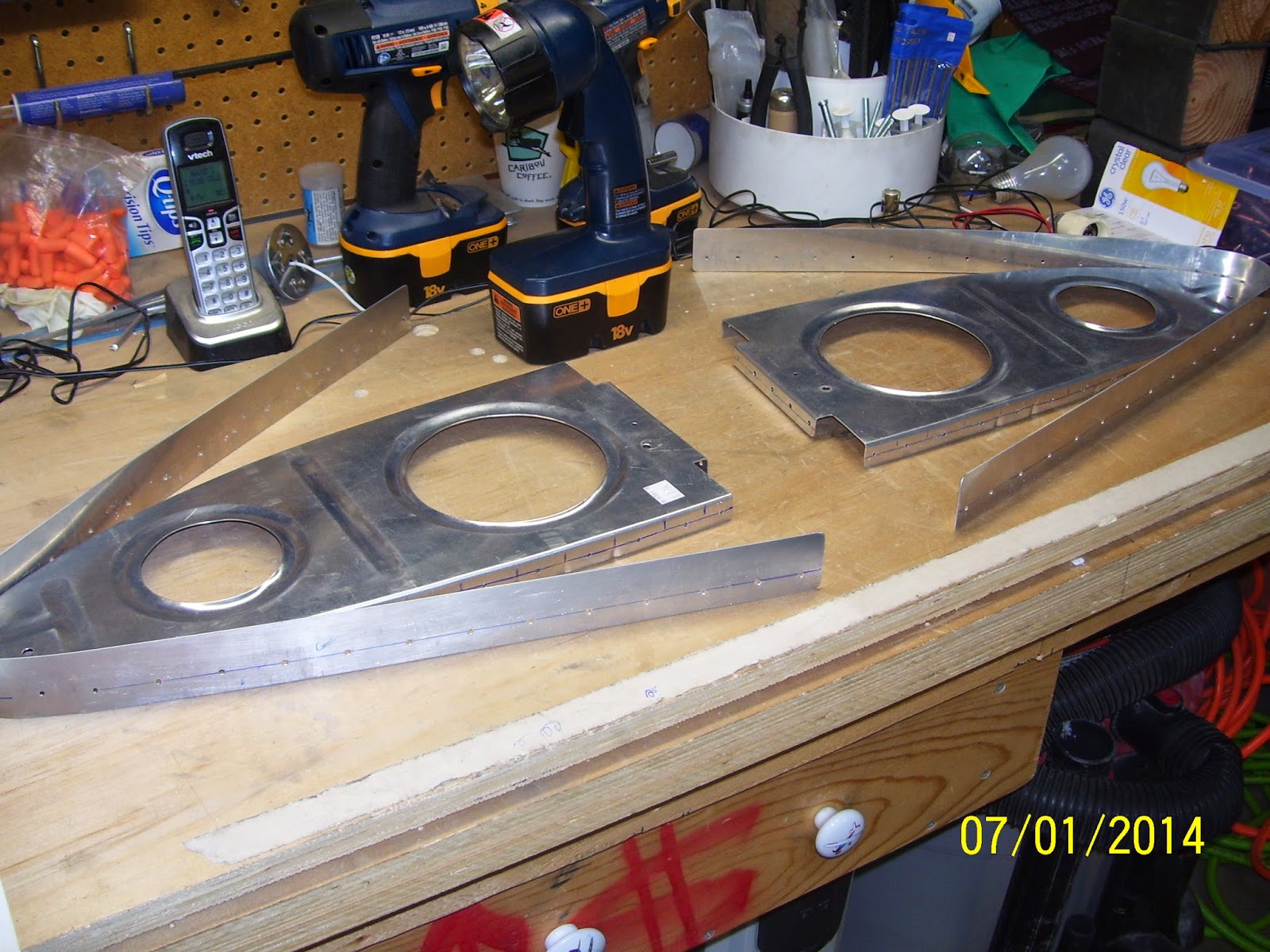
So the short story about the ongoing saga of drilling the joiner plate and W408 ribs for the right wing is that its done for now, but not without a few more anxious moments. As a result of all the "fun" I have now wallowed out the holes in the LE skin pretty good - enough to be concerned about how the dimples will all line up in the quagmire of stupid build steps,all of which may have been resolved if they had just pre-drilled the rear flange of each 408 rib, had you pre-drill one hole in the joiner plate from which to begin that process, and instructed you to draw a line on the rib flanges.

Then, while attempting to remove my drill stop from a dull #40 drill bit, the allen screw became stripped, and I could not get it out. Tried using a stripped screw drill out tool but it did not work,and the local hardware could not find a standard or metric that allen wrench that would work. I then tried a last resort which was to take a dremel tool with the thinnest cutoff wheel that I had and try to cut a slot in the screw so I could unscrew it with a normal screw driver. This attempt failed miserably and the drill stop was all but ruined. Just for the record, when someone gives me a tool and says to make sure that the set screw is on tight to prevent things from slipping, then I make sure it is on tight. That set screw apparently was never going to come out. So my latest rant now goes to Cleaveland Tools for a bad set screw design.

I ordered 2 new ones this time, but not before I attempted to do some of the drilling on the 408 rib without the use of a drill stop. You guessed it. On a couple of holes the drill bit went right through until the tip of the drill chuck banged into the skin, causing some really nice impressions around the hole that I am not certain I will be able to dress out or not. This "HOLE" process has been nothing but a bitch for me. Here is the latest tools order received today from Cleaveland Tools:
Too bad I did not have the drill stops when I drilled out all the rib holes. Shown above are a few more scotch brite pads since rib and LE skin prep for primer is hopefully not too far off into the future. I bought a new unibit (step drill) that starts at 1/8 of an inch and has 1/32 inch graduations. I needed this to help drill out the hole in the LE skin to allow the wing tie down ring to be screwed into the bracket behind the skin. Then I bought a cutoff wheel in preparation for fuel tank ribs and other things, and a very nicely polished 3 pound bucking bar that I plan to use to back rivet the wing skins to the frame and ribs later on.

Here are some pics of the right wing 408 rib drilling exercise, following the same procedure I outlined for the left wing:

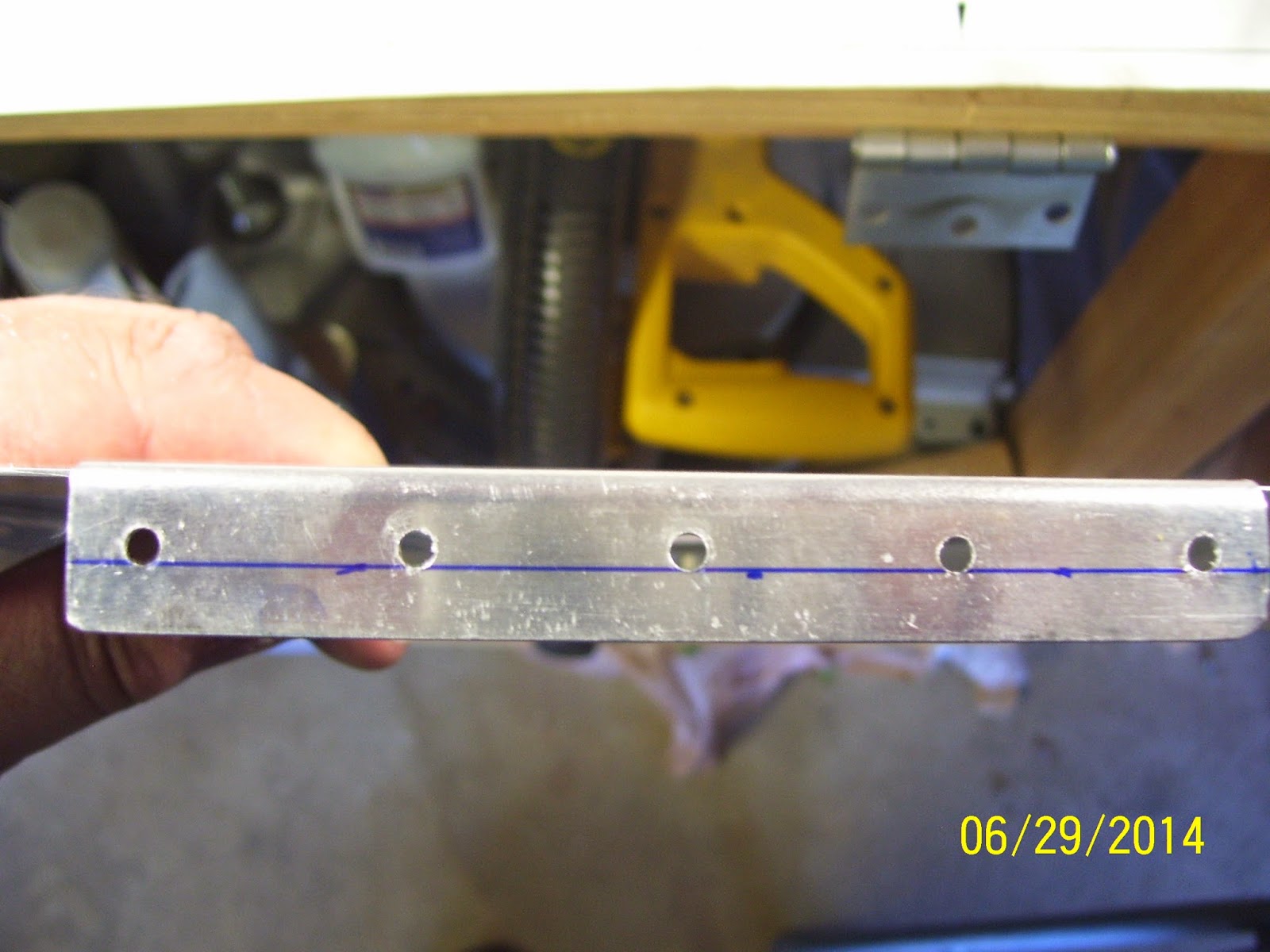
The above holes ended up in about the same place as the left wing rib - about 1/16th of an inch above the min edge distance line shown in the pic. SO at least we have consistency here.

All the rib flange holes ended up where I needed them (Thanks  to the great airplane God!)
I deburred most of the holes and then collasped in disbelief that I had actually completed this step. Unfortunately there is more of this to come for the mod, but I am hoping it will go much easier. Parts are on the way from Vans.


Anyway, with the holes drilled I decided to move on to the next task, and the last one that Vans states in the instructions before starting on the fuel tanks. This is the step where I have to "mark some lines on the main wing skin that will intersect with the center of the Wing Tie Down bracket hole." You know, the ones that I referenced in a previous post when I indicated that the tie down hole cannot be "referenced" by a couple of lines from the skin because directly below this hole is an inspection plate.

So I decided to do some research, and as it turns out, I think I hit a gold mine. There is a fellow in Illinois building an RV-8 that is as detail-oriented as I am. I searched online for for info about the wing tie down bracket hole and how to accurately drill it out. I found a series of pics from this builder that clarified for me how this was supposed to be done. It turns out that it is similar to a method you would use if you were flying VFR, using nothing but a paper map, and were lost. If you had a VOR on board, you would basically triangulate your position by tuning in two separate VOR stations, center the bearing needle on each one, and draw a line on your map from each VOR until the two intersect.The point of intersection is your location.

You perform a similar method to find the center point of the tie down bracket. Vans provides a starting hole for this, but also warns that variations due to builder fabrication of the bolt holes in the tie down bracket may cause deviations of the center point from this pre-drilled #40 hole. As soon as I saw the pic from this builders site I knew exactly how this needed to be done. I guess I am slower than most, because I certainly could not figure out what Vans meant in their instructions. In fact, I just read another set of instructions provided by someone in an article in the latest kit planes magazine about using piano hinges to attach your wing tips to the wings instead of using rivets or screws, and I did not like his textual description of the process either. Too many gaps and not enough detail in his instructions. More typical engineer-type behavior. They can "do it" and show you, but they sure can't write it down very well. Anyway, he provided a lot of pics so you can sort of figure it out if you think about it hard enough.

Anyway, here is the process I used for locating the center of the left wing tie down hole:

1. Cleaned up the shop since there was alot of metal debris from all that drilling
2. Since I obviously did not mark the hole location correctly, I had to remove the left wing LE from the wing, and then replace the outboard bottom wing skin temporarily. I only clecoed it enough to ensure that it was secure against the main wing spar flange, and then clecoed it in a couple of other places on each rib on either side of the tie down hole.
3. I also made a mark on the top of the tie down bracket to show the center from this position,but this is not used as the center point that you will mark on the LE skin.
4. And now for the magic step.  I used my 2 foot long ruler and a couple of clecoes placed as shown on the pic. I had my son hold one edge against the cleco on the skin, and I held the other on the perceived center line of the tie down hole in the bracket. When everything was aligned, I drew a line along the ruler on the lower skin.
5. Then you switch over to the other cleco and do the same thing. Afterward, you end up with a cross pattern in the lower wing skin
6. Then you re-attach the LE to the wing. I only clecoed the rear flanges of the ribs to the wing spar, and only enough clecoes for each side of the inboard section of the leading edge to ensure that it was secured enough to represent where holes should be when everything is riveted on. I did not bother clecoeing the outboard edges of the skin for this. Then you re-align the ruler so that it matches the lines you drew before, and extend those same lines onto the LE skin. IF everything works out, the lines will intersect perfectly through the middle of the #40 hole that Vans drilled. Mine ended up being a little above the center of this hole, so I had to correct for this.

7. SO how did I correct for this. I used a small round file per Vans instructions to file the hole upward just enough to allow the 1/8th inch pilot bit of my new unibit to center up in the correct location:
8. After I filed the hole so that the center point was adjusted upward, I installed my #30 drill bit in the cordless drill (NOT my pneumatic drill).


9. Then I installed the step drill into my cordless drill - no pneumatic drills for this step. Refer to some of my previous posts about how easily this can get away from you, especially if you ar drilling into an open hole with no backing such as a drill board. I was also very concerned about being off center regardless of all this line drawing and measuring, and was very afraid that I would end up destroying the threads in my tie down bracket as a result. So the order of the day for this is to go VERY VERY slow and check the progress frequently - especially after each new step starts to bore into the metal.

I inserted the bit into the pilot hole and began slowly step drilling the hole, checking as I went. I noticed that the hole was definitely still favoring the lower part of the threaded hole for the tie down ring, so I started exerting a bit more pressure upward on the drill. What this means is that I did not file enough off the original hole and should have filed a bit more. Anyway, it looked like I could still adjust for this by applying pressure toward the top of the hole while I continued step drilling. I marked the drill bit with tape so I knew where to stop drilling. I also called Vans about this to find out how large to drill this hole, since they did not bother indicating this either in the instructions or the plans. It needs to be at least 3/8 of an inch for the ring, but I did not know how more clearance might needed or desired. Their input was to drill it out no more that 7/16th of an inch, but certainly drill it a bit more than 3/8 of an inch. My step drill bit had a step for 13/32nds of an inch,so this is the one I used.
10. So this method worked surprisingly well, but it was not entirely fool proof. There are plenty of opportunities to mess this up, so taking it slow of the best advice I have to offer. Use a non-pneumatic drill and go slowly. check and adjust as necessary. Keep the step drill straight as it penetrates the skin. The step drill cleared all the threads in the bracket, so I was happy about that. And the final check, of course, was to verify that the tie down ring can be inserted into the bracket through the new hole in the skin:
11. Wash, rinse, and repeat for the right wing.


Monday, June 30, 2014

Right Wing 408 rib prep (Part 2) continues

Tonight I fluted and straightened the right wing 408 rib (second one). I also inspected the joiner plate that I already drilled with the first rib,and it seems to be in pretty decent shape as far as hole location is concerned, so at least I do not need to fabricate a new W-423 joiner strip. This means that I can follow the same process I did yesterday to set the new rib into position and correctly drill the rib flanges. I will place another order from Vans tomorrow for two more 408 ribs,one more .032 aluminum sheet, and about 6 feet worth of .025 aluminum sheet. Why do I need all that, you may ask? You'll see.

Sunday, June 29, 2014

And progress comes to a screaching halt yet again!!!!! RE-doing the 408 ribs


First I have to rant - this post falls under my Vans sucks category so be prepared. After drilling all the holes in the joiner plate and 408 rib and the LE skin, I decided to remove the assemblies to see how well my holes turned out. I should have done more homework, because I think I hit upon one of the next great blunders in Van's building instructions that are just plain wrong, insufficient, etc. The joiner plates came out mostly OK. The ribs on the other hand are now scrap. The holes on the bottom flange all turned out OK, but the ones on the top, as I came to better understand after researching this a bit more, tend to wander inward as you drill, and therefore the rib flange holes turn out to be much too close to the rib web. There is a problem with the hole being too close to the rib web. Vans has stated that this can weaken the radius where the flange was bent and thus having holes too close to the web is not desired either.The other obvious problem is that you may never be able to get a good dimple for the holes. Here is pic that unfortunately demonstrates the demise of both the left wing and right wing 408 ribs:
So Vans sucks because once again they have failed to provide adequate instructions to help the builder ensure that the outcome of all the time spent on this part of the build can be completed with reasonable success. They tell you to position a completely hole-less rib,and a hole-less joiner plate strip sandwiched between the LE skin and wing spar.Neither the rear flange of the rib nor the skin flanges have any predrilled holes. Not only that, but this assembly is placed together in such away that it is almost completely impossible to clamp it all down correctly with everything exactly in the correct position.

Or so I thought anyway, until I stumbled upon several posts by fellow builders on VAF, the main one being this one:
Correct way to attach and drill 408 ribs and 423 joiner

I ended up using a combination of things from this post to address the problem and ensure a much more favorable outcome - no thanks to Vans - who should have done a much better job of explaining how to do this. This is yet another one of those coveted Vans blunders that forces you to have to order a new part-in this case new W408 ribs.

Step 1
So I have to order new 408 ribs, and if your joiner plate did not come out right then you need to order or fabricate new ones as well. I had already ordered two new 408 ribs so I just happened to have them on hand. I still need to order two more at 23 bucks a pop for my LE mod.

Step 2
Make certain that you mark the flute locations and flute the rib so that it is perfectly straight (or as straight as you can make it, since I have come to realize that NOTHING about metal airplane parts is perfectly straight - especially ribs)

Step 3
I decided to mark the minimum edge distance of the rear rib flange instead of trying to find the center line. Min edge distance for 1/8 inch rivets is 1/4 inch for the AN470AD4 rivets that are used to attach the ribs to the wing spar. Here is the line  and the method I used to draw it. This edge distance was taken from the outer edge of the flange, and not from the rib web. I did it this way because I wanted to know where the maximum outer location of each rib could be. The center of each rivet cannot be any closer than a quarter inch from the outer edge of the flange.
STEP 4
Next, use the following tools to securely fasten the rear of the rib to the wing spar
 - A Large square
- 3 bar clamps - one larger one to clamp the square to the wing spar, and the other two smaller ones to secure the rear flange of the rib to the wing spar. Clamp everything in place, being sure that the rear rib flange is flat against the wing spar web. The edge of the square is placed right up against both sides of the wing skin and along the edge of the wing spar flange, so make sure the edges of the wing skin are clecoed in all holes in this area.
You are clamping the rib to the square in the above pic - be gentle but firm,and check the rear flange through the inspection plate cover (left wing only) to make sure it remains flat against the wing spar web. While I apparently did not take any pics of this, go ahead and slip the old joiner plate in between the rib and the skin before you clamp the rib to the square.This will ensure that the rib is positioned correctly along the perpendicular axis of the wing spar. You won't be able to slip it in at the base because the square will be in the way, nor will it fit all the way in at the top because of this. All you are trying to do is account for the thicknesses of all the materials before you drill the rear rib flange holes. 

STEP 5
Start drilling the holes for the rear rib flange from underneath the wing spar web. Drill one hole and cleco, and check the rib flange to see if the location of the holes looks OK. The goal here is to drill all these holes in a straight line, which I sadly found not to be the case on my original right wing rib.
STEP 6
When done drilling all 5 holes, remove the rib and joiner,etc and inspect the location of the holes in the rear flange. They should be straight, and as the next pic shows they will also NOT align with the min edge distance line that was drawn earlier. I should note that I checked for this line through the holes before I started drilling with a mirror, and I could not see the marks then, which simply told me that the holes will be located somewhere other than at min edge distance. Here is where they actually ended up:
So they are just inside the min edge distance line that I drew, The holes appeared to be in a straight line, so the square technique worked, and they seem to be located on the flange well enough for the rivets to be set, so I am satisfied with this result.

Step 7
Now a reference line needs to be drawn on both the top and bottom rib flanges. The plan for all this is to re-use the drilled joiner plate since those holes are in position already, and use the line drawn on the rib flanges to align the rib through the existing holes in both the skin and the joiner plate. If you are drilling the joiner plate for the first time, then you should assemble all the parts thee best you can, trying to maintain that idiotic 11/16 inch extension of the plate from both the skin and the rib web. Then pre-drill the plate through the wing skin without drilling all the way through the rib. Then remove the joiner plate that you just spent all that time aligning, and finish drilling out the holes on a drill board. Actually, the nice thing about this is that you don't have to try to maintain the 11/16 inch extension. Instead, you should simply focus your attention on the ensuring that the holes in the joiner plate align with the line that was drawn per the plans. Center the line through the wing skin hole and then predrill each hole in the plate. At this point I don' t think it matters much if you do a few holes on one side and then a few on the other. If the half inch line was drawn correctly all you need to do is focus on the line through the wing skin hole.

Once you have final drilled the holes in the joiner plate, remove the rib as described above, and draw a reference line on the rib flanges that will show through both the skin holes and the joiner plate holes. To draw the reference line, you simply use a technique that I learned on Hints for home builders about fabricating a wing rib from scratch. You use your fingers and a set position of the sharpee pen in the desired location of the rib flange (usually the centerline of the flange as best you can eyeball it.) I used the same technique when I drew the line for the forward spar of the horizontal stabilizer. As you can see from the pic it worked pretty well, but the flutes got in the way and distorted it in a few areas.  I must have redone this line about 8 times before I was satisfied with it. I used acetone to remove the line and start over. Always run the line from the bent side of the flange,and never the open end, since that side may have slightly varying dimensions due to the hydro-forming process- especially when dealing with formed ribs.


STEP 8
With the rib flange lines drawn, insert the rib under the joiner plate and skin. Cleco the rear flange in place. Align the wing skin and joiner plate holes, and then slide the rib flange back and forth until the line appears in each hole. I found this to be rather easy to line up both holes and then position the rib flange using the mark. Again, you needn't concern your self so much with the 11/16th of an inch measurement, because as long as your lines are correctly in place through the holes everything should work out in the end. Here is what it should look like when everything lines up:


STEP 9
It is now time to start drilling. The best method is probably to follow the link to the VAF post I provided at the beginning of this post. Start at the flange holes at the rear of the rib, drilling a few of the holes with one hand while ensuring that the flange line marks are centered in the holes with the other hand. IF that first one goes in correctly the rest will be relatively easy to position through each remaining hole. After drilling a few holes at the rear, switch to the 3 holes toward the front or tip of the rib on the same side. Locate the line in the rib flange through those holes and drill them. Remember to put a cleco through every single hole that you drill.

Now switch to the other side of the rib. Note that out of all the holes that got messed up on mine, all the bottom flange holes were fine. It was only the topside holes that got messed up. So pay very close attention to the top flange holes and ensure that the line can be seen centered through each hole as best as possible. Follow the same routine to drill the same holes on the other side. Then switch back and forth between sides, drilling out a few more holes until you are done.

STEP 10
When all holes are drilled and clecoed, remove them, including the ones holding the rear rib flange to the wing spar. Remove the entire rib/joiner plate assembly, and inspect all hole locations in the rib flanges and the joiner plate and the wing skins to ensure they were not abnormally enlarged during the drilling. This time the holes came out much better aligned and in the location I expected them to be to ensure that edge distance and space for dimples was maintained:
NOw,why is this 11/16th of an inch thing so important? Well,simply put, there needs to be sufficient flange material to allow the drilling, dimpling and attachment of nut plates that will use a number 8 screw to attach the LE to the fuel tank. I checked the plans, which show a full sized drawing of the gap between the LE and fuel tank,and shows where the joiner plate and fuel tank ribs are located. There is supposed to be about a 1/16th of an inch gap between the joiner plate edge and the last fuel tank rib web, so exceeding the 11/16 length may cause interference with the fuel tank rib. On the other hand, too little material may cause problems setting the dimples for the nut plates correctly. Again, if all the reference lines in the joiner plate and rib were drawn and drilled correctly, I think this pretty much works out for itself. Your last step in this process is to check the joiner plate length against both the LE rib web and the LE skin edges. If you have roughly 11/16th of an inch on both sides then this is a win and you can move on.


With the left wing joiner plate/408 rib done to my satisfaction, I will now need to repeat the same process for the right wing. Funny, I was expecting to be working on mod today, but instead I had to re-do everything I did yesterday. The scary part is that I essentially have to do this same thing all over again for the mod, except this time it is in a rib location where I have even less access for positioning and viewing the rib than I did for this one. And so it goes. Vans, today you sucked!

Saturday, June 28, 2014

Right Wing LE Rib flanges drilled, started LE modifications

Made good progress on the right wing LE. Got the ribs installed to the skin and the assembly mounted to the right wing spar. Drilled all the rib-to-spar flanges, and then proceeded with the prep of the W408-1-R inboard rib and W-423 joiner plate.

I marked the locations in between the holes where I could flute the rib to straighten it, and applied the flutes. I then straightened and deburred the rib flanges using the flange bending tool and a mallet and straight edge. For the joiner plate, this time, instead of pre-forming it somewhat free-hand, like I did for the one for the left wing, I decided to be a bit more deliberate by taking the rib and setting it firmly on the work bench. Then I used my cleco clamps to incrementally secure the joiner strip all the way around the rib flanges as shown:
The short clamps worked on the very edges, but would not reach the flanges around the sides. the longer clamps worked for the sides, but just barely. I kept the rib flat on the bench and worked the strip around the front, keeping its edge flat on the bench as well. One problem I had before I shot this pic was that I placed wrong strip edge on the bench so the sharpee mark I made was in the wrong place. SO the curve was in the wrong place and I had to rework this a bit after I flipped the strip over so that the mark was located over the rib flange as shown above. So make sure you don't bend it with the mark in the wrong place. Anyway, I seemed to be able to reform it well enough. Even after doing this I found that you still need to apply some force to the round front of the strip to help keep it bent in such a way that will naturally following the curve of the rib. It does not take much, and if you squeeze it in the wrong location you will have to keep reworking it. Here is the pre-bent strip after I finished working on it and clamps were removed:
Then I set out to position the rib and the joiner plate against the right wing LE skin. Then tried to line everything up just as before. Also just as before, this turned out to be a chore trying to position a loose rib and joiner strip all at the same time to achieve the specified measurements to ensure that the rivet holes are drilled in the correct spot for everything. After about 20 minutes of screwing around with it, everything seemed to magically finally fall into place. So I clamped the skins to the rib and joiner plate just as before, re-measured the distance between the rib web and the end of the joiner plate one last time, which requires 11/16 inches all around, and started drilling.

Got all the LE rivet holes drilled, patted myself on the back, and then set out to begin the process of the LE modification that I have been planning for a long time now. For those builders that are following me, if you plan to continue with the stock build of the RV, then you will need to advance to the step in the instructions that says to leave the Le in place and start working on the fuel tanks. For me, this will need to wait until my modification has been completed successfully.

Some things about the mod I will post openly here. Other things will be recorded separately, and I will wait before sharing them after I determine that the steps I employed seem to work correctly. Always remember that anyone following this blog that desires to employ any of the methods I describe, does so at their own risk. Everything I am doing is based on my own research and experimentation, and although there is very little risk of anything going wrong during the build, there is risk that my plans may not work the way I intend them to, and this will only be determined by extensive flight testing long after this mod has been completed.

I am starting the mod with the left wing LE. The process begins by receiving yet another 408-1-L inboard LE rib from Vans, in addition to a piece of .032 x 12 inch x 36.5 inch aluminum sheet. Basically I am going to be replacing the first W-709 LE rib just outboard of the first W408-1-L rib with another W408-1-L rib, cutting out the section of the LE skin in the first inboard bay of the LE, and refabricating a "new" much larger W-423 joiner plate by extending the W-423 all the way across and between both 408 ribs.

It started with fluting and straightening of the new 408 rib.Same process as all the others.This is how I marked the locations where the flutes can be applied, by inserting under the existing joiner plate just far enough to keep it in position so could place pen marks in between all the rivet hole locations:
Here is the aluminum sheet that ordered from Vans. They messed up my order so I need to get another one of these for the right wing,but I also need to order some more .025 sheet as well. I will trim this down to some measurement between 36.5 inches and some other measurement that is a bit longer that I have not yet determined. I order it to be 3 feet and 6 inches long so I had enough extra to work with. The width is 12 inches, and before it is all said and done I may be trimming that dimension down just a bit as well, but I am undecided on that just yet.
Here are some shots of the file that I used to knock down the "bumps" on the front of the LE rib sections:
Here is a shot to elaborate on what I mentioned earlier about replacing one of the W709 LE ribs with another W408 rib. Basically I will have two 408 ribs in the first two inboard sections of the LE.
And then finally something I just could not resist. Can't wait until this mod is done!
This assembly gets glassed onto a removable LE section, but all the necessary substructure mods need to be made first, to ensure that strength will be maintained.
I feel almost giddy now that this is starting to take shape. Looks pretty cool, but will look even cooler as I get this done.


Tuesday, June 24, 2014

Started prep for the right wing LE

Last night I finished drilling the remaining holes in the left wing leading edge. There were a couple of additional pics I wanted to show regarding the drilling process for the rib flanges to the wing spar. This first one shows a neat trick that I discovered to put more light on the underside of the wing spar. Using my Ryobi flash light (I love this light), I found that you can rotate the head all the way up, and then set it toward the far end of the bay immediately behind the bay that you are working in, and the light shines right on the spot of the wing spar web that you are working on. Worked really well for me.

And next is a pic that shows the bolt and nuts being removed to allow me to get the drill into the two holes either side of center. This did turn out to be a non-issue, and it took about 15 minutes to get both holes match-drilled and replace bolt and nut assemblies. Also notice the light from the flash light.....

And here is a shot of the drill bit and the rough position of the drill in order to drill out these holes in the wing spar web. It gives you an idea of the amount of bend that can be applied to the drill bit to keep the drill outof the way of the airplane parts and still drill a straight hole in the spar web.
Another strange thing happened to me while I was drilling out these holes. I found that I could not focus very well with my glasses on. If I removed them the spar holes were much clearer - so I drilled them all with my glasses off. Could it be that my vision is improving?
I also had a great show this past weekend right over my own house from the EAA B-17 Aluminum overcast, which was in town for its annual pilgrimage and promotional flying tour leading up to Airventure. Luckily it escaped another hail episode,but the weather was threatening on a couple of the days that it was here. Because of that, last Saturday afternoon I was treated to a direct overflight of the B-17not once, not twice, but three times before it departed and headed back to KAPA. What a treat that was. I really love where I live because it is a key reference point for most exhibition flights, including the F-16 overflights of Mile High Stadium during the Bronco games and a whole host of other local T-6 and P-51 activity from time to time. I even see some RVs every once in a while.

With the left wing LE holes drilled, it was time to start working on the LE for the right wing. I removed the vinyl from the inside of the LE, and then I prepped the nose sections of all of the LE ribs. Here is a shot of the LE:
and here is a pic that shows the end result of the smoothing out of the bumps that occur from the nose sections of each rib that are bent over to form the nose of the rib. In their rough form from the factory there are very noticeable ridges between each separate flange as they move around nose section of the rib. I had to back up a page or two in the instructions,but Vans does specifically mention to remove these"bumps to avoid transferring these distortions to the LE skin. They just don't tell you exactly how to do it. This is where I used my standard flat file and ran over the flange joints as many times as necessary, until each section felt nice and smooth to the touch. I ran my finger across each separate section until I was satisfied that it was as smooth as I though it should be, being careful not to remove too much material. Having said that, I did remove a fair amount of metal from some of the flange joints. Each rib was just a bit different so you have to customize the smoothing of each one. This next pic is a bad one but attempts to show the amount of material I removed to achieve smoothness of the nose section of each rib:
If you catch your finger on one of the flanges you need to keep removing material a couple of scrapes at at time until you can run your finger around the entire nose section without catching a ridge. This ensures that your LE skins will also remain smooth.

Tomorrow I started clecoing LE ribs to the skin and setting it on the right wing spar and match drilling those holes.I should also mention that I received a package from Vans with a parts order that I need to start working on my LE mod. I think I have that all worked out, but it is still somewhat involved in order to make it all come together correctly. More on that later...

Lastly  special shout out to my friends Mike and Anetta Rettig, who gave birth to a healthy new baby boy the other day. Best wishes to all of you and Amelia too. I am anxiously waiting on specifics but mom and baby are recovering and when I know more I will post more.

Work continues........looking more and more like wings everyday. Fuel tanks are getting closer to the top of the work list.....