One Wing Stand down, one more to go, and then a few other minor details, etc., etc.
Working last night and again tonight, I was able to finish fabricating the threaded rod brackets and drilling the remaining holes in the other side of Wing Stand # 1. So the supports are essentially done for one wing stand. this first pic of the threaded rod brackets after I drilled one 1/4 inch hole and one 5/16 inch hole for each bracket.
Next is a series of pics showing the completed assembly of one support:
I just noticed that the store label on the outside of the support angle gives an optical illusion of the angle being slightly bent in the above photo - wierd! I will remove this later to keep it from paying tricks on my mind as I build the wings.
With that side done, it was time to finish the other side. First was the bottom side hole - same as the first side - 9.25 inches below the mounting hole for the support angle. I measured and marked the spot just as before, and drilled the hole on the first side of the stand. This next pic shows what I think I tried to describe in earlier posts but may not have done so very clearly. Pics are worth a thousand words. THis shows how I measured the precise location of the first hole so I could transfer the dimensions over to the other side with reasonable certainty that they were the same. The straight edge is clamped so that it serves as a hard stop for the tape measure.
I transferred the dimensions over to the other side of the stand. This time the hole lined up almost perfectly. I then drilled the other 1/4 inch mounting hole in the angle bracket, and it was time to assemble the hardware for that side.
And then the final touch. To prevent the rough steel angles from scuffing the wing spars during assembly on the stand, I placed Gorilla tape over the tops of both angle supports. The spar will be clamped in place on one end, and the outboard end of the wing will be attached to the opposite support angle via yet another support angle that will be drilled and mounted to the last wing rib, and susequently to the top of the attached support angle bracket. Again, easier to see than to describe.
Anyway, feels good to complete the brackets for one wing stand. Now I just have to measure and drill and mount the supports for the other stand. Since tomorrow is Valentines day, adn the following day is my local EAA chapter 301 meeting night, I may not get this done until this weekend, but it will get done. You keep celebrating the small victories, and one day they all add up to one huge victory celebration when that first flight is entered into the logbook and engrained into your memory forever. Still looking forward to that day, whenever it may be.
Wednesday, February 13, 2013
Monday, February 11, 2013
Threaded Rod brackets, Cont'd.
Tonight I managed to brave the cold long enough to cut the remaining 7 bracket angles from the 1.5 x1.5 x 1/8 inch thick aluminum angle I used as a backer plate when I drilled the nut plates for the wing spars. I needed 7 more for a total 8. This is 2 per side, 2 sides per stand, and 2 sets of stands. I was able to find enough width in between nut plate holes to satisfy the requirements for each angle bracket. Most of them are between 1 1/8 to 1 1/4 inch wide, and this is fine.
Here are the raw blanks after I measured and cut them on my band saw. I really love my full sized band saw. The standard wood blade that it came with does a fine job cutting medium to heavy gage aluminum like butter. Do not use it to cut thin aluminum sheet, though.
Since the angle was a bit too long on both edges for my needs, I trimmed both ends another 1/4 inch, and ran them over mt scotch brite wheel to debur the cut edges, which are measured and marked in this next photo:
Then I measured both sides for the center point, and took the washers I am using for the 1/4 inch mounting bolt and the 5/16 inch threaded rod, and drew the pattern for each washer on the angles. Each bracket will have one 1/4 inch hole on one side and one 5/16 inch hole on the other side.
The finished "prototype" is in the foreground in the above pic. All I need to do now is drill the holes and finish trimming each one. Then all I need to do to finish up is drill the holes in the remaining angle supports and wing stands and I will finally be ready to support the wings on each stand. Man what a process this is. It's alot of work, but well worth it in my opinion. I can't wait to put it to the test.
Here are the raw blanks after I measured and cut them on my band saw. I really love my full sized band saw. The standard wood blade that it came with does a fine job cutting medium to heavy gage aluminum like butter. Do not use it to cut thin aluminum sheet, though.
Since the angle was a bit too long on both edges for my needs, I trimmed both ends another 1/4 inch, and ran them over mt scotch brite wheel to debur the cut edges, which are measured and marked in this next photo:
Then I measured both sides for the center point, and took the washers I am using for the 1/4 inch mounting bolt and the 5/16 inch threaded rod, and drew the pattern for each washer on the angles. Each bracket will have one 1/4 inch hole on one side and one 5/16 inch hole on the other side.
The finished "prototype" is in the foreground in the above pic. All I need to do now is drill the holes and finish trimming each one. Then all I need to do to finish up is drill the holes in the remaining angle supports and wing stands and I will finally be ready to support the wings on each stand. Man what a process this is. It's alot of work, but well worth it in my opinion. I can't wait to put it to the test.
Fabricating and Positioning Threaded Rod Brackets
This weekend I managed to locate and drill the hole on the opposite side of the wing stand post that secures the angle bracket to the wing stand. I also started the process of fabricating the brackets that will receive both ends of the adjustable threaded rod that will brace the support angle that holds the wing spar. I need to make 8 brackets, and there is a bit of measuring and fabrication work involved, as usual.
The process I used to lcoate the matching hole on the opposite side of the wing stand was to clamp a straight edge across the wing stand so that could get a precise measurement from a another ruler as to the exact distance of the edges of the drilled hole from the edge of the wing stand, as shown below:
I placed the edge of the second ruler up against the straight edge to get an exact measurement. Then I measured from the top of the wing stand to the top and bottom edges of the hole. Now I have all 4 measurements needed to draw the matching lines on the opposite side of the stand as shown above. I marked and drew the reference lines as shown after reclamping the straight edge across the short side of the stand as shown above. Then I center punched the stand and drilled the hole. The test to determine if I did this right was simple - if I could continue to push the drill striaght through to the hole on the opposite side, I did it right. Luckily it worked pretty well, and the holes were aligned as expected.
Next came the brackets for the threaded rod supports. I used 5/16 inch threaded rod, and 1/4 inch hardware for these. I also used remnant from the 1.5 x 1/8 inch aluminum angle that I used to drill the nut plate holes in the wing spar flanges. I cut the angles down to 1.25 inches. After making some calculations to allow for bolt head and washer thickness, I determined that probably not more than a 1 inch piece of angle is needed, but I wanted something a bit wider to help counteract any tendancy for the angle to distort or become compressed when the weight of the wings is applied.
First step was to determine where to locate the hole in the stand. I used the pythagorean theorem to determine this. That formula is a squared plus b squared equals c squared for a right triangle. the "C" value is already determined, and this is the length of the threaded rod, which makes up the hypotenuse of the triangle that is formed by this arrangement. it is 12 inches long. The other measurement that is known is the B measurement. This is 6 inches from the location of the wing stand attachment hole in the support angle to the hole in the support for the threaded rod bracket. That leaves only the A measurement to solve for. I wanted to find the measurement that would allow me to use the stock 12 inch length of the threaded rod without the need to cut or debur the ends of that. It turned out at 9.25 inches left a C measurement of just over 11 inches. This would leave approximately 1/2 inch on either end of the threaded rod to allow for adjustments to keep the wing true with no twist or distortion. SO the measurements of the triangle formed by this support are 6 x 9.25 x 11 inches.the reality is that there is much more thread to use for adjustments because the attach points for the rod are well forward of the center mounting hole of the bracket. This will become more clear with more pics.
So I did my best to mark and drill 2 more holes in the same wing stand that were 9.25 inches below the first hole. this did not turn as well as the first set of holes as far as alignment of the holes on either side of the stand was concerned. I think the drill slipped a bit, and so the bottom bolt is at a slight angle compared to the top bolt. Regardless, I think it will work fine.
Here is the pic of the first hole, again after carefully measuring the location in reference to the forst bolt hole above:
And the second hole on the other side:
And then came the bracket:
It has to be tapered to accept the threaded rod that connects the angle support to the wing stand. I will have more pics as this all comes together. Still a lot of work to do, and 7 more brackets to fabricate. It may take me the majority of next week to finish everything for both Wing stands, but it will get done.
The process I used to lcoate the matching hole on the opposite side of the wing stand was to clamp a straight edge across the wing stand so that could get a precise measurement from a another ruler as to the exact distance of the edges of the drilled hole from the edge of the wing stand, as shown below:
I placed the edge of the second ruler up against the straight edge to get an exact measurement. Then I measured from the top of the wing stand to the top and bottom edges of the hole. Now I have all 4 measurements needed to draw the matching lines on the opposite side of the stand as shown above. I marked and drew the reference lines as shown after reclamping the straight edge across the short side of the stand as shown above. Then I center punched the stand and drilled the hole. The test to determine if I did this right was simple - if I could continue to push the drill striaght through to the hole on the opposite side, I did it right. Luckily it worked pretty well, and the holes were aligned as expected.
Next came the brackets for the threaded rod supports. I used 5/16 inch threaded rod, and 1/4 inch hardware for these. I also used remnant from the 1.5 x 1/8 inch aluminum angle that I used to drill the nut plate holes in the wing spar flanges. I cut the angles down to 1.25 inches. After making some calculations to allow for bolt head and washer thickness, I determined that probably not more than a 1 inch piece of angle is needed, but I wanted something a bit wider to help counteract any tendancy for the angle to distort or become compressed when the weight of the wings is applied.
First step was to determine where to locate the hole in the stand. I used the pythagorean theorem to determine this. That formula is a squared plus b squared equals c squared for a right triangle. the "C" value is already determined, and this is the length of the threaded rod, which makes up the hypotenuse of the triangle that is formed by this arrangement. it is 12 inches long. The other measurement that is known is the B measurement. This is 6 inches from the location of the wing stand attachment hole in the support angle to the hole in the support for the threaded rod bracket. That leaves only the A measurement to solve for. I wanted to find the measurement that would allow me to use the stock 12 inch length of the threaded rod without the need to cut or debur the ends of that. It turned out at 9.25 inches left a C measurement of just over 11 inches. This would leave approximately 1/2 inch on either end of the threaded rod to allow for adjustments to keep the wing true with no twist or distortion. SO the measurements of the triangle formed by this support are 6 x 9.25 x 11 inches.the reality is that there is much more thread to use for adjustments because the attach points for the rod are well forward of the center mounting hole of the bracket. This will become more clear with more pics.
So I did my best to mark and drill 2 more holes in the same wing stand that were 9.25 inches below the first hole. this did not turn as well as the first set of holes as far as alignment of the holes on either side of the stand was concerned. I think the drill slipped a bit, and so the bottom bolt is at a slight angle compared to the top bolt. Regardless, I think it will work fine.
Here is the pic of the first hole, again after carefully measuring the location in reference to the forst bolt hole above:
And the second hole on the other side:
And then came the bracket:
It has to be tapered to accept the threaded rod that connects the angle support to the wing stand. I will have more pics as this all comes together. Still a lot of work to do, and 7 more brackets to fabricate. It may take me the majority of next week to finish everything for both Wing stands, but it will get done.
Friday, February 8, 2013
Drilling holes for the support brackets
Tonight I managed to carve out a small chunk of time to start the process of mounting the support bracket to the wing stands. These angle brackets will act as the shelves that will support each wing spar. Last night it rained and then froze and then snowed, and so it was bit too cold to work in the garage. Tonight it was not quite so bad outside, so off to work went.
This process is much the same as any other process on this project, if you want to do correctly. It involves a lot of measuring, positioning, clamping, leveling, and drilling. Gee that sounds awfully familiar for some reason!
The steps for setting the support angles went something like this:
1. Drill the first support bracket mounting holes on the 2 inch center that was previously marked on each support angle. I am using 1/4 inch hardware for this, so I drilled a 1/4 inch hole. I used a center punch but the drill bit I used still wandered a bit. It is for this very reason that I wanted to drill the holes in the support angles first, instead of drilling the holes in the wing stands. That way I can use the final hole of the bracket to match drill the hole in the wing stand later.
2. Determine the height of each support bracket- I settled for about 48 inches above the floor of each wing stand and made a couple of marks on each stand accordingly
3. Clamp one of the support angles into position. Use a small level to verify that the support bracket on one end is truly level.
4. Determine what the "true" level height should be for the bracket on the other wing stand as follows:
Remember that my garage floor is anything but level, and so simply measuring 48 inches for each stand and clamping both support brackets in place is probably not going to really give me a level-sitting wing spar. Why all this fuss about leveling the wing spars? Simple. Even though the ribs and skins are prepunched for an exact match, once you start clecoeing them to the ribs, gravity will still have a tendency to pull on the entire assembly to the point where you may end up with some slight mismtaching of the skins. Better to ensure everything is truly level so that the skins will want to fall straight down perpendicular to the wing spars, and the ribs will do the same.
To resolve this I used some fishing line and several line levels like the ones shown in the pic below.
With the help of my son we stretched the fish line across the wing stands with the line levels in place to check for true level between the stands. One end was placed directly on top of the clamped support bracket on one side, and the other was stretched across to the other wing stand, and a mark was placed on the short side of the wing stand along the fish line, after verifying that the line levels were truly level.
This is where it gets a bit comical. I knew that I may have to adjust my marks on the stands by perhaps one or two inches, but when we used the yellow line levels to check for level, I mistakenly thought that the bubble needed to be inside the black lines in the middle of the level. This resulted in an offset of about 6 inches from one stand to the other. Really, I need to set one support bracket 6 inches higher than the other one on the othe stand??! Not believing this for a second, I decided to switch to the more normal looking blue line levels, and of course, this time I only need to adjust the marks on the opposite wing stand by about .5 inches. That made a heck of alot more sense. My floor is bad, but not "that" bad!
Then I finally figured out what I did wrong. These yellow levels display several marks that show different offset values from level, so that you can set specific grades for drainage for things like driveways, sidewalks, etc. I should have set the fish line so that the edge of the bubbles on these levels just meets the line marked 0, and the rest of the bubble is on the clear side, opposite the side with the marks. SO whne you want the bubble to show "level" it is not located in the actual center of the level. What a messed up tool! Just goes to show you that no matter how seemingly insignificant a tool is that you might use for your build, you must know how to use them properly, or you may risk really end up screwing something up. I re-measured everything again with the yellow levels just to satisfy my curiosity, and of course the marks ended up being about the same as with the blue line levels. What a relief.
5. I used a square to carry the previous mark around to the inside long edge of the wing stand. This is the line that the support bracket must align with to keep everything level.
6. Then I clamped that bracket into place using two bar clamps on either side of the 1/4 inch hole that I previously drilled. This allows me to use the hole in the bracket as a pilot hole for drilling the first hole in the wing stand. I used some boelube and the cobalt drill bit to match drill the hole for the bolt that will be inserted into the wing stand and support bracket.
And this is where I called it a night. Next step will be to accurately measure the location of the bolt hole on the other side of each wing stand so that it lines up with the holes that I drilled tonight. There are several ways to accomplish this to ensure that the bolt holes are straight across from each other, and I will explore which method I want to use and post more about that tomorrow. I do not trustmyself to keep the drill straight enough to continue drilling the hole on the outside of the stand by using the hole on the inside as a guide. I have very poor luck with free-hand drilling holes like that. They always end up a little off. So I will take my time here and do this right.
Closing with some pics of the work done tonight:
This process is much the same as any other process on this project, if you want to do correctly. It involves a lot of measuring, positioning, clamping, leveling, and drilling. Gee that sounds awfully familiar for some reason!
The steps for setting the support angles went something like this:
1. Drill the first support bracket mounting holes on the 2 inch center that was previously marked on each support angle. I am using 1/4 inch hardware for this, so I drilled a 1/4 inch hole. I used a center punch but the drill bit I used still wandered a bit. It is for this very reason that I wanted to drill the holes in the support angles first, instead of drilling the holes in the wing stands. That way I can use the final hole of the bracket to match drill the hole in the wing stand later.
2. Determine the height of each support bracket- I settled for about 48 inches above the floor of each wing stand and made a couple of marks on each stand accordingly
3. Clamp one of the support angles into position. Use a small level to verify that the support bracket on one end is truly level.
4. Determine what the "true" level height should be for the bracket on the other wing stand as follows:
Remember that my garage floor is anything but level, and so simply measuring 48 inches for each stand and clamping both support brackets in place is probably not going to really give me a level-sitting wing spar. Why all this fuss about leveling the wing spars? Simple. Even though the ribs and skins are prepunched for an exact match, once you start clecoeing them to the ribs, gravity will still have a tendency to pull on the entire assembly to the point where you may end up with some slight mismtaching of the skins. Better to ensure everything is truly level so that the skins will want to fall straight down perpendicular to the wing spars, and the ribs will do the same.
To resolve this I used some fishing line and several line levels like the ones shown in the pic below.
With the help of my son we stretched the fish line across the wing stands with the line levels in place to check for true level between the stands. One end was placed directly on top of the clamped support bracket on one side, and the other was stretched across to the other wing stand, and a mark was placed on the short side of the wing stand along the fish line, after verifying that the line levels were truly level.
This is where it gets a bit comical. I knew that I may have to adjust my marks on the stands by perhaps one or two inches, but when we used the yellow line levels to check for level, I mistakenly thought that the bubble needed to be inside the black lines in the middle of the level. This resulted in an offset of about 6 inches from one stand to the other. Really, I need to set one support bracket 6 inches higher than the other one on the othe stand??! Not believing this for a second, I decided to switch to the more normal looking blue line levels, and of course, this time I only need to adjust the marks on the opposite wing stand by about .5 inches. That made a heck of alot more sense. My floor is bad, but not "that" bad!
Then I finally figured out what I did wrong. These yellow levels display several marks that show different offset values from level, so that you can set specific grades for drainage for things like driveways, sidewalks, etc. I should have set the fish line so that the edge of the bubbles on these levels just meets the line marked 0, and the rest of the bubble is on the clear side, opposite the side with the marks. SO whne you want the bubble to show "level" it is not located in the actual center of the level. What a messed up tool! Just goes to show you that no matter how seemingly insignificant a tool is that you might use for your build, you must know how to use them properly, or you may risk really end up screwing something up. I re-measured everything again with the yellow levels just to satisfy my curiosity, and of course the marks ended up being about the same as with the blue line levels. What a relief.
5. I used a square to carry the previous mark around to the inside long edge of the wing stand. This is the line that the support bracket must align with to keep everything level.
6. Then I clamped that bracket into place using two bar clamps on either side of the 1/4 inch hole that I previously drilled. This allows me to use the hole in the bracket as a pilot hole for drilling the first hole in the wing stand. I used some boelube and the cobalt drill bit to match drill the hole for the bolt that will be inserted into the wing stand and support bracket.
And this is where I called it a night. Next step will be to accurately measure the location of the bolt hole on the other side of each wing stand so that it lines up with the holes that I drilled tonight. There are several ways to accomplish this to ensure that the bolt holes are straight across from each other, and I will explore which method I want to use and post more about that tomorrow. I do not trustmyself to keep the drill straight enough to continue drilling the hole on the outside of the stand by using the hole on the inside as a guide. I have very poor luck with free-hand drilling holes like that. They always end up a little off. So I will take my time here and do this right.
Closing with some pics of the work done tonight:
Tuesday, February 5, 2013
Cutting support angle brackets
Tonight I measured and cut my 1 1/4 inch x 1/8 inch thick steel angle in 4 pieces, each 13 inches long. I used the recprocating saw with the metal cutting blade - the same one I used to bevel the corners of the wing stands. This was like cutting through butter compared to the 1/4 inch thick wing stands, so it went fairly quickly.
The widest part of the wing spars is about 7.75 inches wide, so a one foot long piece of angle would allow the spar to just fit nicely on the entire support. Since 4 inches are aligned with the inside edge of the wing stand, that leaves 9 inches for the spars to rest on, which should be plenty. I opted to cut them a little longer than necessary, mostly to allow for the 1/4 to 1/2 inch adjustment that may be needed to level each angle after attaching them to my wing stands.
I also measured and marked the 4 support angles for the first of two holes that need to be drilled in each support bracket - one for the attachment bolt to the post, and the other to accept the bracket that will hold the 5/16 inch threaded rod. I expect to be drilling most of the remaining holes tomorrow after work.
No pics tonight, but I did manage to visit Aaron Miller's build log to check up on his progress since we got the wing stands welded together. This post shows some pics he took of me "in action" with a welder in my hand. Dangerous stuff for sure! Looks like he is up and running with both his wings. I envy the room he has in his basement. Before long he will be wheeling his entire airplane out of the basement and onto his taxi way where he will taxi all the way to the runway for his first flight.
ON another note - Looks like Van's has officially indicated on their facebook page that they have reached a new milestone of 8000 flying RVs! What an amazing accomplishment, considering that they were already the most popular flying kit airplane manufacturer when they only had 6500 of them flying not so long ago. Guess I better get busy and finish this thing!
And finally, looks like friend and fellow builder Ron Duren made the big move to KBJC last weekend. Congrats to him - he really put in a lot of work to get things to this point, and I think he is well on his way to a probable first flight some time this coming spring.
The widest part of the wing spars is about 7.75 inches wide, so a one foot long piece of angle would allow the spar to just fit nicely on the entire support. Since 4 inches are aligned with the inside edge of the wing stand, that leaves 9 inches for the spars to rest on, which should be plenty. I opted to cut them a little longer than necessary, mostly to allow for the 1/4 to 1/2 inch adjustment that may be needed to level each angle after attaching them to my wing stands.
I also measured and marked the 4 support angles for the first of two holes that need to be drilled in each support bracket - one for the attachment bolt to the post, and the other to accept the bracket that will hold the 5/16 inch threaded rod. I expect to be drilling most of the remaining holes tomorrow after work.
No pics tonight, but I did manage to visit Aaron Miller's build log to check up on his progress since we got the wing stands welded together. This post shows some pics he took of me "in action" with a welder in my hand. Dangerous stuff for sure! Looks like he is up and running with both his wings. I envy the room he has in his basement. Before long he will be wheeling his entire airplane out of the basement and onto his taxi way where he will taxi all the way to the runway for his first flight.
ON another note - Looks like Van's has officially indicated on their facebook page that they have reached a new milestone of 8000 flying RVs! What an amazing accomplishment, considering that they were already the most popular flying kit airplane manufacturer when they only had 6500 of them flying not so long ago. Guess I better get busy and finish this thing!
And finally, looks like friend and fellow builder Ron Duren made the big move to KBJC last weekend. Congrats to him - he really put in a lot of work to get things to this point, and I think he is well on his way to a probable first flight some time this coming spring.
Monday, February 4, 2013
....And for tonight's math lesson........
....We will perform a variety of calculations to arrive at the measurement for the the desired height for the shelving brackets that will support the wing spars. There are a couple of things to consider here:
1. What is the comfortable standing height that I can easily rivet the skins to the spar and ribs?
2. Do I need to leave enough room at the bottom of the stand to position the control surfaces (ailerons and flaps) from the trailing edge, and if so, how much room do I need to leave?
A couple of general measurements were taken of the main ribs, the leading edge ribs, the wing spar flanges, and the overall width of the entire wing assembly.
Overall width of the wing according to the wing tip: Approx 60 inches, or 5 feet
Main rib: 26.5 inches
Leading edge rib: 17.5 inches
Total of main and leading edge ribs: Approx 44 inches, plus about 1/16th inch for the thickness of the spar and another 1/16th for the trailing edge spar.
60-44 leaves 16 inches. This is the amount of space I would need to leave on the bottom if I wanted to be able to attach the finished control surfaces to the TE of the wing while they are still in the stands. I think most folks are attaching these when the wing is removed from the stands and placed inthe wing cradle so that the TE is now facing up, making the hinge attach points a bit easier to manage. So I don't think that leaving enough space for the control surfaces on the bottom is a major consideration.
Another aspect of this to consider is that if I do decide to leave enough room on the bottom, a jack will have to reach up that far to support the middle of the wing that naturally starts to sag in the middle when everything is attached to the wing spar until the wing skins are riveted into place. The higher the gap the longer the jack needs to reach to support the rear spar.
When I stood in front of the wing stands, I found that my arm comfortably supports the rivet gun and drill at about 48-50 inches from the floor. Aaron told me that he positioned his support brackets at about 55 inches, but he is also notably taller than I am, so I would naturally expect that from a standing position my brackets would probably be a bit lower than his.
Here is a pic, courtesy of Sean Thomas' RV-7 project, that shows the relative height of his wing stands:
Although I did not measure the height of his support brackets, they also appear to be more along the 48 inch high range. One other consideration for this is a comfortable sitting height when the time comes to rivet the skins on one side of the wing. You want to be able to sit in a chair and comfortably reach from the highest to lowest rivets along each rib while you rivet the skins together.
A few more calculations:
16 + 26.5 (gap for control surfaces plus main rib length) = 42.5.
The leading edge skins will be attached to the nose ribs using the LE cradle, so I won't need to worry so much about a height that makes it easy to rivet the nose ribs in place, only for the attachment of the LE skins to the main wing spar.
So for now, I think I will settle for a placement of the support brackets somewhere between 48 to 50 inches, or perhaps a bit lower. I will sleep on it and decide tomorrow, and then mark and drill some more holes for the support bracket hardware.
1. What is the comfortable standing height that I can easily rivet the skins to the spar and ribs?
2. Do I need to leave enough room at the bottom of the stand to position the control surfaces (ailerons and flaps) from the trailing edge, and if so, how much room do I need to leave?
A couple of general measurements were taken of the main ribs, the leading edge ribs, the wing spar flanges, and the overall width of the entire wing assembly.
Overall width of the wing according to the wing tip: Approx 60 inches, or 5 feet
Main rib: 26.5 inches
Leading edge rib: 17.5 inches
Total of main and leading edge ribs: Approx 44 inches, plus about 1/16th inch for the thickness of the spar and another 1/16th for the trailing edge spar.
60-44 leaves 16 inches. This is the amount of space I would need to leave on the bottom if I wanted to be able to attach the finished control surfaces to the TE of the wing while they are still in the stands. I think most folks are attaching these when the wing is removed from the stands and placed inthe wing cradle so that the TE is now facing up, making the hinge attach points a bit easier to manage. So I don't think that leaving enough space for the control surfaces on the bottom is a major consideration.
Another aspect of this to consider is that if I do decide to leave enough room on the bottom, a jack will have to reach up that far to support the middle of the wing that naturally starts to sag in the middle when everything is attached to the wing spar until the wing skins are riveted into place. The higher the gap the longer the jack needs to reach to support the rear spar.
When I stood in front of the wing stands, I found that my arm comfortably supports the rivet gun and drill at about 48-50 inches from the floor. Aaron told me that he positioned his support brackets at about 55 inches, but he is also notably taller than I am, so I would naturally expect that from a standing position my brackets would probably be a bit lower than his.
Here is a pic, courtesy of Sean Thomas' RV-7 project, that shows the relative height of his wing stands:
Although I did not measure the height of his support brackets, they also appear to be more along the 48 inch high range. One other consideration for this is a comfortable sitting height when the time comes to rivet the skins on one side of the wing. You want to be able to sit in a chair and comfortably reach from the highest to lowest rivets along each rib while you rivet the skins together.
A few more calculations:
16 + 26.5 (gap for control surfaces plus main rib length) = 42.5.
The leading edge skins will be attached to the nose ribs using the LE cradle, so I won't need to worry so much about a height that makes it easy to rivet the nose ribs in place, only for the attachment of the LE skins to the main wing spar.
So for now, I think I will settle for a placement of the support brackets somewhere between 48 to 50 inches, or perhaps a bit lower. I will sleep on it and decide tomorrow, and then mark and drill some more holes for the support bracket hardware.
Sunday, February 3, 2013
Mounted Wing Stands to the concrete floor
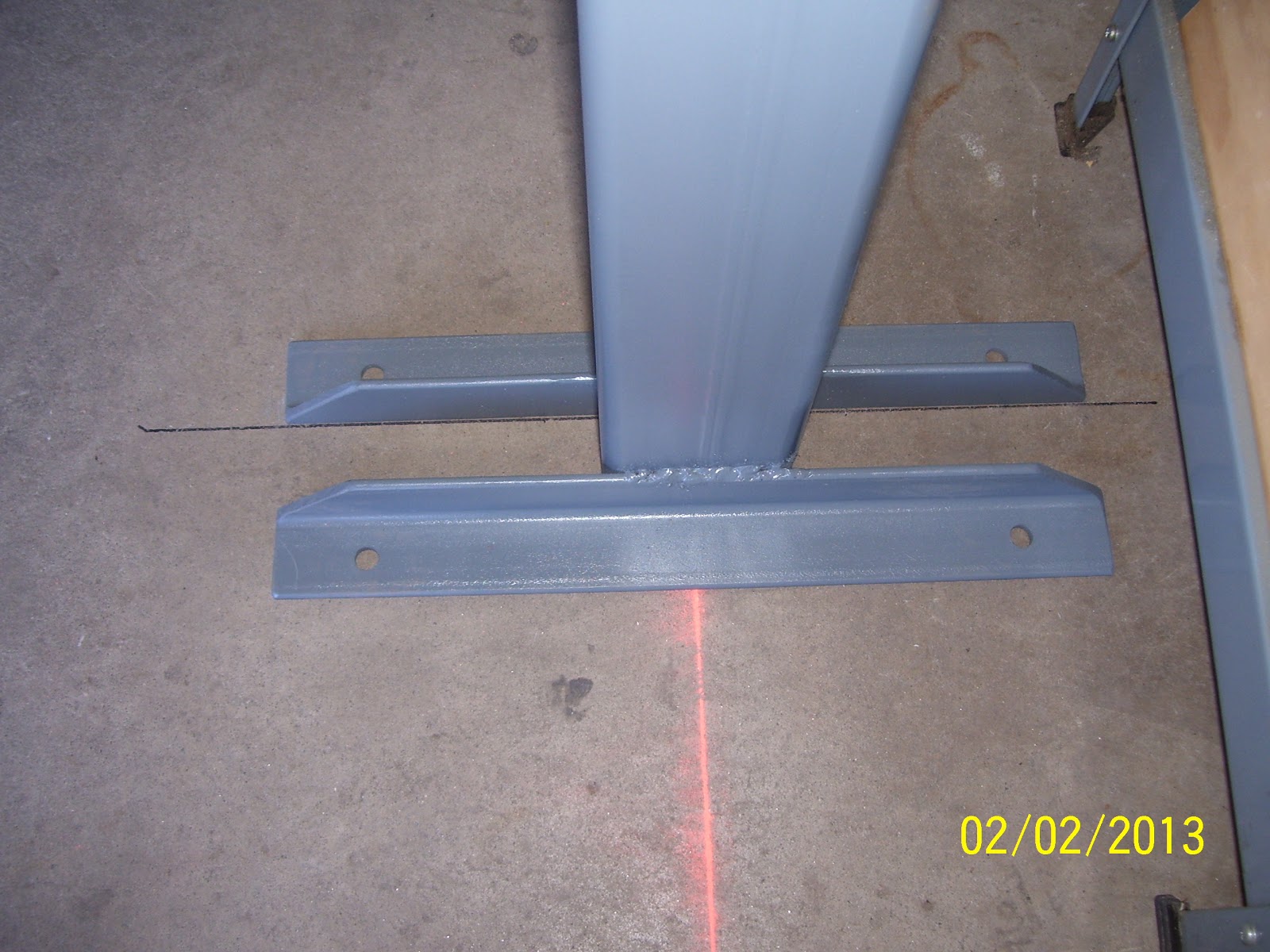
Well the day finally came to drill some holes in the concrete and bolt the wing stand down. What better day then Super Bowl Sunday to work out in the shop, especially with the weather at a balmy 60 degrees. What you won't see in the pics is the large amount of time spent yesterday forming a large number of flat metal shims out of 1/8 inch thick strips of steel. This proved to be avery challenging exercise, and as I have mentioned in previous posts I pretty much figured that it would be, since my concrete floor in the garage is less than acceptable for doing anything that requires a "flat" surface.
I literally had to trial fit each stand, measure the distance between them, and check the wobble of each one and then figure out the best method of shimming each one up to remove the wobble. That process really sucked, but I managed to get it done. The only thing I was concerned about was ensuring that the 114 inches of space between the inside edges of both stands for each wing was retained. I quickly found that without the shims in place that each stand was leaning inward bit, so I was losing my 114 inch distance the higher up the stand that I measured. Anyway, I cut out several pieces of metal for 3 out of the 4 stands. One of them did not need much shimming at all, so that was good. Only problem was that it still required shimming on one side only, but the 1/8 inch shims were too thick for what I needed. I ended up using a piece of .032 aluminum from my trim bundle that I had used as a test piece for the 2 part epoxy primer I started using on the wings a long time ago. This seemed to do the trick.
Anyway, it all started with determining general placement of the stands. This involved clearing the refrigerator and freezer door travel, and, most importantly, allowing enough room for getting both cars in the garage with both wings on both stands. After this general placement was figured out, I snapped some straight lines with a chalk line, as shown below:
The stands in front of my work benches were the most challenging, because there is a separation or relief line where additional sections of garage floor were added by the previous owners of this house when they decided to make the garage larger than originally designed. I am glad that they decided to make the garage a bit larger, but I just wish that they would have re-poured the entire floor after they did it. As it is, the position of the wing stands straddles both sides of this stress relief line, so I am mounting one of the stands on two separate pieces of concrete. What a pain, not to mention a shimming nightmare.
Here is shot of the line I am talking about. The stands pretty much needed to go in this position because I needed enough room in front of the work bench to allow for working on ailerons and flaps and other work, and at the same time I had to position them so I could still get the cars in the garage. So that is why they ended up where they did. The best position for allowing other work on the benches and gettting the cars int he garage turns out to be about the worst position one might choose to mount something like this. Oh, well, par for the course for me I guess. Nothing is easy.
After the positioning and the chalk line, I used a sharpee with a thick tip to draw the outline or at least the critical lines for marking the position of each stand so that it would meet the 114 inch spacing per the plans.
Here are some tools of the trade used for the above tasks. I used the square to draw the sharpee lines so that they were exactly perpendicular to the snap line.
And here is the line for the stands along the right side of the garage. Yes, with this setup, I can still get both cars in the garage.
And here is just one example of the wacked out shimming job I had to perform. Note that the only thing I was concerned about was stability of the stands after being bolted to the floor so that they would maintain the 114 inch distance between the posts. I was much less concerned about the "level" attitude of the stands along the other plane, since the shelf assembly will be adjustable for level, so I can offset any leaning of the posts by adjusting the screw bolt so that the shelf will be level. At its worst the posts are about 1/4 inch to 3/8 inch off level, and I think the threaded rod will take care of that with no problem. Had I decided I wanted the posts perfectly level in all planes of existance I would certainly not be here writing about the experience now, because I would still be out in the garage trying to get everything perfectly level. Sometimes you just have to settle for less.
The above pic shows the anchors installed and the nuts torqued down to spec. The process I used to drill the holes was to use a rotary hammer drill with a six inch long 3/8 inch cobalt bit that I rented from HD. I drilled the holes with the stands in place, thanks to my trusty son Adam who held them in place while I drilled the holes. This was largely a non event, and I was quite surprised at how easily the drill cut through the concrete. Only problem is that for some reason one out of the 16 holes I had to drill either did not get cleaned out properly, or the concrete failed underneath, or the bolt anchor got messed up, or something, but it would not seat in the hole and would not grab the concrete. SO as a result I have one anchor that is unable to secure anything on one of the stands, so I will ahve to rely on the three good bolt anchors to keep that stand in place.
After all the bolts were torqued down, I check each stand for security, and I am not concerned at all about any of them ever moving so much as a muscle. They are all solidly mounted to the floor. Now I just have to drill the holes for the shelf hardware, threaded rods, and bottom trailing edge supports, adn cut the 1 1/4 inch angles to size and drill some more holes in those. As the saying goes, 90% done and 90% left to go.....
Here is the drill I used and the air tool I used to clean out each hole after it was drilled.
Many thanks to son Adam for his assistance today. While I am discouraged by the amount of time and effort I have had to expend on just meer fixtures, I am pleased that things finally look like they will be in place to allow me to meet or exceed my goal of getting both the wings about 95% done by the time Oshkosh 2013 rolls around.
I literally had to trial fit each stand, measure the distance between them, and check the wobble of each one and then figure out the best method of shimming each one up to remove the wobble. That process really sucked, but I managed to get it done. The only thing I was concerned about was ensuring that the 114 inches of space between the inside edges of both stands for each wing was retained. I quickly found that without the shims in place that each stand was leaning inward bit, so I was losing my 114 inch distance the higher up the stand that I measured. Anyway, I cut out several pieces of metal for 3 out of the 4 stands. One of them did not need much shimming at all, so that was good. Only problem was that it still required shimming on one side only, but the 1/8 inch shims were too thick for what I needed. I ended up using a piece of .032 aluminum from my trim bundle that I had used as a test piece for the 2 part epoxy primer I started using on the wings a long time ago. This seemed to do the trick.
Anyway, it all started with determining general placement of the stands. This involved clearing the refrigerator and freezer door travel, and, most importantly, allowing enough room for getting both cars in the garage with both wings on both stands. After this general placement was figured out, I snapped some straight lines with a chalk line, as shown below:
The stands in front of my work benches were the most challenging, because there is a separation or relief line where additional sections of garage floor were added by the previous owners of this house when they decided to make the garage larger than originally designed. I am glad that they decided to make the garage a bit larger, but I just wish that they would have re-poured the entire floor after they did it. As it is, the position of the wing stands straddles both sides of this stress relief line, so I am mounting one of the stands on two separate pieces of concrete. What a pain, not to mention a shimming nightmare.
Here is shot of the line I am talking about. The stands pretty much needed to go in this position because I needed enough room in front of the work bench to allow for working on ailerons and flaps and other work, and at the same time I had to position them so I could still get the cars in the garage. So that is why they ended up where they did. The best position for allowing other work on the benches and gettting the cars int he garage turns out to be about the worst position one might choose to mount something like this. Oh, well, par for the course for me I guess. Nothing is easy.
After the positioning and the chalk line, I used a sharpee with a thick tip to draw the outline or at least the critical lines for marking the position of each stand so that it would meet the 114 inch spacing per the plans.
Here are some tools of the trade used for the above tasks. I used the square to draw the sharpee lines so that they were exactly perpendicular to the snap line.
And here is the line for the stands along the right side of the garage. Yes, with this setup, I can still get both cars in the garage.
And here is just one example of the wacked out shimming job I had to perform. Note that the only thing I was concerned about was stability of the stands after being bolted to the floor so that they would maintain the 114 inch distance between the posts. I was much less concerned about the "level" attitude of the stands along the other plane, since the shelf assembly will be adjustable for level, so I can offset any leaning of the posts by adjusting the screw bolt so that the shelf will be level. At its worst the posts are about 1/4 inch to 3/8 inch off level, and I think the threaded rod will take care of that with no problem. Had I decided I wanted the posts perfectly level in all planes of existance I would certainly not be here writing about the experience now, because I would still be out in the garage trying to get everything perfectly level. Sometimes you just have to settle for less.
The above pic shows the anchors installed and the nuts torqued down to spec. The process I used to drill the holes was to use a rotary hammer drill with a six inch long 3/8 inch cobalt bit that I rented from HD. I drilled the holes with the stands in place, thanks to my trusty son Adam who held them in place while I drilled the holes. This was largely a non event, and I was quite surprised at how easily the drill cut through the concrete. Only problem is that for some reason one out of the 16 holes I had to drill either did not get cleaned out properly, or the concrete failed underneath, or the bolt anchor got messed up, or something, but it would not seat in the hole and would not grab the concrete. SO as a result I have one anchor that is unable to secure anything on one of the stands, so I will ahve to rely on the three good bolt anchors to keep that stand in place.
After all the bolts were torqued down, I check each stand for security, and I am not concerned at all about any of them ever moving so much as a muscle. They are all solidly mounted to the floor. Now I just have to drill the holes for the shelf hardware, threaded rods, and bottom trailing edge supports, adn cut the 1 1/4 inch angles to size and drill some more holes in those. As the saying goes, 90% done and 90% left to go.....
Here is the drill I used and the air tool I used to clean out each hole after it was drilled.
Many thanks to son Adam for his assistance today. While I am discouraged by the amount of time and effort I have had to expend on just meer fixtures, I am pleased that things finally look like they will be in place to allow me to meet or exceed my goal of getting both the wings about 95% done by the time Oshkosh 2013 rolls around.
Subscribe to:
Posts (Atom)