these pics are year a year and half old, but the pics of the mods I performed may still help somebody else along the way, especially if the quality of any substantial products starts to go way down due to COVID impacts, as I have already witnessed many times. The simple fact is that even for those companies that are still in operation, many of them are working with reduced staff or have experienced reductions in their labor force, and so the number and quality of those products may suffer as result. Unfortunately, The RIGID 14 inch band saw suffered from many quality problems long before COVID. Thankfully there were some things you could do to help solve many of the problems and make it a almost first-rate tool.
First was replacing the stock black rubber tires, which required removing both wheels from the saw. You have to completely disassemble the table, guides, and saw blade, but it wasn't too difficult to do: I found and ordered some orange colored neoprene replacement tires. removing the old tires was easy because they were horribly cracked and deteriorated. These needed to go away because they are hard rubber that develops uneven ridges over time, and this contributes to the vibration of the saw. The new tires are softer so they absorb vibration better, and the blade also tracks better. The hard part was getting them on each wheel. When done, they looked like this:


In the last pic you can see that the width is slightly less than the entire width of the track. This was the result of my over-aggressive sanding of the edges of the tires. This was necessary because the width of the metal track of each wheel is about 7/8 inches, but the tires only come in a 1 inch width. I spent quite a bit of time reading others posts about this. Some tried fitting it "as is" but it does not sit properly in the tire track, and others tried cutting the width with a utility knife. Neither of these methods worked very well, if at all.
Finally somebody came up with a way to fairly accurately reduce the width of the tires by sanding them down. However, this method still required some careful preparation. Basically you had to fashion a piece of wood long enough to support the tire, and with a 7/8 inch width. then you had to put the tire over the wood, clamp it down tight so that the remaining portion of the tire extended beyond the wood width, and then you carefully run it on your belt sander. Here are the pics and the number of tools involved:
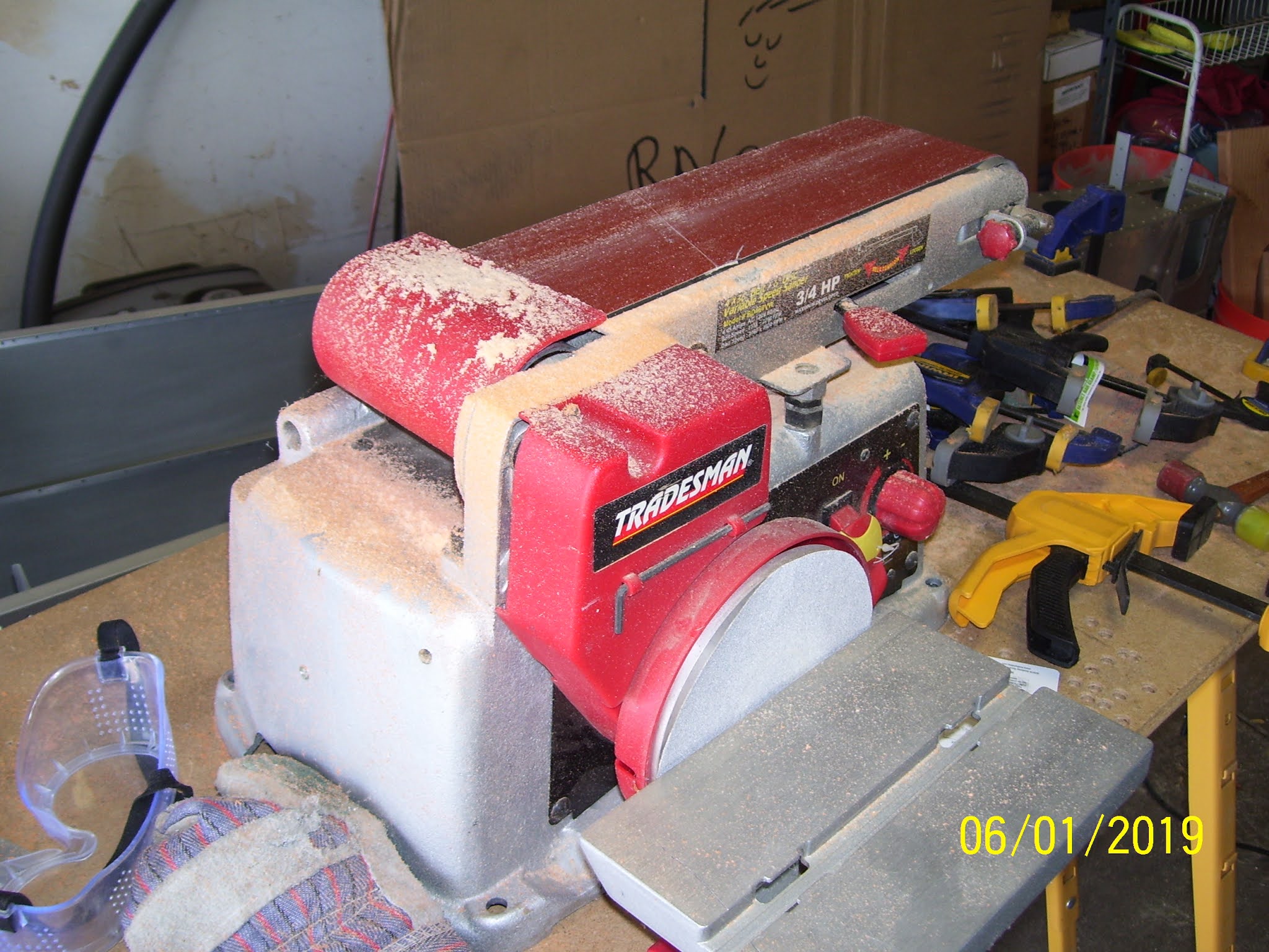


the tricky part about this was not being too aggressive with the sanding and checking your progress often. The sander only reached so far, so you had to do 2/3 of it on one side and then turn it around to do the remaining portion. The idea was to keep sanding until the width of the tire was reduced to the correct depth, and stop sanding before you started to sand away the wood. The above pic does not show the tire all clamped up, which was the other difficulty. but when you hit the sander the tire is wrapped around the wood and clamped in numerous pace to keep it from moving. The hardest thing about the the clamping was being able to clamp it securely but leave enough clearance to allow the tire material to be removed by the sander without also removing material from your bar clamps. The assembly became quite heavy and unbalanced after all the clamps were applied, so this part was a bit challenging. As I stated previously, mine were a little over done, but they still seem to serve their purpose well and do not cause the saw blade or tire to move as long as proper tension is maintained on the blade.
The next big task was disassembling the saw from the stand so that a 3/4 inch piece of plywood could be fashioned that the motor and the saw would both rest on. One of the biggest causes of vibration of this saw was the hard rubber feet that the motor mounts sat on. The fix was to completely remove the rubber feet and mount the motor on the plywood. This fix also required some longer mounting bolts, and there were several vent holes in the metal stand that also had to be transferred and re-created in the plywood base. Cutting the board to size was easy. Cutting those vent slots mounting bolt slots - not so much.


Next was to reassemble the saw and motor with the new plywood stand, re-install the wheels and balance them. The wheels on this saw were notoriously unbalanced. I followed the procedures to determine the unbalanced areas, and used self sticking pinewood derby lead weights with epoxy glue to mount them to the correct locations on each wheel.


Then came the replacement link belt from Harbor Freight, which replaces the hard rubber belt that came with the saw. This further reduces vibration because the rubber belt develops a memory as it wraps around the pullies of the motor and the bottom wheel. This causes a bump in certain locations in the belt that adds to the vibration.

The links are removeable to get the correct belt length, but it is quite the jigsaw puzzle to figure out how to do this. The other problem was not clearly understanding which way the links needed to be oriented on the pullies. After a while I found pics that clarified this. Operation of the saw confirmed that I had them positioned correctly.
The last mod was to replace the stock, metal saw blade guides with a composite product called Cool BLocks. These keep the temp of the blade down. which results in more efficient cutting and longer life of the saw blade.


And finally my math to figure out the width of the wheels and the new tires and how much I needed to remove, using a digital caliper:

And finally the packaging for the replacement tires I purchased. Once all these changes were completed I put the saw back together, did the nickel test, and the difference was like night and day. No this saw runs much more smoothly, and I can trust it with finer cuts for the airplane parts that it will be making. I also bought a rolling stand set from HF that I have not installed on it yet. Once I put my new shed together the saw will go in there, and I will be able to move it around easily on this new stand.

This was the last thing I worked on that had anything to do with the plane over a year and half ago.
Next up, went back to HF to purchase the 1000 lb engine stand that many other RV 8 builders have used to fabricate a rotissorrie for the QB fuselage to aid in numerous tasks with assembling parts, panting, and mounting the landing gear, etc. And yes, you have to fabricate more parts to complete this project, but it is not ear as difficult as fixing the bandsaw was.
KPR
No comments:
Post a Comment