Anyway, to pick up where I left off, I had one last chapter in this whole removeable section fabrication to cover before I move on to what I was finally able to get done today. After finally getting a part sized, trimmed, fitted, and drilled with correctly positioned mounting holes to #30, I now needed to make a template. The problem was that the part that I was finally happy with had been fitted to the LE, and as a result it was now slightly curved, and this presented some problems with trying to fabricate a new plat piece of metal out of another slight curved piece of metal.
As a long story short, I decided that I could probably use some weights to re-flatten the "good" part just enough for me to draw a matching pattern onto a piece of .025 flat metal again, just as I had done to make the part that I have finally deemed "good." the big deal about all this was trying to take advantage of the precut "factory" edges of the new metal, because their cutting machines and processes are much more accurate than mine. I wanted to do this so that at least two of the edges would be absolutely straight. This minimizes any additional work I need to do to trim and shape the other two edges to get a good fit. The other issue is to ensure that the holes are drilled in the correct spots, and that the curves in each of the four corners are radiused correctly.
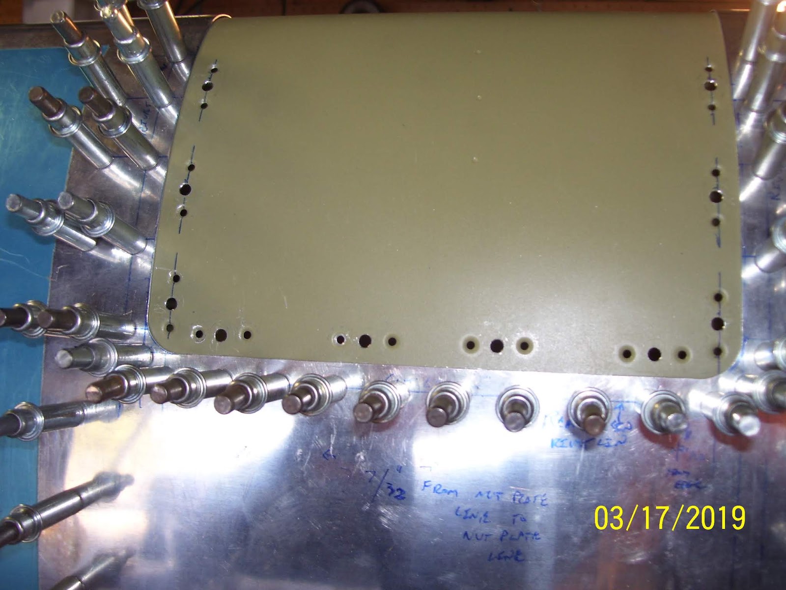
At the end of it all, it made me really appreciate metal parts that are precision cut, punched, and fabricated by precision tools. What follows is a series of pics showing how I went about making the template from which I would be able to make as many more of these as desired. First up was a process of taking the now partially bent "good" part and setting into position against the two good edges of the .025 sheet using some cleco clamps and my bucket of very heavy #40 clecoes. This did a pretty good job of flattening the part back down so that I could trace the edges onto the new sheet and also match drill the holes around the perimeter.

This turned into a very involved exercise of precise clamping and drilling, moving things around as necessary and re-clamping again. I used the wood from my drill board to match drill the holes and then cleco both parts directly onto the drill board.

After it was all done the holes were deburred and the top and bottom and edges were marked, and it was cut from the sheet using either shears or my Dremel tool cutoff wheel. The problem with this next one is that I ended up trimming to much material away from the corners and edges and so this one did not fit very well and I had to make yet another one.

So I ended up making another one where I intentionally added a bit more material on the edges to ensure that I would not come up short. So after making 3 more of these crazy things I finally ended up with a keeper that I could use for flat template that could be used to accurately make more of them as necessary. Trimming the corners to have just the right radius is also a challenge.
Here are some pics of the horrible trimming job I did tht forced me to have to make yet another template:


SO now we can fast forward to today. The problem was that I could NOT continue with anything on the LE until had this template made correctly, because the next step in this process was to upsize each of the #30 holes in the good part to #19 for the #8 dimples and screws that will be inserted into them to attach the part to the subskin.
So with a "good enough" template now completed, I reattached the good part to the LE and then re-clecoed the LE skin securely onto the wing spar to make certain that everything was in the proper position before drilling the holes. Then I took the #19 drill bit and started upsizing each of the #30 holes in the removeable section as well as the subskin underneath. I used the black colored clecoes to secure the section to the subskin as I went. I had 20 holes to upsize and only 10 clecoes, so I had to be creative about how I did this. I upsized all the holes on the top side of the LE first, followed by the bottom holes. Then I used my deburring bit and my edge deburring tool to ensure that the holes were very clean and smooth, just as I had done for the tank attach holes long ago, so that the #8 dimples would not have any cracks in them.
Here are pics of the top and bottom sides after the holes had been upsized and the removable section was removed. the #40 holes for the rivets that will hold each nut plate were already drilled and dimpled long ago, so this exercise is just for the 20 (10 top and 10 bottom) center screw holes.

And here are the top and bottom side pics of the removeable section after I dimpled all the holes on both sides


I was glad that all the dimples seem to have come out well. While setting the dimples in the removeable section was relatively easy since it is not bent very much, forming the #8 dimples on the subskin turned out to be yet another interesting exercise to set these dimples. It required using both hands and my head to position each hole over the male dimple die in my C Frame and keep the metal away from the ram, so that I could use the ball peen hammer to set each dimple by whacking it a few times. Just as when I previously set the dimples for the tank attach nutplates on the subskin several months ago, the holes nearest the front of the subskin closest to the bend were the hardest to set.
With the dimples on the removeable section done the next step was to remove the LE from the wing spar for what I hope is the absolute FINAL time before I permanently affix it to the wing spar, and remove the subskin so that I could set those dimples as described above. This also went reasonably well, despite the awkward contortions of my hands and head required to set them.
I also took a pic of the new "final" flat template, and the label I wrote on it to ensure that I would be able to tell months from now that I would be able to to tell which template is the "good" one as I proceed to create the same thing for the right wing LE. However since I doubt that I will end up with everything sized exactly the same on the right wing, I think I will end up making a customer one for the right wing as well, when the time comes.


With all the #8 dimples done, it was time to cleco the K1100-8 nut plates in place on the subskin s I could start riveting those in place. I did not quite get to that today, so that will be my next task that I will hopefully complete next week. Here is the subskin with all the nut plates clecoed into position:


No comments:
Post a Comment