The first task was to figure out a way to ensure that the cut line was symmetrical from the top of the LE, and all the way around the front to the bottom side. Previously I had measured and drawn the straight lines on the top and bottom sides of the LE where the outer skin will be cut to make way for the new modular, removable LE component. However, I had not continued the cut line all the way around the very front part of the LE to connect the lines on the top and bottom sides of the skin.
Since the wing has no taper to it, and it is all one consistently straight edge from the inboard of the wing all the way to the wing tip, and the curvature of the LE also remains consistent, the cut lines that I had drawn on the top and bottom sides of the LE skin should line up with each other as the line is extended around the very front curved part of the LE, connecting both lines together. The problem was how to draw a straight line on a curved surface that connects the other straight lines together.
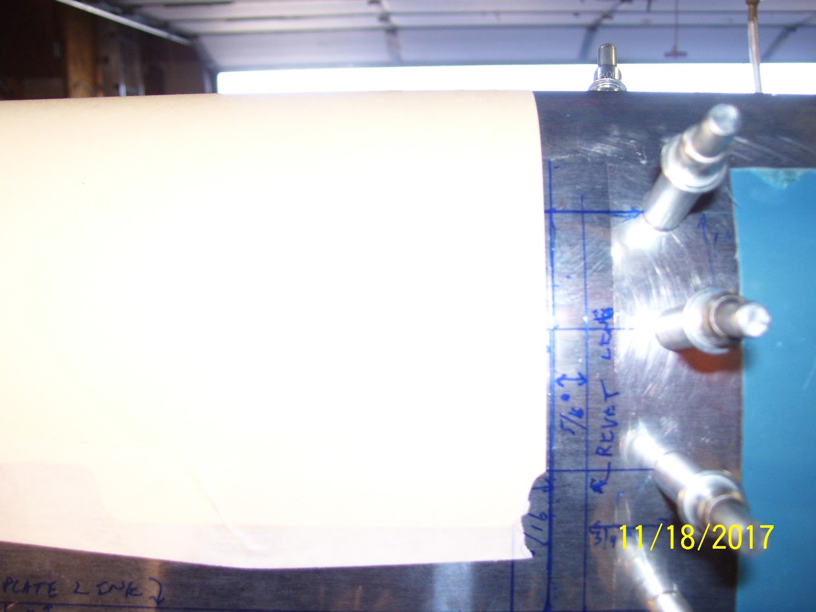
While there were several options for doing this, I decided to use half of a piece of file folder paper. this is thick enough to provide a small straight edge, straight enough because the edges of the folder are precisely cut square and straight, and flexible enough that it will hold its shape as it wraps completely around the curve of the LE. It can then be taped into place, and the lines from either side of the LE can be extended around the curve and over to the line on the other side.
If my measurements were done correctly, this method should result in the top and bottom lines connecting seamlessly together when the line is drawn around the curve, following file folder edge. the actual results were close, but not as close as I would have liked. The following series of photos shows the straight edge of the file folder lined up with the cut line on the top of the LE, taped in place at the bottom with masking tape, then wrapped around the curve of the LE, and taped into position on the bottom side.


If I do this, then I am confident that when I draw the connecting lines the next time they will all line up as expected. This is why you always try to measure many times, and cut only once, to make certain that everything is laid out exactly as it is supposed to be. If I screw up here and cut too much material away in the wrong spot, I can't get it back, and months of work will be ruined.
Next, it was time to remove the fuel tank and get back to the Z-brackets. As I began this session I realized that the Z Brackets for the left fuel tank had not been positioned or removed from the wing spar since 2014. They have been temporarily bolted into position all this time. An odd feeling came over me as I realized that, because had I decided just to continue with the steps to do a stock build, and NOT undertake this modification, I would have removed the Z brackets for the next step in the process a long, long time ago.
The basic goal was to mount nut plates on 6 of the 7 total nut plates where they had been temporarily secured to the wing spar with lock nuts so that the rear fuel tank baffle plate could be positioned and the rivet holes for the bracket-baffle-tank ribs could be drilled. Now that this task had been completed, it is time to drill the necessary rivet holes for the nut plates that will go on most of the Z brackets for the bolts that will attach each bracket to the wing spar. The only way to do this is to remove the Z-brackets from the wing spar.
I found that using a 3/8 open end wrench on the lock nuts to hold them in place, and a small 1/4 inch screw-driver-like ratchet driver on the bolt heads on the bottom of the wing spar to remove the bolts, was the easiest way to do this. In fact, I think this is precisely the way that I attached them over 3 years ago.
Here is a pic with the bolts for all 7 brackets removed. Important to note here is that I made sure that top, bottom, and position of each bracket was remarked with a Sharpee on the upper flange of each bracket. I did not want to go through another episode like I did with the LE ribs where two of them became out of sequence and were installed in the wrong location, causing issues. So I made sure each Z bracket was clearly marked to avoid the same confusion.


In order to do so many nut plates, the question becomes how to do this efficiently and quickly. The good news is that all the bolt holes have been drilled and reamed a long time ago. That exercise was painful enough. I decided to use the same method that many other builders have used, by taking a "throw away" K1000-3 nut plate, and run a standard 10-32 tap through the bolt hole to widen it and allow the bolt to be threaded on it much quicker and easier. This allows you to use a "throw away" AN3-4 bolt and washer that can be quickly threaded onto the nut plate, which will serve as a drill jig of sorts for drilling all of the #40 rivet holes for each nut plate on each Z bracket.
Nut plates are designed at the factory to have a slightly squashed bolt hole so that the threads of the bolt remain tightly secured. You do NOT want to use a tap to loosen these nut plate holes on the ones you intend to permanently install, because you will lose the gripping strength. This is especially important for structural applications. While others may argue, I tend to believe that the bolts and nut plates holding each of the fuel tank brackets to the wing spar are "structural" in nature, so these have to be tightly secured. That is why you sacrifice a nut plate and a bolt for this operation. Once this has been completed, the bolt and the nut plate should be discarded, or placed in a junk drawer where they should remain completely separated from the "good" hardware.
Here is an untapped stock nut plate. You can see the slightly ovalled shape of the thread shaft in the middle. Bolts are actually EXTREMELY hard to thread onto these nut plates.


Those will have to wait until tomorrow. Then I probably have some primer prep work to do before I rivet the nut plates onto the Z bracket. Other than that, once I get some confirmation of the integrity of my plans to cut the LE and apply the necessary rivets and nut plates, I will be ready to do that. If I get held up on the LE stuff I can at least keep going on the fuel tank. Since it is back in the cradle now I can start match drilling all the rivet holes, fabricating the stiffeners, drilling the screw attach holes out to #19 and dimpling them and the joiner plate attach holes for a #8 screw, etc., etc. There is no shortage of stuff to do - that's for sure!
All for now.
KPR
No comments:
Post a Comment