To catch up a bit, lots of text and and no pics for the past few posts, so here are some pics....
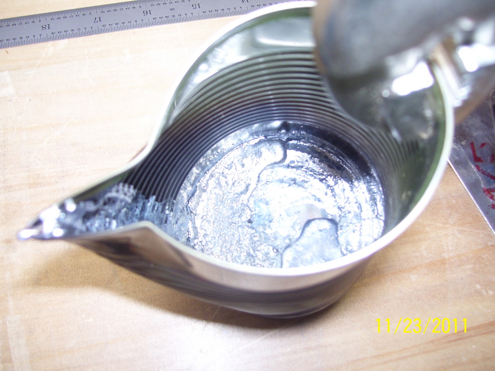
First is my smelting pot - the olive can bent into shape foe melting/pouring the lead:


This is the inboard side of the trim tab, marked 1/8 inch inboard of the true cut line. I ended up cutting the tabs off right to the cut line and deburring them on the scotch brite wheel. Two hands on the dremel tool adn careful cutting here.... Really trying hard to make this a one-trim-tab effort.

Next is the line to cut the tabs off of the elevator. There is some detail about this in the plans worth mentioning here. Question is where do you decide to draw the line, and based on what reference? Answer is that the plans say to place a square angle up against the trailing edge of the elevator where it is cut out for the trim tab, and draw a line perpendicular to that line for the "bend" line (in my case it is a "Cut" line). All fine and good, but you still don't know exactly where to draw the line - without carefully revewing the plans that is.
What I did is measured the length the trim tab skin at the leading edge - came out to about 17 and 22/32 inches. I then transferred that measurement from the inboard trailing edge of the elevator, outward that same distance, and made a mark. I then took the square, aligned it with the TE of the elevator, and drew the line across the tab on that mark.
This should allow the skins from the elevator and the trim tab to just butt up against each other, but you don't know for sure until you get the trim tab clamped into place.


Back to the plans to sort this out - Van's calls for a MINIMUM gap between the trim tab and the elevator of at least 3/32 inches to prevent the possibility of the two components from binding while under normal flight loads. So when I add that distance to my original measurement, it then looks much closer to the bend line I see in other builders logs. My approach was to go ahead and cut the tabs off the trim tab skin flush to the outside edges, since this is the final bend line that is called out in the plans for the trim tab. I then left a healthy amount of excess material on the elevator so that I can trim it up only as necessary once I start fitting the trim tab in place to achieve the optimal 3/32 inch clearance. Don't want to cut too much off and end up with too wide of a gap, which will add drag and not look very professional either. This is actually another plus for choosing to install the riblets instead of bending the dreaded tabs, because you can cheat a bit by moving the webs of the riblets on both the elevator and trim tab in or out to create the correct gap. Just have to be sure to maintain proper edge distance for the rivets that will insert into the flanges of each riblet.
How did I cut the tabs? I used the dremel tool and the reinforced cutoff wheel just as before:

First cut finished, next step is final cut and debure the edge so it is flush with the edges on both ends of the tab.

Pieces after the initial cut was performed


Next you can see the inboard bottom trim tab edge, all cut and deburred, with the trim tab servo push rod control horn clecoed into place. This is the attach point of the clevis from the trim tab servo to the trim tab that will make it go up and down.

Note the top of the pic where the clevis and the attachment pin have been inserted into the hole at the front of the horn. I also deburred this hole but did NOT run a drill bit through it. The last thing you want to do here is to enlargen the hole where the clevis pin is inserted. You do NOT want excessive play here or it may lead to problems trimming the airplane later on. Some folks choose to insert a cleco in here as well. I chose not to do that either. The clevis pin needs to just fit inside the hole adn be somewhat snug, but not binding
Lastly, here is a pic of the flop tube I received in a previous parts order from Van's:

I then studied the plan diagrams that show the plumbing of the fuel system into the fuselage. I now think I have a fairly clear understanding of how the fuel pickup lines and vent lines are routed through the fuselage from the wings. Amazes me how many 90 degree bends there are in the lines and fittings. If I did that in a 2 cycle RC airplane engine it would not stand a chance without some type of pump system in place. I guess the RV is the same way, in that I think it will have three fuel pumps installed - 1 auxiliary pump for each tank, and the engine driven fuel pump.
Hoping that my parts arrive today - Black Friday. Next steps are to drill and coutersink the trim tab front spar, elevator rear spar, prime the inside of the trim tab skin, bend the trim tab skin TE, align and drill the holes in the piano wire hinge, and fabricate the three riblets. Lots of stuff to do, but none of it overtly time consuming. Also read up on the hinge placement. Turns out to be another area where Van's is severely lacking in detailed info about this. A lot of confusion about how to mark the holes in the hinge, and the sequence of drilling, dimpling, and countersinking that must be done in the correct order to get it right. Study every detail in the plans, think it through, and it should come together just fine.....
No comments:
Post a Comment