Tuesday, March 19, 2019

Started Riveting the Nutplates for Securing the LE Removeable Section to the Subskin

I started out by free-handing the attach rivets for the first couple of edge nutplates on the subskin with the pneumatic squeezer, but even though I was able to set these OK, I did not like the risk and the inability to hold that beast of a heavy squeezer with only one hand while holding the subskin in the other. So before I set any more rivets, I had to rig up another custom method of clamping the subskin to allow the proper support and positioning of the part for riveting the nutplates on. Here is the initial setup using my padded 4x4 wood blocks (3 of them) and the bar clamps similar to what I have done before:
I had to reposition and reclamp the part for each new rivet, sliding the subskin as close as I could get it to the clamped blocks without causing interference between the squeezer and the clamps. I also added a second clamp on the other side to tighten up the structure. This allowed me to use both hands on the squeezer to set the rivets.

I used my 3 inch yoke which had enough clearance from the edge of the subskin to set all of the edge rivets on both sides. The 4 remaining nutplates on the rear edge of the top and bottom of the subskin will have to be bucked - oh boy - there is something I have not done in a while. 
Also shown in the above pic are the flat rivet sets that I used. The thing I hate about nut plates is that the rivets that attach them are on either side of the center shaft for the screw. This does not leave very much room for positioning the rivet sets so as to be centered over the rivet shaft without being too far over to one side to ram into the screw thread shaft, thus destroying the nutplate. ON the other side of the nut plate exists the possibility that you could slide too far away from center, causing an incorrectly set shop head on the rivet. IN order to avoid hitting the screw shaft, I needed to use a 3/8 inch wide flat set (on the top of the yoke in the above pic), and the 1/2 inch wide flat set on the bottom which goes over the manufactured head of the rivet. This means that the squeezer must be positioned as centered as possible to avoid either condition described above.  And may I say that it is a royal pain in the ass having to use a flat set that is that small to do all the mashing of the shop head. 

Lets just say that so far I have had to drill out about 4 rivets because of this, and I may have to replace one nutplate after damaging the edge of it when the squeezer slipped while squeezing, to the point that I am not happy with it. The other thing that sucks about this session is that I cannot position the squeezer very easily in such a way that I am able to pull against the manufactured head with the top of the yoke, so that the ram that moves from the bottom does not displace the part or cause the squeezer to slip out of position as it travels upward. Instead I have to keep the extremely large squeezer body on the outside of the part, which forces me to do the opposite by placing the moving ram on the manufactured head of the rivet instead of the shop head. The result so far is 4 badly set rivets that needed to be drilled out and replaced. 

The good news is that I was able to set almost all of the edge nutplate rivets on both sides of the subskin using the pneumatic squeezer. And the rivet heads seem to be pretty flush on the subskin surface where the removeable section will be sitting on top of them, so I was happy about that as well. Here is the result of one side of the edge nut plates installed:
I should also mention that I used my rivet gage to determine the size of the rivet that I needed - the winner was AN426AD3-4 rivets, These set very nicely in the dimpled nutplate flanges and left more than enough of a correctly sized shop head. 
You can tell that I have riveted anything in a while, because I also forgot one other cardinal rule that I had established long ago when using the pneumatic squeezer to set the rivets. The instructions for this tool say to set it to 90 psi, but  found that this tool has just too much force at that setting, and this can cause the tool to shift out of position or ram with such force that it almost damages the part. So I found long ago that setting the air pressure to 75 psi works a lot better. It does not activate as violently as it does at 90 psi, and it still maintains enough force at that settings to more than adequately set AN426 rivets.  Here is a shot of the air pressure setting for posterity later on.
Another shot of all the clamps in position
And finally a shot of a successfully set nut plate using this setup. I made it all the way to the last rivet on the last edge nutplate and managed to screw that up because I got too fatigued and wanted to finish it. So I drilled that one out and will reassess that one tomorrow. Then I will need to come up with yet another custom clamping setup so that I can buck the remaining rivets on the remaining nutplates  When that is done, the subskin goes back into the LE skin for the final time, where all those millions of dimples will also be riveted together into a solid LE with all the custom work completed.


Sunday, March 17, 2019

Round 3 - Making a Template of the Removeable Section of the LE

yup - another round of lousy weather, delays - yada yada yada has yielded very little work on the project in over a month. It's been way too cold to work in the garage, and we just experienced a lovely thing that some moron decided to call a bomb cyclone several days ago that resulted in our first real blizzard in the Denver area in a good long while.

Anyway, to pick up where I left off, I had one last chapter in this whole removeable section fabrication  to cover before I move on to what I was finally able to get done today. After finally getting a part sized, trimmed, fitted, and drilled with correctly positioned mounting holes to #30, I now needed to make a template. The problem was that the part that I was finally happy with had been fitted to the LE, and as a result it was now slightly curved, and this presented some problems with trying to fabricate a new plat piece of metal out of another slight curved piece of metal.

As a long story short, I decided that I could probably use some weights to re-flatten the "good" part just enough for me to draw a matching pattern onto a piece of .025 flat metal again, just as I had done to make the part that I have finally deemed "good." the big deal about all this was trying to take advantage of the precut "factory" edges of the new metal, because their cutting machines and processes are much more accurate than mine. I wanted to do this so that at least two of the edges would be absolutely straight. This minimizes any additional work I need to do to trim and shape the other two edges to get a good fit. The other issue is to ensure that the holes are drilled in the correct spots, and that the curves in each of the four corners are radiused correctly.

At the end of it all, it made me really appreciate metal parts that are precision cut, punched, and fabricated by precision tools. What follows is a series of pics showing how I went about making the template from which I would be able to make as many more of these as desired. First up was a process of taking the now partially bent "good" part and setting into position against the two good edges of the .025 sheet using some cleco clamps and my bucket of very heavy #40 clecoes. This did a pretty good job of flattening the part back down so that I could trace the edges onto the new sheet and also match drill the holes around the perimeter.
This turned into a very involved exercise of precise clamping and drilling, moving things around as necessary and re-clamping again. I used the wood from my drill board to match drill the holes and then cleco both parts directly onto the drill board.
After it was all done the holes were deburred and the top and bottom and edges were marked, and it was cut from the sheet using either shears or my Dremel tool cutoff wheel. The problem with this next one is that I ended up trimming to much material away from the corners and edges and so this one did not fit very well and I had to make yet another one.
So I ended up making another one where I intentionally added a bit more material on the edges to ensure that I would not come up short. So after making 3 more of these crazy things I finally ended up with a keeper that I could use for flat template that could be used to accurately make more of them as necessary. Trimming the corners to have just the right radius is also a challenge. 

Here are some pics of the horrible trimming job I did tht forced me to have to make yet another template:


Yeah they are blurry but you can still see how bad the gaps are. This was just not acceptable so I started over.


SO now we can fast forward to today. The problem was that I could  NOT continue with anything on the LE until had this template made correctly, because the next step in this process was to upsize each of the #30 holes in the good part to #19 for the #8 dimples and screws that will be inserted into them to attach the part to the subskin. 

So with a "good enough" template now completed, I reattached the good part to the LE and then re-clecoed the LE skin securely onto the wing spar to make certain that everything was in the proper position  before drilling the holes. Then I took the #19 drill bit and started upsizing each of the #30 holes in the removeable section as well as the subskin underneath. I used the black colored clecoes to secure the section to the subskin as I went. I had 20 holes to upsize and only 10 clecoes, so I had to be creative about how I did this. I upsized all the holes on the top side of the LE first, followed by the bottom holes. Then I used my deburring bit and my edge deburring tool to ensure that the holes were very clean and smooth, just as I had done for the tank attach holes long ago, so that the #8 dimples would not have any cracks in them. 

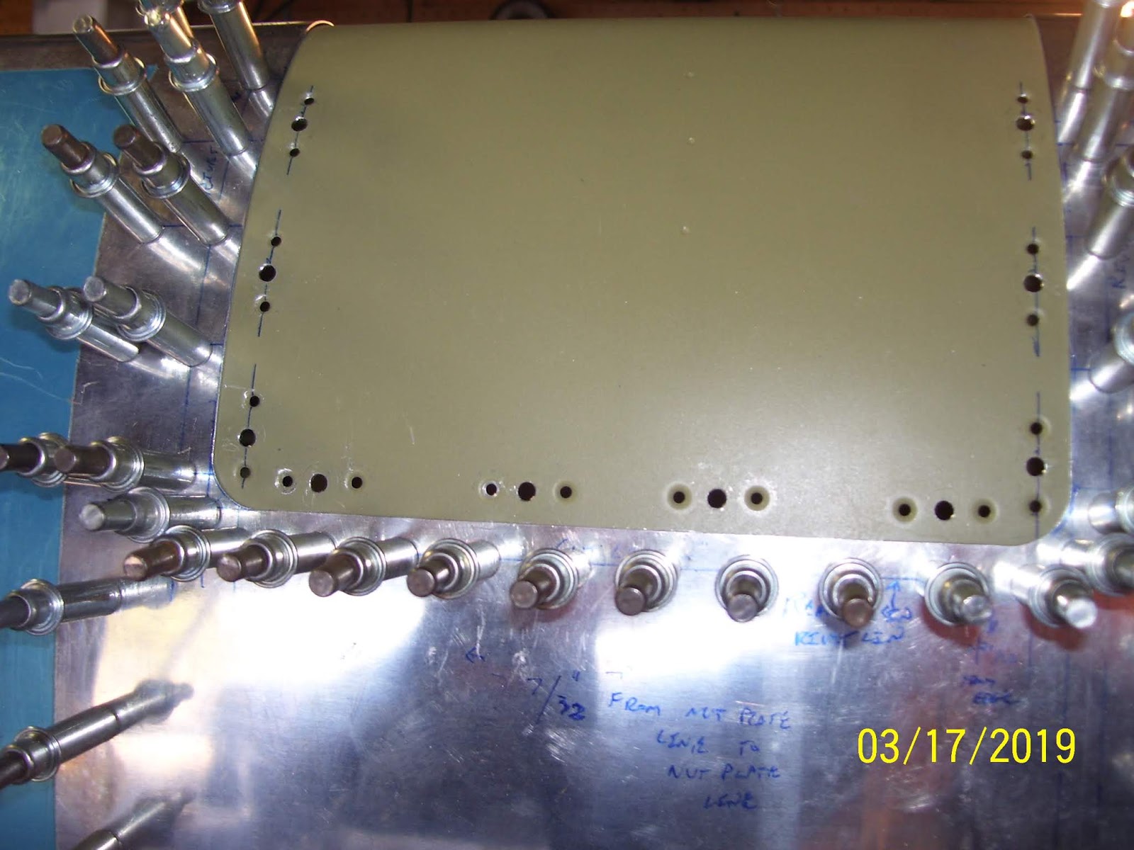
Here are pics of the top and bottom sides after the holes had been upsized and the removable section was removed. the #40 holes for the rivets that will hold each nut plate were already drilled and dimpled long ago, so this exercise is just for the 20 (10 top and 10 bottom) center screw holes.

And here are the top and bottom side pics of the removeable section after I dimpled all the holes on both sides

I was glad that all the dimples seem to have come out well. While setting the dimples in the removeable section was relatively easy since it is not bent very much, forming the #8 dimples on the subskin turned out to be yet another interesting exercise to set these dimples. It required using both hands and my head to position each hole over the male dimple die in my C Frame and keep the metal away from the ram, so that I could use the ball peen hammer to set each dimple by whacking it a few times. Just as when I previously set the dimples for the tank attach nutplates on the subskin several months ago, the holes nearest the front of the subskin closest to the bend were the hardest to set.
 
With the dimples on the removeable section done the next step was to remove the LE from the wing spar for what I hope is the absolute FINAL time before I permanently affix it to the wing spar, and remove the subskin so that I could set those dimples as described above. This also went reasonably well, despite the awkward contortions of my hands and head required to set them.
 

I also took a pic of the new "final" flat template, and the label I wrote on it to ensure that I would be able to tell months from now that I would be able to to tell which template is the "good" one as I proceed to create the same thing for the right wing LE. However since I doubt that I will end up with everything sized exactly the same on the right wing, I think I will end up making a customer one for the right wing as well, when the time comes.


With all the #8 dimples done, it was time to cleco the K1100-8 nut plates in place on the subskin s I could start riveting those in place. I did not quite get to that today, so that will be my next task that I will hopefully complete next week. Here is the subskin with all the nut plates clecoed into position:

I cant believe that I am finally at a point where I can start to assemble the left wing LE for the final time once these nut plates have been riveted. That's all for tonight. Hopefully much more progress next week.

Tuesday, February 5, 2019

Round 2 - Duplicating Pilot Holes for Mounting Screws, Continued...

Continuing from the previous post - Another shot showing the Gorilla tape placement as I continued to locate and drill each hole on the bottom side of the LE:
And here is what it looked like after repositioned the tool and prepared to drill another hole. After the tool was repositioned I would re-cleco each new hole to ensure that everything was as tight and aligned as it could be. Then I would remove the clecoes, remove the tool, reposition, and do it all over again. The rear-most holes were the "easy" ones to do. The holes along the side were a bit of a different story.
After all 4 rear holes were drilled, I then had to start working on the holes along each side. This required removing more clecoes and applying my gorilla tape clamps in different places along the edges, while the clecoes would hold the rear edges down. This became a real exercise in figuring what had to be removed and what had to be secured in order to address each new hole. The holes along each edge were much stiffer and more difficult to lift the metal up in order to slide the tool underneath. This next pic is a bit blurry, but it shows how I setup for the first hole along one edge:
And the result:
I tried to keep both edges aligned by drilling opposing holes along each edge to avoid the metal getting tilted out of alignment over to one side. So here is the opposite hole being drilled:
After all the bottom side holes were match drilled things became difficult. I now needed to drill the same screw holes on the top side of the LE, but my approach this time would be to remove the part and trace around it onto my sheet of .025 aluminum so that I could produce a flat, unbent template for future use. My initial plans will require at least 3 separate parts - one with a clean leading edge, one of one light gun port, and one with the two desired light gun ports. This will allow me to do integral flight testing on different configurations, starting with the clean wing and gradually moving up to the "fun" wing if all prior testing proves successful. That means I will need a minimum of 6 of these parts - 3 for each wing. So I need to be able to make a valid flat template that will yield a properly sized part with #30 pilot holes located in the precise places on both the top and bottom sides of the part to match the screw holes in the subskin.

SO I decided to at least get the bottom holes located and the dimension of the template drawn and measured while the metal was still flat, before I bent it over the LE and over the top side to drill the remaining mounting holes. Here is the new part with all bottom holes match drilled, after I removed it from the LE:
And here is the shot of fitting it to the metal to trace out another one just like it. I aligned it using two factory edges of my aluminum sheet again, just like the first one, to ensure that at least two of the edges were perfectly square to each other.
Now for the really hard part. TO recap a bit from my previous work, the very first time I did this I used a file folder template and attempted to locate all the screw holes in that by using a free-hand drill bit and inserting it from the inside of the LE through the holes in the subskin. This method was less than accurate and therefore was also less than successful, since it left gaps along the edges of the part as a result of the less-than-perfectly-located holes that resulted from this former method. I secured this assembly to the table and match drilled all the bottom side holes to the new template.
After that was done I re-clecoed the part to the bottom side of the LE subskin, and then the fun began.

With no holes drilled or located in the top side of the part yet, my only means of securing the top side of the part to the subskin was to use more gorilla tape and my own hand pressure to keep it flush with the subskin while I used the strap duplicate to locate and drill all the remaining holes. There was no other effective way that I could think of at the time to secure the metal. It acts like a spring as you force it to match the contour of the LE. I could not put it in the cradle because I needed the LE possess the same "mounted" shape on the wing to ensure that the part has the proper fit. So this was indeed a challenge that require the brute strength of my hands and as much duct tape as needed to help keep it flush to the subskin.

Another problem is that I had intentionally oversized the long edges of the new part so that I could be certain that I would not have the same gap issues that I had before. The problem with this is that even though the edges on the bottom side were perfectly fitted and the holes were perfectly drilled, the top side skin was not the correct size or shape yet, so I had to go through another round of free-hand bending and aligning the part to the LE, removing it, applying the scotch brite wheel to remove small amounts of material, and then re-fitting it to the LE again. I bet I did this about a dozen times until I was satisfied that the top edges were ALL fitting properly. Then, and only then, was it time to drill the top side holes.

Here is a shot of top side after getting the rear-most holes drilled out with the tool and I started on the edges. I started on the rear most holes and worked my way toward the front, just like I did on the bottom side. The problem with this is that the bottom side had to remain clecoed in place all the time, so the entire part was locked down tight on the subskin, making it impossible to reposition and insert the tool in the forward-most holes. So to address this problem - guess what? - I had to remove clecoes from the bottom side as well as the tape and clecoes on the top side to reposition the tool for each new hole, so this part of the process took way longer than the bottom side did.
Actually now that I look at my pics I guess what I did was drilled all the rear-most top holes first, and then I started with the most forward holes on both edges. This is not optimal because it can cause bulging of the metal if any slack develops in the part. Unfortunately I did not have much choice in the matter because I need to make certain that the metal around the curve was in the proper position and conforming to the subskin properly in that area, so that is why I did it that way. In the end it turned out OK I think. 


The curvature of this part was actually a bit more matched up with the existing LE, but still not quite. I have some more edge trimming to do on each long edge to ensure that it is fitting correctly, but I consider this effort to be a success. This was definitely much more difficult than I ever imagined it would be. And to think I need to make 6 of these things! 

The last thing to note in this post is some feedback that I promised about the tool. It only cost me 16.00 from Cleaveland Tools, but while I was using it to drill the holes in the top of the part, I found out why it is not very expensive. The guide hole knob on the top that the drill bit fits into is only press-fitted to a hole in the handle. It is not welded or glued - only press fitted. For "normal operations I guess it would work just fine, but for my needs it fell just short of working 100% properly for me.

At one point, basically on my very last hole on the top side, I think the drill bit had some excess slag from previously drilled holes that got hung up in there, and the guide knob popped out of the press fitted hole in the handle. This did cause that very last hole to be misaligned slightly, but it was not bad enough to force me to have to make year another new part. I was able to remove the tool and used a hammer to "fit" the knob back into the hole, but after it came out the first time, it wants to come out much easier now, and so that kind of pissed me off a bit. I'll probably have to order another one to do the holes on the right wing when the time comes for that.

However, there is still one last chapter to this whole exercise, and I will cover that in the next post. it has to do with finishing the flat template after I finally got the top-side holes drilled in this one. 

Wednesday, January 30, 2019

Round 2 - Making a new removeable section and Fitting it to the LE

Weather and holidays kept me from getting much done on the plane. Finally got some warmer weather and started to work on another removeable section to see if I could get it to fit better. To recap a bit, I had use a file folder template and a very inaccurate and un-scientific approach to use a drill bit to pre-mark the #30 hole locations from the subskin, so that I could then transfer those holes from the template to the metal. So basically this approach was designed to create a template with pre-marked hole locations that SHOULD line up correctly with the cutout section of the LE.

Unfortunately after bending the part around the LE and securing it with clecoes, there were some gaps along the bottom section that I was just not too satisfied with, and I also mis-marked one of the hole locations. So I knew I was going to need to make another one and try again.

Here is pick of the old paper template the first attempt at making the removeable section after removing it from the LE. The amount of spring back on the metal was really amazing to see. The part barely has any kind of permanent bend in it after I wrapped it around the top an bottom of the LE. nd left it clecoed that way for several days.
The first thing I decided to do was to use the existing paper template and part to draw out dimensions on my .025 metal sheet and make the edges slightly larger than before to ensure that all the gaps would be taken care of. I drew another border, using one of the factory edges of the metal to ensure that one side was truly straight. The other 3 edges were not from the factory cut, and so I had to ensure that these 3 sides would confirm to the cutout section and would not leave unwanted gaps. I think I added about 1/16th of an inch more material than previously, and I knew that this would most likely mean that I would need to spend a lot more time trimming the edges down to their final sizes to get everything to fit.

Here is the second piece of metal without any holes added:
I felt that the reason for the gaps was because the drilled holes were just off the mark enough to cause the edges to separate from the LE skins a little too much - so how to solve that problem?

I decided that for this second attempt I did not want to predrill the holes using the same paper template approach as last time, and instead I id some research, and ended up ordering anew tool that I had never used before - a #30 strap duplicator show below:
This is a rather interesting tool to say the least, and I ended up having some really good and some not so god experiences with it. The purpose of this tool to provide a way for you locate a hole of an overlapping or top side piece of metal (my fabricated part) that sits on top of another piece of metal underneath (my subskin #30 screw hole) that already has a hole in it that you are trying to match with the part on top. The bent end on the right is tapered to allows you to insert it between two pieces of metal to pry up the top piece if necessary, just enough to allow you to then insert the #30 pin on the other side into the hole in the bottom piece of metal. The top part of the tool then rests on the top piece of metal. The top flange has hardened steel knob on it with a #30 hole. The top part of the bottom flange of the tool, directly above the pin, is also hardened, and has a small recess where your drill bit ends up after you drill the matching hole through the top skin. IOW, the drill bit goes through the hole in the knob on the top, and drill the hole in the top skin, but is not allowed to continue drilling all the way through the bottom skin. This ensures that the hole that is already drilled on the bottom skin is left untouched by the drill bit. The end result is that you are able to drill a hole in a top skin that perfectly lines up with a hole in a bottom skin without ever being able to see the hole on the covered up bottom skin.

Before I could use this tool to drill the matching screw holes, I needed to work on the short edges of the metal that rest on the rear edges of the top and bottom part of the cutout in the LE. I started with the bottom rear edge first, and made sure that the factory edge on one of the long sides was truly straight and butted up against the LE skin.  I would trial fit the straight edge to the bottom side of the LE cutout, remove the part, use my scotch brite wheel to remove some material, and then repeat the process. All I kept thinking at this point was how much I truly appreciate the precision of tools like laser cutters and CNC computer driven cutting and punching machines. Unfortunately I did not have any of that, so this part fabrication exercise was going to be truly freehand.

Amazingly I was able to get  a pretty patch of both radiused corners and the three sides along the bottom half of the LE cutout. Once I knew that the edges were fitting the way that I wanted them to, the next step was to start locating and drilling the screw holes by using the strap duplicator tool. the one MAJOR problem was - with no holes already drilled in the part, how was I going to secure it to allow me to use the tool and the drill to drill the necessary holes. 

The answer: GORILLA TAPE!!!

I decided to use DUCT tape to position and hold the metal in place  so that I could then start using the strap duplicator tool and hold it in position with my left hand while holding the drill in my right hand. I have to say that this process worked out very well, but it was rather involved process that I had to kind of figure out as I went. The first challenge was how to drill the first hole. Critical to that process was deciding exactly where to place the duct tape so that it left enough flexibility to allow me to slip the tool into position and then be able to re-secure everything in pace to make sure that the hole was drilled in precisely the right spot. Here is a shot of the part taped about half way up the bottom of the LE, with the pin of the tool already inserted into the hole in the bottom skin, and the top of the tool in position over the top skin - ready to drill the first hole.


This was most nervous moment for me, because I knew that only the duct tape was the ONLY thing keeping the top skin of the part from moving. The tool does not secure the top skin at all, until you apply pressure on it like you would a pair of tweezers, which is basically what this tool is, which then helps hold the top skin in position while you drill the hole. One thing I realized very quickly, even with everything locked down as much as possible, is that the thickness f the tool itself is going to force the top sin to bend upward slightly, away from the bottom skin. I was concerned that this might cause the top hole to become slightly misaligned with the bottom hole. However, after I drilled the first hole I was very pleasantly surprised to see the top and bottom holes seem to line up almost perfectly. Here is the pin inserted into the bottom skin under the top skin shown above, which effectively locates the position where the hole in the top skin needs to be:
And here is the drill bit inserted into the pilot on the top part of the tool. It only took a second or two to drill the hole in the top skin. As I said earlier, the drill bit hits the top part of the bottom flange of the tool and does not penetrate the bottom hole at all. SO my first experience using the tool was quite pleasant.
This next pic is a little bright, but it shows the freshly hole in the top skin aligning perfectly with the hole in the bottom skin. Mission accomplished.. One down, 19 more to go. I purposely decided to drill the bottom rear edge holes first, because I needed these in pace to serve as anchors to hold the bottom edge in place while I continued to drill the other holes along both edges.

After this first hole was drilled,  developed a process where I would insert a cleco in the new hole, and then repositioned the tool for the next hole. IN this case I decided to drill the other corner hole instead of moving in a line from left to right. This way I could secure both corners to prevent the part from slipping out of position as the skin was raised to insert the tool into the next hole. This kept the side edges and the rear edge of the part in place exactly where I wanted it as I drilled each new hole along that edge.
Here is the second new hole on the other side of the rear edge of the part:

And continuing on, here the two corner holes are now clecoed, and I am finishing up the two remaining holes along that edge. This was done very quickly and worked great. Yo can also see that the edges of the part are almost perfectly aligned with the edges of the LE skin:
I did have to keep removing other surrounding clecoes to make room for the long handle of the tool. It was just another very common repetitive exercise in airplane building of clecoe removal, tool insertion, clecoe replacement, drill the hole, wash, rinse, and repeat. I'll finish the rest of this up tomorrow, as the side edge holes a presented a bit more of challenge and required some slightly different procedures to complete them all. Then there were some problems with the tool that I will discuss as well.


Sunday, December 16, 2018

Eureka!!! Well, Almost.........

This morning I cut the .025 removeable section from the sheet, final formed the edges and corners using the scotch brite wheel, and clecoed the new part to the subskin, and the whole thing ALMOST magically fell into place. In fact I was amazed at how well it turned out. Unfortunately, after clecoing all the holes, there are some small gaps along the rear-most edges and on one side of the bottom portion, and I must have messed up the location of one of the holes, because it was the only one that was substantially mis-aligned with the hole in the subskin after all the other holes were clecoed in place. One out of 20, using much less-than-precise measuring techniques - not too bad.

Anyway, it all started with the cutoff wheel on the Dremel tool again, with the sheet clamped to the table. I tried to leave about 1/16th of an inch on the two sides that I cut to allow for final trimming of a custom fit. This was going fine because I was able to keep both hands on the tool while cutting, and I made the cuts from right to left to keep the wheel from binding up and jumping out of the cut, until I got to the very end of the second cut. I had forgotten that by that time the part's own weight was going to force it to bend just before I finished the cut, and when that started to happen I had to reach and hold the part with my left hand, and this caused the wheel to chew on a small part of he edge a bit more than I had wanted. SO I was not happy with that, but I had already reasoned that I may be making two or three more of these until I was completely satisfied with the fit. SO I did not get too terribly bent out of shape about it.

Here is the sheet after completing the first cut on the longer edge:
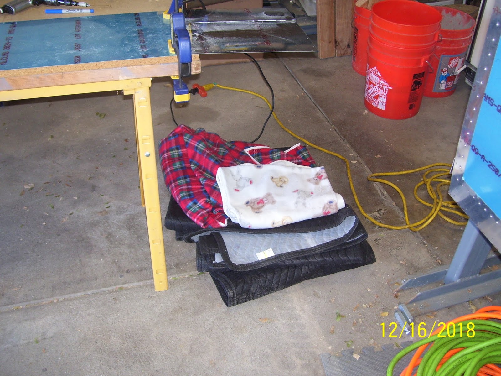
My original plan for preserving the integrity of the part and keeping it from being damaged after it fell away from the rest of the sheet was to allow it to come to a soft landing on some blankets that I strategically placed under the part on the floor as shown below:
And here is the corner of the edge that got mucked up a bit after I tried to catch it with one hand as it began to bend away from the sheet when I got about an inch away from the corner with the cutoff wheel.
After I separated the part from the sheet, next stop was over to the scotch brite wheel for many edge-smoothing and trimming sessions. Here is  shot of the part immediately after removing it from the sheet with the cutoff wheel. Its not real hard to see where the nice clean factory-cut edges are and where I rough-cut them with the cutoff wheel.

I was so glad I was able to use that tool instead of resorting to files and sandpaper like I had to do on the LE skin, which is way to big and cumbersome to be able to use the wheel. After the initial corner forming and edge smoothing and straightening, next came the long painful process of trial fitting the part with the LE. Fr some unknown reason I decided to start with the top side, not quite knowing what I was going to do once I got to the point where it wraps around the front and on the bottom side. I was pleasantly shocked to see that most of the rear edge clecoes and the sides were aligned quite nicely. the left edge was laying down very nicely next to the edge of the LE skin on that side, and the rough cut edge was overlapping the other side, but not by much. 
Next is a series of pics after I got the corners shaped enough to allow them to sit flush on both sides. There are some gaps, but as I mentioned before, this may be OK to allow for layers of primer, paint and sealer when that day comes. All I was interested in right now was the general overall fit f the part so that it would lay flush on the surface of the subskin, and as close to the edges as possible, with all screw holes clecoed in place and aligned. If I could achieve that on attempt one I would be very happy. 


With the top side fitted, I removed the part from the top and moved it to the bottom, where I repeated the same fitting, scotch brite, refitting, cleoeing exercise that I performed on the top side:
On the bottom right rear corner you can see the one single hole that is not clecoed. That turned out to be the ONLY hole that was not properly aligned with the hole in the subskin. Unfortunately there is nothing I can do to fix that problem other than mark and drill a new hole in a new part, meaning that this one is "toast" because of that issue alone, let alone any of the other edge gap issues that also exist. Unfortunately the misalignment is so bad that I cannot just fix it when I up-drill the #30 hole to the #19 hole, so that means I whole new part has to be fabricated. Here is a blurry close up of that hole where you can just see how badly misaligned it is.

And here you can see the gapping on the left side of the bottom edge. The pic makes it looks much worse than it really is, but it is quite noticeable, compared to how the other edges are lining up with the LE skin. 
And here are a couple more showing the gap along the bottom and right side edges of the bottom portion of the part:

At some point I decided that instead of marking up a second part I was going to go ahead and check the fit of everything AFTER wrapping the skin from bottom to top and securing it on both sides to see how well that worked out. ONce the edges on either side, the corners, and the rear-most edges were proven to allow the part to rest correctly against the subskin on both sides without any overlapping or interference with the LE skin, I started out with everything clecoed in place on the bottom, and then just used my hands to easily bend the aluminum around the front and over the top side. TO my amazement everything laid down on the subskin as expected. I clecoed the holes in progression from the bottom side up, and then the top side down, secring the edges as each hole lined up with the hole in the subskin. It fit like a glove.


So it was looking good until I checked the following area. Just as I had mentioned before when I noticed the LE skin does not quite sit completely flush with the subskin in the very front, right where it curves. The inboard side of the LE fits a little better than the outboard side. Well, true to form, the part, just like the file folder template, laid down very nicely on the top of the subskin, but there is a complete mismatch where the LE skin curves around, and the new part was very noticeably mis-aligned with the curvature of the LE skin.


As I also previously stated, my plan to address this in the easiest manner is to build the removeable part up with fiberglass or carbon fiber so that it matches the contour of curvature on either side of the LE. SO that will take a little bit of some unplanned work to take care of that little issue. It is better to fic this problem that way, so that the part lies flush against the subskin, than to try to adjust screw hole locations or skin size to get the right "bend" in everything. So, the MOST important thing about this is that one way or the other, the removeable section WILL properly align with the contour of the rest of the LE when it is all finished up. There was already plenty of other fiberglass work to do when I add the lighted gun ports to the front of this part, and so now that it looks like I will also need to do some composite work on the "normal" part with no gun ports, I guess that will just be more practice opportunities for me to get it right before I mess with the "funner" stuff.

The last pic I took today is just to show that from a distance, except for all the new clecoes in all the new holes for everything, it looks just like it used to look before all the measuring and cutting took place. When all those hole are riveted in place it will even more like the regular old un-modified LE that it used to be. So, just as with everything else on this project, I feel 90% done with all this, with 90% more left to go. But at least most o the hard work is done, until I get around to doing it all over again for the right wing.


All for now. KPR