Friday, January 6, 2012

423 hours - Pounding rivets on the left elevator (Finally!)

I honestly started wondering if I was ever going to see this day arrive or not. Last night I brought my tubes of blue RTV sealant inside the house to keep them warm so they would flow easier into the syringe that I use to apply it to the trailing edges where the stiffeners come together. I unclecoed everything, applied the sealant to the elevator at the designated points, and then attached the E713 counterbalance skin by quickly setting the 4 rivets with the squeezer that cannot be reached once the frame is clecoed into place.

I little trick I found for "helping" the tip rib slide into place is to take an allan wrench and stick the short end into the forming hole on the aft side of the rib, rotate it 90 degress so that the short end is sitting against the inside of the rib web, with the long end sticking out. Now you have sort of a handle to grasp to pull the rib into its final position. It needs a little help to slide up and over the dimples due to the angle that it is inserted because of the pre-attached E713 counter balance skin.

SO here is the bottom side almost completely riveted:
I will finish up the top side tomorrow:


Here are the shop heads of the forward spar rivets (bottom side)

 and a shot of the bottom side rivets for the tip rib:


We'll see how far I get with the trim tab over the weekend. Sure feels good to be pounding quality rivets again. Wouldn't it be nice if I could finish it by being able to activate my installed trim tab servo and watch the trim tab move up and down on its own. We'll see.....

Wednesday, January 4, 2012

420 hours - Prepped the left elevator for assembly

So yesterday I needed to back rivet a few less than desireable rivets that attach the elevator skin to the Trim Servo support bracket. The shop heads were just a bit uneven so I smashed them down a bit more. I also needed to debur the edges of the skin which I had not done yet.

Tonight I finished deburring the edges of the skin, and then I needed to touch up a few areas on the spar and on the trim support bracket where the loose elevator skin had managed to scrape away some material and primer from the trim support bracket. As much as I tried to prevent this from happening, I failed. The cutout for the trim tab forces you to deal with a rather unwieldy piece of aluminum that wobbles around quite a bit. The corner of the upper skin would ocassionally get lodged behind one of the attach rivets for the support bracket, or the top side H5 stiffener woudl scrape against the support bracket. I lightly sanded all the spots and sprayed a light coat of primer on them after masking up the skin just a bit to prevent overspray from getting on the exterior skin.

After the primer was dry I went ahead and clecoed all the elevator parts to the skin as a kind of precursor to the actual event when I will cleco and rivet everything together for real - probably tomorrow. I did this for several reasons:

1. It was very cold on the garage tonight and I did not want to work with cold RTV which has to be squeezed into the small areas between the trailing edge stiffeners similar to what was done with the rudder and the right elevator. This has to be done before I can close up the the skin for the last time to prevent cracking due to vibration in that area.

2. Remember that in order to prep the replacement tip ribs and spar, I had to attempt to drill and dimple the holes in the new parts with a skin that had already been match drilled and dimpled for the old parts. I had not had any of the new frame parts installed back on the skin since I had dimpled and primed everything, so I wanted to make sure that the dimples still kept everything in alignment. The tip ribs were a little bit off from the skin but they were able to be coaxed into position by inserting the clecoes along the way. Everything looks like it will fit as expected, so no nasty surprises there.

3. I still need to cleanout all the remnant primer shavings that fell off the vinyl covering that I finally removed last night from the inside of the skin. It tends to flake off the vinyl as you peel it off the aluminum, and the it contains an electrical charge that attracts all the primer shavings to the skin, so it tends to stick to everything it touches, and is somewhat difficult to remove. I'll blow this out with my air gun tomorrow just before I apply the RTV and cleco it all back together for the last time.

ONe last thing I discovered is that my clecoes do not seem to be holding the top rear spar in place very well. It seems that the countersunk holes in the top of the spar are enlargened enough so that the clecoes just do not hold it into position. this will be sandwiched by the other trim tab hinge after I get the elevator riveted together, so I am not worried about anything here. The bottom flange of the reat spar was dimpled so it holds together with the skin just fine.

SO here are a couple of pics of the underside of the left elevator clecoed together for a trial fit tonight:


I also trimmed away a little of the forward edge of the skin where it sits right next to the counterbalance skin on the outboard tip of the elevator. This skin will get rolled to close up the leading edge after all else has been completed. I noted early on that the edge of this skin that sits next to the counterbalanvce skin was actually rubbing it just a bit, whereas the same area on the right elevator had a sufficient enough gap between the two parts so that it was not a factor. So I just sanded down that edge a bit to provide enought clearance to roll it without it binding on the edge of the counter balance skin. It's all the little details that matter in the end, so as much as I really want to close it all up and smash rivets on this final empennage part, now is the time to step back, take your time, and think about all the things that you have missed along the way, or that you put off until the very last moment.

I hope to at least start riveting it all together tomorrow night. Then I can focus on final assembly of the trim tab. Almost there......

Monday, January 2, 2012

416 hours on the hobbs - happy new year brings a completed elev frame!

Happy new year to all who venture on to my site! Wow - what an eventful past few days around here. I had prepped the parts and was ready to prime on 12-30-11, but that day the winds were howling at 50 plus mph throughout the entire state of Colorado - not a good day to try to prime anything in the windy garage, so I waited. Then I had to partake in all the holiday festivities on New years eve, so we went downtown to watch the people get drunk and check out the fireworks. Got some really cool flashing light 2012 eye glasses too.

New years day was a treat. Got the parts primed in the morning, and then went flying with Kevin in the afternoon. What a wonderful flight - smooth as silk and hardly any wind, and a beautiful sunset to round out the day. A great way to ring in the new year.

Fast forward to today - FINALLY got a good solid airplane-building day in the books. Started where I left off over a week ago when the first rivet attempt of the tip rib met with disaster. I am happy to report that todays activities had much better results.

With a lot of careful planning and thinking things through, I changed my approach to dealing with several of the rivets of the left elevator frame this time. The first step was deciding to use gravity as friend when working with the hand squeezer to attempt to set the An470 rivets on the flanges of the two tip ribs to the main spar.

It starts with setting the frame parts on the bench with the E704 counterweight rib clecoed to the spar. (Get ready for  aton of pics and another very long post!


Click on the pic to enlargen it to show more detail. I have a small thin piece of 3/4 inch plywood about 2 feet long that just fits inside the web of the spar in between both flanges. I aso have two other smaller pieces of 1x2 that will fit in certain areas. I used these pieces of wood extensively for this and many other building/clamping scenarios. The 3/4 inch wood is just thick enough to allow the flanges to sit above the table to you can clamp the crap out of everything  and not damage the parts. I recommend sandwiching the parts between 2 pieces of  wood as much as possible. I then clamped everything to the drill board, with the end of the spar hanging over the edge just far enough to clear the clecos, rivets, and hand squeezer/rivet sets. The E704 is facing up as shown, and is clecoed from underneath and the sides.

I used a 1/2 inch long x 3/8 inch wide flat set on the bottom, and the 1/8 inch x 3/8 inch round headed rivet set on the top of my flange yoke. Oh yeah, I had also managed to grind down the glange yoke a bit more, but after todays exercise I find that I need to do it even more. Ya gotta make custom tools from time to time.

I put masking tape inside the round headed rivet set to help prevent smilies - works fantastic. Apply the tape to the top of the set, mush down the middle using the head of an AN470 rivet, then secure the tape over the sides of the set, and take an Xacto knife and trim the excess tape off. be careful not to cut yourself.

Next is looking down from the top of the E704 rib. ONe cleco holds one side of the flange, another cleco holds other far side attach point, and the rivet is placed on the rib side of the assembly to froce the rib flange tight against the web of the spar. The principal of this apprach is quite simple: allow gravity to force the rivet set on top of the rivet head, hold the parts together, and make it easier to set the rivets using the hand squeezer.

Here is a shot with the rivet shank extending out the bottom


Next is a pic of the hand squeezer in position. there is a trick to fitting it inside the flange when using the longer 1/2 inch rivet set. You ahve to leave enough room to allow the sets to slide over the outside of the spar flanges to get it into position. Then, if you need to, you can screw or unscrew the adjustable set holder to get the correct distance between the two sets to smash the rivet. If in doubt, start with the rivets sets slightly too far apart - just enough to thicken up the rivet shank to allow you to get an idea of how much further you need to adjust the set holder to get the proper shop head on the rivet. This is known as "dialing in" the rivet sets to the correct depth.


You have to get the thich part of the yoke to sit on top of the spar flange in order to allow the AN470 rivet set to position itself over the dome-headed rivet properly. The magic of this arrangement/method is that gravity is now holding the parts together and the rivet set on top of the rivet, so you don't have to work as hard to keep everything in alignment. No matter what anyone says, both the hand squeezer and the pneumatic ssqueezer are very heavy and awkward tools to work with. Anything you can do to make it easier to work with either of these tools is a huge plus. The other magical thing about this is that it makes it much easier to align the rivet set on the bottom to ensure that you are setting a perfectly straight rivet.

Here is a shot of the rivet after it was set:


This next one is a little blurry, but it shows more detail about how the sets are aligned on the rivet once the squeezer is placed into the correct position. You can check to ensure that the dome-headed rivet set is properly positioned over the rivet head by looking at it through the opening in the corner of the rib and the spar. Then you can check to ensure that the bottom flush set is centered on the rivet shank so that you won't risk clenching the rivet over to one side or the other, and will drive it straight down the center line.


WHEW! Previous problems all successfully averted. Both rivets for the flange of the E704 rib are set successfully.


Now on to the E703 tip rib. Although not seen in this pic, I ahve another piece of wood underneath the tip rib, and then the one top, and the clamp is sandwiching the web of the rib in between the two pieces of wood. This allows me to clamp it tightly to the bench. I had to leave some of the clecoes that join the webs of the two ribs off in oder to fit the wood in place, but the clamping helps to keep the parts together as they are supposed to be. The two copper clecoes on the far right side of the the next pic are the ones that are holding the flange of the E702 spar to the back side of the tip rib. This is the next area to be riveted. The E702 spar is now sticking straight up. I did not need to support it with anything, but a helper here is advisable to keep it from flexing too much.


Next is a really bad pic - trying to show the flanges and how they are sitting against the rib. Still not exactly flush but definitely flush at the point where the rivets are being applied, so all is good here. Also notice how the bottom if the rib flange is sitting just above the top of my drill board. Make sure you are not crushing the flanges of anything when you clamp the parts to your bench.


Here is the flange after both rivets have been set. Still not the best, but it is acceptable.

With both end rib flanges successfully set, time to attach the webs of both ribs together. This was a very interesting adventure, adn I ended up doing it almost completey differently from the way i did the right elevator. Here is the setup on the end of my work table:

Now to elaborate on this a bit. When you get to this part, you basically have to be able to get a squeezer to fit in between the 2 flanges from both ribs. This equates to a little more than an inch or so. This is why I decided to buck these "rib-joining" rivets on the right elevator instead of squeezing them, because I could not bring myself to accept what I was going to have to do in order to try to get the flange yoke to fit inside this assembly. After thinking it through a bit more, I decided to give it a try with the squeezer. I changed sets by removing the 1/2 inch long flat set and replacing it with the 1/8 inch x 3/8 inch flat set. This was necessary to allow enough room to insert the yoke between the two flanges of each rib.

The trick is that you cannot set the adjustable set holder on the squeezer to the proper depth, because you are not able to fit the rivet sets over the flanges of both ribs. Instead, you ahve to start by screwing down the set holder far enough to allow you slide the rivet sets over both flanges - long side first, followed by the short side. Then you ahve to position the sets over the rivet adn adjust the set holder back out (unscrew it) to get it to the proper depth. the last pic above shows the squeezer handles resting on the back of one of my card table chairs, which just happens to sit almost flush the clamped assembly on my work table. I used the chair back to support the the squeezer handles after I had adusted the sets to the proper depth. Zyou cannot remove the yoke until you reverse the procedure described above to widen the sets far enough out again to remove the squeezer. The chair method between rivets worked out great.

Next is the Squeezer in action as I set each of the rib rivets.

So no I did not use the gravity method for these. the main reason is that this area is open enough so I can clearly see if the rivets are being set correctly on both sides while I squeeze them. I will also take this opportunity to report that setting AN470 structural rivets with a hand squeezer is very hard work. I chose not to try ANY of this with the pneumatic squeezer because it is just too heavy and bulky.
Done with these rivets:

Next were the support plates and K1000 nut plates to the back side of the spar. I did these slightly out of step as I wanted to ensure that the tip ribs went on OK before thinking about doing anything else.

I basically used the rivet gun and my thin man tungsten bucking bar to set thise rivets. I set all the top or mid-level rivets, then turned the spar over, reclamped it, and set the last six rivets shown clecoed above. I seem to ahve found that using the smaller bucking bar works better for me when I set the rivets for support plates. The rivet callout turned out to be a bit long, and squeezing these rivets here usually ends up with clenched rivets that must be drilled out adn redone. If I buck them I find I ahve no problem setting slightly longer rivets.

Small end of the spar:

...and the larger end at the root:

Next I used the no hole yoke to set the 4 flush rivets at the root that attach the forward flange of the root rib E705 to the E702 spar. Those came out fine.


12 more structural AN 470 rivets to set to attach the control horn to the frame adn I am all but done for the night.....
And some shots of the back plate rivets all installed....

What a relief to be done with the frame finally! tomorrow I should be able to start attaching the frame to the skin. I also need to set the trim support bracket rivets a bit better as my back riveting did not turn out as good as it should be for those rivets. Also, I have offically maxed out the memory on my 2 GB SD camera disk since I began taking pics of this project in May of 2009. I got another one for Xmas so disk one goes in the file and I start a new chapter of the build on the new disk. Fitting for the beginning of a new year I guess.

Still several steps to go to finishn the tail feathers, but getting ever so closer now.......

Thursday, December 29, 2011

410 hours on the hobbs - Replacement ribs and spar arrived

Finally got my replacement E702, E703, and E704 replacement parts from Vans yesterday. I ended up having to re-do about a half a page of prep steps in order to get everything back to where it was before the riveting blunder described in my previous post. When the parts arrived, they were in a very thick cardboard tube. I removed the spar only to find that the flange on the tip of the spar had been badly bent over during shipping. Upon close inspection, and after bending the flange back into place, it looked like the rivet holes were not compromised, and the skin was not creased in any way, so I was able to flatten everything back out with the rivet gun, a flush set, and a back rivet plate. I was beginning to think that this elevator is becoming a bad omen for some reason, but elected to try to push through it and keep working on it.

I also managed to remove the former E703 tip rib from the former messed up spar. Unfortunately the rivet holes where very badly mangled after attempting to set the rivets with a flange that had become badly deformed after screwing up the E704 counterbalance rib (see previous post). I tried to take my rivet gun with the mushroom flush set and lightly bang out the mangled metal around each hole using a back rivet plate, which seemed to work OK, but the rivet holes still appeared to be a bit oblong from attempting to set the rivet in a badly bent flange. I had originally thought I might be able to re-use the tip rib so that I would have less fabrication to do on new parts, but that turned out not to be the case.

Here is a list of all the things I have done in the past two evenings to get all three parts back to the state where I am ready to attempt riveting again:

1. Flute both ribs and straighten the edges with my edge bending tool. I found another tip on a builder web site after searching VAF that reminded me that the real purpose of fluting these two ribs is to make absolutely certain that the webs of both ribs are flush with each other with no gaps. This makes attaching the E713 counterbalance skin a much easier task, since th holes line up pretty well if the ribs  both fit together properly.
2. Remount the E714 lead counterweight so that I could re-drill the bolt holes in the forward flanges of each rib. With the bolt holes already in the counterbalance skin and the lead counterweight, I was able to take a number 10 drill bit and lightly mark the forward flange of each rib by turning the bit by hand. Then I disassembled the rib assembly and step drilled the holes in each rib flange to the proper size using the same technique described in earlier posts when I originally performed the counterweight preparation steps. These new holes actually turned out much better than the previous holes. It's much easier to mark the flange when the holes in the E713 counterbalance skin and the E714 lead counterweight have already been drilled. The new holes ended up much closer to the center of the flange this time, so that was a good thing.
3. Match drilled the rivet holes in each rib web attaching the E703 and E704 ribs together. Also match drilled the flange rivet holes in both ribs. (You know, the ones that totally screwed up when attempting to rivet them previously).
4. Clecoed the entire elevator frame to the elevator skin and match drilled all the remaining spar-to-skin attach holes, including drilling the 4 holes that are not predrilled on the ends of the E703 tip rib. Match drilled the counterbalance skin holes to the holes in both ribs.
5. Disassembled everything, deburred all the holes in the ribs and the spar, and dimpled them.
6. Countersunk the 4 holes on the inboard section of the spar that attach the E705 root rib to the back of the spar.

Now I just need to finish edge deburring the parts, and clean, prep, and prime them, and I will be back where I was a week ago, supposedly ready to rivet. I will tell you that it was not fun trying to cleco and match drill the new frame parts to a skin adn other parts that had already been dimpled. I am a little concerned that the holes and dimples may not line up as well as they did before, but I have done this sort of thing in the past and not had any problems with the parts fitting together correctly, so we shall see....

I went on VAF in search of info about how others had tackled the end rib riveting problems. Not surprisingly,  I found many others that have had similar problems with this part of the assembly going back as far as 2005. Most were saying that the solution is to hand squeeze these rib flange rivets, and to use the tip of riveting the flange of the E704 rib first, followed by the E703 rib, before attaching the two ribs together via the rivets in the webs of each rib. Van's instructions still say to attach both ribs together first, and then attach the whole assembly and rivet the flanges to the spar, which just does not work out if you try to do it that way. The problem is that while most were describing using the workaround, I could not find any pics of the yoke, rivet sets, and positioning they used to set thse rivets. Then I finally found one. You need to use a flange yoke, a 1/8 inch x 3/8 inch AN 470 round head rivet set, and a 1/2 inch x 3/8 inch flat rivet set on the other end. It is always a little harder to squeeze 1/8 inch rivets with a hand squeezer, but it can be done, and you have much better control with the hand squeezer. You have to leave the tip rib off when you set the flange rivets for the counterbalance rib, because the thickness of the squeezer prevents you from being able to get the round headed set over the head of the rivet due to lack of clearancefrom the tip rib. All you have to do is flex the counterweight rib out of the way just a bit, adn you can set the rivets correctly.

I bet I could convince Vans to give me job where my sole responsibility would be to evaluate and identify all of the latest build issues from their current set of plans for every airplane kit that they provide, determine the work arounds that are being used to correct the problems, and update all of the plans for each aircraft to incorporate the new and better building techniques. The fact that they seem to have no interest in receiving this info and making the changes to their aging sets of plans really pisses me off.

Anyway, I digress. For the record, I wanted to include some "before" pics of the fit of the flanges for both tip ribs against the spar before I rivet them together. If you compare these to the pics at the end of the previous post, you will see just how messed up the flanges of both of the ribs are. The way they appear in these next pics is exactly the way they should look after the flange rivets are set:

Notice that there are NO gaps in between the flanges in the above pics. Everything is nice and flush. Should be ready to try this again tomorrow, after verifying the correct rivet lengths, ensuring the parts are clamped tightly to the table, grinding down my yoke just a bit more, and borrow another set of hands to help hold the rib out of the way. Maybe this time it will work out......MAYBE.

Friday, December 23, 2011

405.5 hours on the hobbs - prep parts for primer and start riveting

Nothing posted for a while. Short story is that I prepped and primed all parts with primer, nad began to rivet the tips to the lef elevator E702 spar. I bucked these rivets just as I had done before on the right elevator, expecting the results to come out the same. What I got instead was severely clenched rivets, followed by less than succesful attempts to remove the rivets, followed by more unsuccessful attempts to drive new rivets, followed by badly deformed holes, and severely deformed aluminum resulting from the attempts to drill out and remove multiple rivets . As a result, the spar is trashed, as it the counterbalance rib, so new parts are on order. Not happy about this at all, since this will seriously challenge the accompishment of my goal to be finished with all the tail pieces by the end of the year.
This will set me back by at least a week if not more.

First is a pic of most of the trim tab and elevator frame parts all cleaned and scuffed and ready for primer.

The only thing that was not prepped was the other half of the trim tab hinge that still has to be fitted and drilled. And of course, now I will have to prepare a second spar, third counterbalance rib, and second tip rib when they arrive from Vans.

Next is the trim tab and elevator riblets, the trim tab control horn halves, and the trim tab-half of the hinge, ready for priming on my makeshift priming table.


Next is all the other parts hung up on the wire and ready for priming. Lots of parts for both the elevator and trim tab.


And now for the really funny part. Normally I have been using my expensive two part self etching primer for the larger pieces of aluminum. The only realt reason for this was to avoid having to buy cases and cases of NAPA 7220 primer in the can. When I went to open the quart can of the primer base, it looked more like the material used to make Silly Putty than primer, and had about the same rubbery consistency. Needless to say that this was not going to go through a spray gun, no matter how much I tried to reduce it. So another $64.00 down the drain. This pic was of the setup for the two part primer application just before I discovered the primer was bad.

So the solution to the problem to avoid any further delays was to go ahead and use the 7220 primer for all the parts. Here they are all ready for riveting:


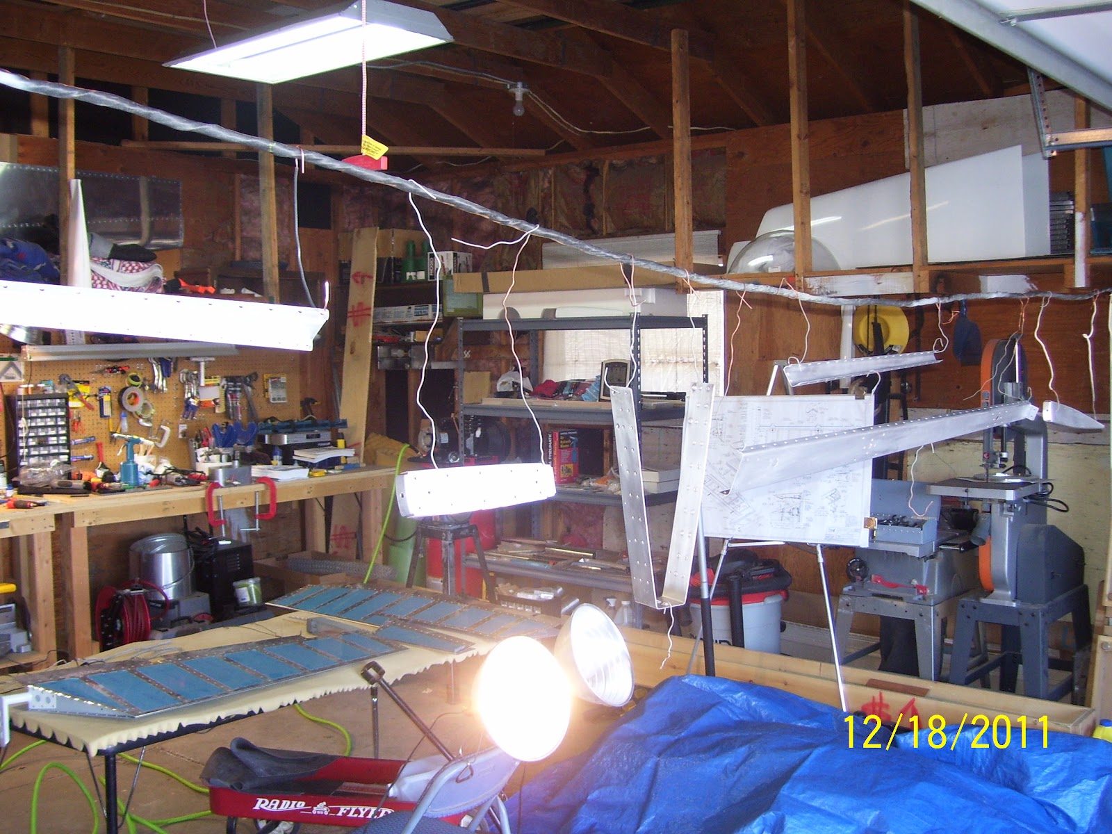
Next is a more close up pic of yeat another attempt to instroduce an adequate amount of light to one side of the parts that are strung up on my priming wire. My garage lights are closest to the work benches, and I string the wire up on the opposite end for ventilation and to prevent priming other things not intended to be primed, but I then suffer a penalty for lack of light on this area. The problem is that I get great sun light from the open garage door, so I can see that side of the parts very well, but I get shadows and severe lack of good light on the other side. So I tool part of the wing jig, mounted two of my High intensity reflector lights to the angle, and that seemed to work OK.


And finally the crappy rivet on the top that has set me back yet again. I can't even begin to tell you how sick and tired I am of trying to buck rivets in all these teeny tiny places. You do everything absolutely correctly to get to this point, and then it all goes to shit in a heart beat. Really sick and tired of this. Oh well, get new parts and try it again.


Followed by the crappy pic of the other side of both rivets. Really really bad.......No chance to salvage this - they had to come out, which lead to the distortion and final demise of the spar web in addition to the rib flange. If your shop heads end up looking like this, then they need to come out - no question.


Another one of the shop heads. Here is where is starts to get strange. It's hard to see in the pick, but if you look at the top rivet head, and then notice the bottom rivet head appearing at a slightly different ange than the one on the top, this is how the rivet shafts were sitting in the metal before I even began riveting them. They were obviously at different angles to each other, implying that something was wrong with the spar web or spar flange, or both. I noted that the manufactured heads on both rivets were not sitting at the same angle either. I ahve no idea why or how this section of the spar would ahve become so messed up, other than this possibly happening at the factory when they were forming the part on the bending break. It would not be the first time I received a badly formed part from the mothership, and probably won't be the last. Of course, it's much easier to blame them than it is to blame me, right?

And here is the setup I used - same as I did for the right side.

For whatever the reason, I decided to go ahead and set the two rivets that attach the tip rib to the E702 spar flange which is 90 degrees opposed to the other flange that attaches the counterbalance rib to the spar. Those were set with the pneumatic squeezer using the flange yoke without any problems. Unfortunately they will have to come out since the spar is now damaged from the failed attempts to drill  out and re-set the rivets for the counterbalance rib. I was so disgusted at this point I just decided to order all the tip ribs and a brand new spar:


And the final pic that shows just how messed up the fit of the two ribs is against the spar. None of the flanges are lying flat against the spar or the ribs. This was totally messed up and I am still at a loss as to the reason why. The counterbalance rib flange was bent while trying to move it out of the way to drive the rivets with the double offset rivet set, so I can explain that one, but the fit of the tip rib flange to the spar is also messed up.That one I cannot explain. Hopefully the next post will be a better one.....

Sunday, December 11, 2011

402.5 hours on the hobbs - fabricated 3 riblets for trim tab and elevator

After a ton of research on Steve Riffe's and several others builder sites and logs, and a break in our super chilly weather here in Denver, I was able to fabricate the two end riblets for the trim tab, as well as the end riblet for the left elevator cutout which sits adjacent to the outboard edge of the trim tab. I also have to say that I did get a little distracted listening to our Denver Broncos pull out another miracle finish against the Chicago Bears this afternoon, to take sole possession of first place in the western division. Go Broncos!

This weekend was slow in terms of airplane building. Had to do the annual Xmas shopping yesterday, and got a new Smart phone as an early present, which I of course I just had to mess around with this morning. So the weekend airplane work did not actually commence untlil about noon today.

As a preface to the coming photos, let me just say this: Did I save any time on my build by choosing to make riblets instead of bending the dreaded tabs - NO! Did I end up with more piece of mind using the riblet solution without ruining any parts, or having to build a second or even a third trim tab in the process -  YES! So, if you are builder who seeks info about bending the tabs, do not waste any time hunting my blog for that. However, if you choose to cut the tabs off and make the riblets, then read on.

During the process of making the riblets, I encountered many twists in the road that most other builders don't seem to comment about, and I have tried to mention them in this post for the benefit of future builders. If you read my blog, you know by now that I like the details, and I also like to dispell as much of the doggone mystery about some of this stuff that I can.

Here is what I learned and how I made my riblets:

I had already trimmed the edges of the trim tab skin very close to their final state, but I needed to trim the edges of the elevator cutout where the trim tab resides just a bit more to allow enough clearance between the trim tab and the elevator. In this pic I have the skin laid out on my table with the 2x4s slid underneath. I then clamped everything down, and performed a bit more "dremel surgery" with the cutoff wheel to carefully trim away about another 1/8 inch of material from the top and bottom outboard trim tab cutout edges of the elevator skin. My measurements for the long edge of the trim tab cutout were about 17 and 22/32 inches, so this is the minimum amount needed to allow the trim tab to just fit inside the cutout in the elevator so that the edges of the trim tab will line up with the edges of the elevator.


This setup provided enough stiffness and separation of the edges of the elevator to allow me to keep two hands on the dremel tool to keep from making a costly mistake. One slip up here and you will order a new skin, so take your time, secure the work, and move slowly with the dremel tool, and it works out fine. I cut just outside the reference line I drew to leave a bit more material than desired, and finish trimming by using a file to trim away the remaining material up to the reference line.

Next is something I am a bit concerned about, and I will need to talk to Vans tomorrow, before removing any more material on the edge. Vans has you draw a line on the elevator that is perpendicular to the long trailing edge to determine the bend/cut line for the tabs. I expected that the corresponding matching edge of the trim tab would also be perpendicular to the LE of the trim  tab so that both edges would line up evenly. Unfortunately, I found this not to be the case. Upon trial fitting the trim tab in the cutout of the elevator, I found the outboard edges were not aligned as expected, and the trim tab edges are anything but perpendicular.

You are supposed to end up with a minimum gap between the elevator edge and the outboard trim tab edge of at least 3/32 inches. To correct the problem,  I think I will be able to trim the extreme trailing edges of either the elevator or the trim tab to even out this line, and still have the appropriate gap. SO much for cutting straight lines on everything. The next pic shows the additional amount I originally marked that needed to be trimmed from the elevator. Advice to future builders is to avoid trimming anything additional from this area until you actually start fitting the trim tab and hinge assembly in place.


And here it is after cutting and filing the excess down to the new line:

Next, the riblet fabrications begins. What do you need?

2 Vans practice Kit ribs (I don't know the part number but there is one for them - call Van's to find out what it is. thanks again to Mike Rettig for providing me some brand new untarnished ones so I would not have to tear apart my completed practice kit like Steve did!

The riblets fabricated from the ends from these two ribs will go in the OUTBOARD edge of the trim tab and in the edge of the elevator that sits next to it.

1 E703 elevator tip rib. Order one from Vans, or use a discarded one if you messed one up during elevator construction.

The riblet fabricated from this rib will go in the INBOARD edge of the trim tab, or the edge closet to the rudder when mounted on the fuselage.

Here is a pic of the remnant from all three ribs to give you some idea of where I made my initial cuts.

Now to describe the process I went through. This was a bit painful, and involved a lot of measurements of the gaps between the skins, and length measurements from leading to trailing edge, followed by transfers of all those measurements onto the rib stock, followed by more measurements, and more trimming, etc. I must have measured everything about 20 times before deciding where to make the first cut to separate the ends of each rib from the original part.

I essentially used a "more is better" approach, meaning that I took my original measurements, and added a bit to them just to be sure I did not cut anything too short. The elevator riblet pretty much gets cut symetrically off the end of the practice kit rib, while the other one for the outboard edge of the trim tab tends to have a bit of an angle on the leading edge due to the angled nature of the trim tab forward spar. The web on that spar, which has a Z bend on both ends for the flanges that attach to the top and botttom of the trim tab skin,  is not vertical, but sits at an angle.

Next I will go ahead and provide some "finished" photos of each riblet. First is the OUTBOARD or smaller end riblet for the trim tab. On the bottom of the forward part of the riblet you see a small cutout for clearance of the trim tab spar flange. You have to make this cutout to clear the edge of the trim tab spar flange. I suggest measuring to obtain about a 1/8 inch clearance, which is a standard clearance for most other non-attached rib-to-spar clearances. The hole that you see is a tooling hole from the original rib - I consider it a lightening hole (haha). Just debur the hole, and that is all you need to do with that.

Also notice the clearance from the end of the riblet to the trailing edge of the trim tab, and a slight rise in the forward flange of the trim tab skin where it joins the top flange of the trim tab spar. I was not very happy about this. It seems that the angle of the prefabricated practice ribs does not quite perfectly match the angle of the trim tab skin after attaching it to the forward spar. I will need to decide how to manage this, but for now some scuffing for primer and trying to work the edge of the flange of the riblet a bit more to reduce the width are all I can think of. The trailing edge of each riblet will sit just a bit forward of the trailing edge of the trim tab and the elevator to achieve the correct angle to fill the gap between the skins. Of all three riblets, this one does the worst job of mating correctly to the trim tab skin. Options are to make a wood form, take some of your spare metal, and form your own, as many other builders do. I'll have to ponder that this week to decide what I will do - leave it as is or form my own.

You should also know that I did not trim anything off of the trailing edge of this riblet - I used the original trailing edge and only trimmed the forward portion to fit it. Lastly, and this is a personal choice - you can face the web of the riblets inward or outward. For the trim tab I chose to face the web of the OUTBOARD riblet toward the outside to create a difinitive edge that will have the same effect as bending the tabs.


Next is the other side of the trim tab, or the INBOARD side. This riblet is made from the E703 Elevator tip rib, and is much longer and a bit wider than the one on the outboard edge.It will be placed as shown with the web facing inward, to match the edge of the E705 root rib, and allow solid rivets to be used on the flanges instead of pop rivets.

Oh, I guess I should have mentioned something about the rivets. Some holes will be drilled in the flanges of the riblets, and in some cases existing holes will be used. Then they will be dimpled for flush rivets. On this one I can set the rivets with a squeezer, but on the other two, with webs facing outward and flanges facing inward, I will need to use flush pop rivets for those, since the web will close off the access to the flanges. This is all by design.

Again, notice the slight cutout on the bottom forward portion of the riblet, and the clearance from both the web of the forward trim tab spar as well as the bottom flange. Also notice where the riblet trailing edge ends, forward of the actual TE of the trim tab. For this rib, I actually had to trim off about 1/4 inch or so of the end to preserve the correct angle of the trim tab skin without bulging it. This one actually sat much better inside the skin without bulging the leading or the trailing edge too much.

One other very important thing about making this riblet is that you end up utilizing one of the existing holes in the original part without needing to drill a different one. this is the hole on the bottom where one of the two halves of the trim tab control horn is mounted to the bottom of the trim tab. In other words, You will be setting a rivet through the control horn, then the skin, and then the riblet flange which is directly underneath. You can use this existing hole as a reference mark to determine how much to trim off of the front an rear portions of the riblet. Just keep lining up the existing hole in the bottom flange of the riblet with the existing hole in the skin, and put a cleco in there once you get it lined up and trimmed up enough. Then you can fine tune the LE and TE of the riblet accordingly.

One other note - - The rivet holes for the OTHER half of the trim tab control horn assembly end up being very close to the web of this riblet. I will need to decide if I am going to cut a recess on the webof the riblet in order to clear that area, or if I will simply put some RTV over that rivet to prevent any potential cracking from vibration, etc. It appears as though it will sit just on the edge of the dimple in the skin, so there is just enough clearance for the shop head of the rivet, but it is VERY close to the web of the rib.

You may need to trim the flanges a bit to line them up with the edges of the trim tab skin. All rivets that attach the control horn, skin, and this riblet can be set with a squeezer using solid rivets. Just be sure to increase the rivet length where necessary to account fo the additional depth of the flange of the riblet.


Lastly is the riblet that goes into the end of the elevator. This one was fairly easy to fabricate from the other practice kit rib. You do NOT have to cut a fancy recess in the bottom of this riblet like you do with the other ones, but you do need to ensure that there is sufficient clearance from the edges of the spar flanges on the front of the riblet. Again, notice the gap in the trailing edge of the riblet. This one also used the original trailing edge from the original part. I did not have to trim any of the trailing edge off of this rib.


So here are a few more pics to point out specific areas of interest in this process. Here is a blurry pic (sorry) of the cleco inserted into the INBOARD root riblet hole of the trim tab riblet I mentioned earlier.


Next is a close up of the forward portion of the same riblet to show the clearance from the spar web and the bottom flange of the spar of the trim tab. This gap is only 1/8 inch or less, so don't let the close up fool you into thinking that it is bigger than that.


Next are the two trim tab riblets by themselves. The pic on the top is the outboard riblet, and the one on the bottom is the inboard riblet.You can see the original hole in the bottom of the flange of the inboard riblet. You can also see more detail of the recesses I cut in each forward portion to clear the bottom trim tab flange, and the two original holes in the outboard riblet. Not sure if I will be using these or not, but will let you know what I decide. The upper flange holes in the inboard riblet (bottom) are a different story. I may use the most forward hole, and then make new holes and space them evenly along the flange accordingly. It is OK to leave existing holes and make new ones as long as you maintain proper clearance of each hole.

Next are the same two parts flipped on the other side, again for better clarity.
I was able to rough cut the recesses in each flange using the dremel cutoff wheel, and cleaned up each cut and trimmed it to final size with the Scotch Brite wheel. I ensured that each part was securely clamped, and that I could keep both hands on the dremel tool at all times. Had to keep a close eye on each cut, so safety glasses were a must. Also wore ear muffs.
Next is the elevator riblet. This one ends up with three rivet holes that I will most likely use, but if I need to space them out differenty I will do that.


And here is a shot of the trailing edges of each riblet so you see the difference between the ones created from the practice kit ribs and the one from the E703 elevator tip rib.

And finally a pic of the inboard riblet that shows both the top and bottom original holes in each flange.


I ended up doing a lot of cutting and trimming and cutting and trimming. I wish I could spew out exact measurements for everything I did, but you really end up doing most of the fitting on a trial and error basis to get the exact fit that you desire. I ran out of steam after getting them to fit where I wanted them, so I will finish fitting everything tomorrow. The hard part is done. The only other intense activity is the measuring of the other half of the hinge that attaches the trim tab to the elevator, and positioning the trim tab servo mounting brackets. Then I can drill and dimple holes for all the riblets, prime everything, and finally get around to riveting this bad boy together.