Friday, December 2, 2011

395 hours on the hobbs - Last few elevator holes dimpled

Got out the old close quarter tool again from Cleaveland tools. If you have read any of my other posts about this tool, you know how much I cherish and utilize it to get into places that are just too small for conventional squeezers and dimple dies. I dimpled the two TE holes on the elevator tip using the back of a chair as a support for the elevator skin. Worked out quite well actually. It left both my hands free to focus on making the dimple, whereas previously I had to enlist the help of a friend to hold the skin for me.

Then I had to get creative. I needed to dimple 4 more holes deep inside the skin that attach the rear trim tab spar to the skin - two on the top and two on the bottom. The problem was that the stiffeners get in the way of trying to dimple these holes. I needed to find a way to elevate the tool enough to allow the skin to slide over the tool and sit flat over the top of it. I had a cedar 2x4 about 3.5 feet long in the garage that looked like it would work perfectly. Other builders that are obviously more intelligent than me have figured out that they needed to dimple these holes much earlier in the process. Oh, well, builds character I guess, if nothing else.

I removed the tool from the edge of the table, and re-attached it to the end of the 2x4. This elevated the tool enough to keep the flanges of the stiffeners from interfering with process to make the dimples as shown in the following sequence:

Here is the setup with the skin in postion over the tool ready to dimple the remaining spar attach holes:
and a shot from the side. Notice how the 2x4 slides nicely between the stiffeners, which allows the tool to be able to reach the holes and keeps the skin level over the tool:

This pic shows one of the two holes dimpled successfully. the ring around the dimple is normal. It is just slight impressions made by the edge of the dimple die on the alclad layer of aluminum that tell you that the die was seated over the hole correctly. It usually cleans up with Acetone or soap and water quite nicely:

and both holes dimpled:

Here is how I attached the tool to the 2x4. Again, I needed to elevate the skin somehow so that the skin would sit flat on the tool. Had I not done this, I would have had to force the skin down over the dimple die, putting pressure on the flanges of the stiffeners on either side of the hole, which might not have allowed a good dimple to form, and may have damaged the skin or the stiffeners in the process - not good. In actuality, a 2x2 would have been more than perfect for the job, but I used what I had in the shop at the time. As long as it slips in between the stiffeners on either side, it will work.

I quickly realized that I also needed to put the tool on one edge of the tool or the other of the 2x4. I had to move it to both sides of the 2x4 in order to allow it to reach all the holes on both sides of the skin. You can see the other mounting holes I drilled for the other positions that I used. The reason it has to be on one side or the other is to allow the die in the end of the tool to align with the holes that are closest to the stiffener flanges on either side of the hole.


And here is the entire setup. I just clamped the other end of the 2x4 to the table. I set the end of the tool from the edge of the table so that it would allow the front edges of the skin to lay down on the table to provide support and help level the skin out across the dimple die  in the tool.

Here is the chair "tool." Hehe. Amazing what you can rig up if you put your mind to it. I used a blanket to keep the skin from getting marred up on the back of the chair. This ended up leveling the skin out just enough to keep it in proper position over the tool. In this situation I was attempting to dimple the last remaining nut plate rivet attachment holes with the 3/32 #40 dimple die. This did not work out as well as I had hoped, because the dimple has to go into the trim tab support bracket, which has very thick skin - much thicker than the elevator skin. The rivet gun just did not form the dimple very well, and I did not want to turn up the juice (air) on the gun as I did not want to damage the part. I have had quite enough of that over recent weeks as you well know.

Next is a close up of the not-quite-formed-yet dimple after attempting to form it on the tool. I had to revert to the C frame tool to resolve this. I could not get a squeezer into the access hole to get to this last set of nut plate holes. This was the only set of holes I could not get to with a squeezer. Lesson learned here is to attach the nut plates first, BEFORE attaching the support plate to the elevator skin. I still can't believe that Van's does not clearly explain this in the instructions. Enough ranting, I found a work around for the problem, so all is well. The hole in question is on the top of the pic.


Hmmm. I just realized I did not take pic of the C frame setup. So I will describe it here. Since the close quarter tool would not set the dimples very well, I removed the skin from the table, placed the C frame tool on the table, put the #40 dimple dies in the C Frame, with the male die sticking up as I usually do for the skins. I used the chair back to support the skin. I did NOT use the dimpling table - too much trouble to set it up for three lousy holes. Instead, I needed to slide the 2x4, long side up, under the skin near the edge of the table so that the skin would sit relatively flat over the dimple die in the C frame. The top skin was draped over the top of the ram after positioning the hole in the dimple die, so I held the top skin out of the way while I hammered the C Frame ram to create the dimples. I then needed to switch the dies from #40 to the #6 dimple dies for the hole in the middle that will accept the #6 screw.

Here is a blurry pic with all of the nut plate holes in the trim support bracket dimpled (finally!) The set of holes I dimpled with this technique are the ones in the top middle of the photo. The shiny spots around some of the holes are where the primer has sadly flaked off. I will touch up these areas later when I am in full primer mode for the rest of the parts. The flaking primer does not concern me much. Normally all the holes are drilled, deburred and dimpled prior to applying the primer, but in this case the dimpling was done after the primer was applied. All that banging and bending of metal can certainly take a toll on any surface coating. Just reprime it and no problems.

And here is a trial fit of the trim servo access cover plate with the screws inserted into the holes just to check for hole clearance and flushness of the screw heads inside the dimples in the cover, which are inserted into the dimples in the support bracket underneath. This should work out nice after the nut plates are riveted in place, which is my next challenge.

And lastly a blurry pic of the #6 dimple die in the C frame. I was trying to show the flat side of the male die that I grinded off so that it would clear the elevator skin that overlaps the trim support bracket. Hopefully you get the idea behind why I needed to do this by looking at the screw hole locations and edges of the cover plate in the pic above. There is not a lot of material sticking out from underneath the skin to hold all the nut plates, dimpled holes, and rivets in place. The dimple dies are just a bit wider than the amount of material sticking out, which is why I had to grind down one side of the dimple die. The flat spot is on the male die on the bottom, on the left side. I did not have to grind it down very much to clear the skin, but it still needed to be done.


I think I have resolved how I am going to set the rivets for the one nut pate that I cannot reach with the squeezer.  I may use the C frame to set the two nut plate attach rivets. Sure wish I would have attached these confounded things before I attached the support bracket to the skin. Sorry, I said that already, didn't I?

I will have to get used to dealing with nut plates. they seem to require a lot of prep work, and that kind of sucks. When you start building the wings your very first step is to counterskink a million holes for the fuel tank attach brackets on the main wing spar. OK so maybe not a million holes, but you get the picture, right?

I then plan to use a ton of nut plates in the fuselage in the floor panels, as well as hinged access plates, so that I can gain access to critical areas of the plane without having to drill out rivets. This will add a lot of work to the fuselage build, but in the end it wil be worth it.

Some builders comment that it is easier and takes less time to drill out the rivets than to install nut plates and screws. What they don't understand is that if you are stuck  in nowhere USA one day, without a rivet gun, compressor, drill, spare rivets, and a bucking bar, it is very difficult get into the critical area to troubleshoot the problem, and remove, replace, or repair a component, and then close the floor back up again, unless you have access plates or panel doors installed.

Thursday, December 1, 2011

393.5 hours on the hobbs - Countersinking the elevator rear spar

So yesterday I continued with dimpling the elevator skin adn the E702 front spar. I then hung the top flange of the E606PP rear spar over the edge of my particle board drilling board, and match drilled #40 holes through the existing holes in the spar into the particle board. Then I clecoed the spar to the particle board in every other hole so I could use my microstop countersink with the number 40 countersink bit to countersink all of the holes on the top flange. Worked pretty good.

I still don't like the inconsistent countersink results that I seem to get with this tool. Some holes end up a little more countersunk than others - not sure if it is due to an incorrect angle of the bit in the hole, too much pressure while drilling, or holding it on the hole for too long. Probably a combination of all three. Anyway, they came out acceptable enough for me. The trick is to countersink them just a bit further than the point where the flush head of the rivet is exactly flush with the top of the skin. You take it just a bit deeper to allow room for the dimple to sit down completely inside the countersunk hole. This then also allows the dimpled skin or part to sit flush on top of the countersunk part, making a strong joint in the process.

Here is a shot with several holes already countersunk. I placed a rivet in each one to check the depth. On other note about this. You need to do one of two things when you set out to use the countersink tool:
1. Make a test piece and check the countersunk depth on the test piece before doing it on the actual part, or
2. Start out with the countersink tool set to a depth that you know is much much too small so that there is no way you will remove too much material when you start out. Then adjust the depth of the tool until you get it where you want it.

Either method will work, and will keep you from damaging the part by drilling too deeply.

And a little closer shot to show how each head is just a bit deeper than flush with the top of the skin:

And the end result - both the top and bottom flanges of the rear spar sit nicely against the top and bottom of the elevator skin.

Tonight I would have finished dimpling a few areas in the elevator skin that require the close quarters tool or the C frame, and may have even finished countersinking the forward spar of the trim tab, but with the weather down to 5 degrees I decided to stay indoors tonight and get some non-airplane stuff done that I had been putting off long enough.Even if I get all the prep work done I still have to wait until the weather gets warm enough to prime the parts. My little radiator heater just can't keep up with temps that low, and I don't want to take a chance on screwing up anything on this part of the build because I was shivering from the cold.

Hopefully I will finish the remaining prep work and the riblets this weekend. There are two more weather systems waiting to hit us here in Denver over the next two to three days, so it may be next week before I can prime everything and start final assembly.

On another note, I have finally purchased my builders insurance policy. too much invested in everything at this point not to protect it.

Tuesday, November 29, 2011

392 hours on the hobbs - The 3 D's are in progress

That's drilling, deburring, and dimpling the parts for the left elevator. It is amazing how much more progress you can make once you get past the stupid counterbalance drilling fiasco. In the days since my last post I managed to get the elevator skin and frame parts match drilled, and I am about to finish deburring, dimpling, and countersinking everything.

Here is the elevator all clecoed together adn ready to drill:
A note about the control horn. Apparently many folks have issues with the control horn holes not lining up in the E705 rib and E702 forward spar correctly, and they have to drill additional holes or try to fill in the others that end up a bit oversized. I am pleased to say that I had no such troubles. Everything lined up perfect.

Here is a bit of an oops on my part. Of course it happened because Van's did a lousy job of explaining everything that should be done BEFORE you rivet the E616PP trim tab reinforcement bracket to the bottom of the skin. I should have gone ahead and drilled, dimpled, and installed the nut plates that will hole the access panel for the trim tab servo in place. Now I have to get these holes dimpled somehow and figure out hoe to rivet the nut plates on. I think I will be using my C Frame tool for some of the dimpling/riveting where I cannot get to the holes with a squeezer.


Next - at least I won't have to drill out the rivets this time to drill out and dimple the elevator skin and counterbalance skin for the number 6 screws that I will use to attach the fiberglass tips to the elevators. Did it all ahead of time this time.


Next is another area where folks seem to mess up alot. IN this case the instructions from Van's are clear. This is a blurry pic of the rear elevator spar where the trim tab will be attached to the elevator. You must dimple the bottom flange of this spar and countersink the top flange. The countersink in the top flange is necessary so that the trim tab hinge can be installed flush up against the bottom of the spar flange without being dimpled itsef. You are making a kind of aluminum sandwich as it were, with the elevator skin and trim tab hinge acting as the bread on both sides, and the spar flange stuck inbetween as the peanut butter, jelly, salami, or whatever sandwich fixin you prefer! Pic shows the bottom flange dimpled - still need to countersink the holes on the top.

Next is a pic of a K1100 platenut for a number 6 screw that will hold the trim servo access panel in place on the bottom of the left elevator. Any platenut designated as 1100 means that the center hole with the threads for the screws comes pre-dimpled for the screw head. A platenut designated as 1000 is NOT pre-dimpled. This pic also shows the mounting hole for an AN426AD3-3.5 flush rivet that will attach the plate nut to the skin. The holes for the rivets need to be dimpled in the same manner that the skin is dimpled so that everything lines up for the flush head rivet correctly. Note for builders, I ordered a small radius dimple die from Cleaveland tools some time ago that I have used in several places since. It has a smaller radius than the standard sized die which works great for dimpling the mounting holes of small platenuts. Your only other option is to grind down a set of standard dies yourself,which is also entirely do-able.

This one is a bit blurry but shows the ehole nut plate ready to install:

Next is a pic of the trim tab servo access cover that has also been dimpled for the number 6 screw that will insert into the platenut attached to support bracket. I have also written orientation arrows to help me remember which way the dimples needed to be set.


If you click on the pic to enlargen it you can also see the edges of the platenuts sticking out on the inside of the support bracket on the left side of the pic. I will need to file these down so that they do not interfere with the placement of the trim tab servo mounting brackets that will be attached to the access plate. Lots of detail work goes on here to make certain that the trim system is installed and functioning absolutely perfectly for reasons I have mentioned in previous posts.
Next is a very dark pic. What I am trying to show here is the flat edge of the male #6 screw dimple die that I had to grind down on my grinding wheel just a bit. this die is a bit larger in circumferance than the number 30 or #40 sized dies that I normally use. As such, it just caught the edge of the skin that overlaps the support bracket when I tried to dimple the screw hole in the center. So I flattend out one side just a bit and problem solved.


I don't think I will finish everything before I get to 400 hours total time on the empennage. That would have been a nice round number to pic as a finish goal. Unfortunately there is still a bunch of drilling, prepping, dimpling, priming, riveting, and edge rolling to do, and then comes the mounting  to the HS, and drilling out the location of the bolt through the center bearing of the HS and control horns of the elevators, drilling out hinges, and mounting and testing the trim servo and the remaining trim tab assembly. So close but yet so far.

As I mentioned to my friend and fellow builder Steve the other day, you just keep doing the things that need to be done each day, and then one day you have an airplane that needs to be flown. It will happen if you just keep at it. My motivation is very simple - all I do is read the posts from other builders/pilots who have made the journey and finally made it to that coveted first flight. Every single one of them says to keep building, because the end result is absolutely worth every minute and every dime spent to get there.

KPR......

Saturday, November 26, 2011

389 hours on the hobbs - left elevator and trim tab progress today

Picked up my tools from the chapter 301 auction held recently. Short story about this is that a member of the chapter passed away recently after a losing bout with cancer, and he essentially donated his hangar and it's contents at KFTG to the chapter. After resolving some legal issues, including the sale of his almost completed T-51 kit to a bloke in Australia, a large assortment of tools remained, and these were auctioned off to chapter members by email. This was the first time I had ever done an auction via email, but it was rather fun.

I ended up with a set of nut drivers, 3 impact wrenches, one air drill, and an assortment if impact sockets and other odds and ends. They basically sorted the tools in the drawers of an absolutely humungous tool chest, took photos, sent them to the bidders, and started the auction which ran for about 2 weeks. The tool chest was also auctioned off to the tune of about $450.00.

Thanks Jack for the opportunity to take care of your tools - rest in peace and I won't let ya down. I almost bit on buying the T-51, which is a kit version of a P-51 fighter, but I was already into my own project and did not want to derail that effort. Sad thing is, he was almost finished with it - even had a Corvette engine ready to put in it. Whole thing went for about $35,000.00.

As for the build - I spent time on the trim tab today. Got the skin bent and primed up, and drilled the holes for the hinge on the trim tab side. Also put the lead counterweight back on the drill press after verifying that the drill bit chuck and my work table were at prefect 90 degree angles to each other. Funny thing about that is that one of the lead plugs I had poured into one of the holes the other day was completely pushed out during the drilling, and the other came out as I was final drilling the hole in the E713 counterbalance skin. Oh well, that means my original holes were close enough I guess.The good news is that everything came out OK this time, but I still need to finish match drilling all the holes in the new E704 part. I also had to rebend the flanges to 90 degrees, and flute it just a bit to straighten it out.

All primed up
We pause this trim tab episode momentarily for a trip back to the tip rib assembly. Here is the problem I spoke of in previous posts. The hole on the right is much too close to the bend in the flange. This is the 704 counter balance rib that I had to replace with a new one.

Next is a side view of the trim tab after the bend, with the forward TT spar clecoed in place. As far as I can tell from doing some preliminary fitting to the elevator, everything should line up perfect if I get the hinge placement correct:
Next are the rivet lines I drew on the piano hinge that will attach the trim tab to the elevator. After much research over the past few days, I resolved that the solution to the rivet hole location problem where there would not be enough edge distance if you follow the 1/4 inch measurement in the plans, was to keep the 6/32 edge distance by measuring from the outside edge of the hinge. As it turned out, when I drew the lines per the measurements I just mentioned, the rivet line is pretty much centered in the main part of the hinge flange, just as it should be, and there is also sufficient edge distance for the rivets. Pics are of lines drawn on both sides:

My research on other builder sites regarding the hinge issues revealed so many little tips and tricks to ensure that this gets done correctly, that I will list most of them here to hopefully benefit future builders.

1. Van's drawings showing the hinge assembly are confusing. One drawing seems to show the eyes of the hinges facing upward toward the top of the skin, while others show the hinge eyes facing downward. DOWNWARD is the correct placement. This allows you to adjust the placement of the hinge flange on the elevator side to ensure proper alignment of the trim tab with the elevator, without the eyes getting in the way of the edges of the skin. It also keeps the hinge line flush with the skin and not sticking up into the slip stream, thereby reducing drag.

2. When drilling the holes in the hinge, you have to mark a line, clamp the hinge to the skin and spar under the prepunched holes, and drill complete holes in the hinge flange - they are NOT prepunched. Also make certain that you DO NOT dimple or countersink the holes in the hinge. The dimples and countersinks are in the spar and the skin - NOT in the hinge. Upper skin gets dimples, the top of the spar gets countersunk, and the hinge just gets drilled with a hole to accept the remaining rivet shank.

3. After drawing your reference lines in the hinge flange, remove the piano hinge pin and separate the hinge halves. I use a 3/32 " punch pin for this.Then clamp the hinge half in place lining up the previously drawn reference line and prepunched holes in the skin as a guide.

4. When riveting the hinge flange, remember to put the piano hinge back onto the eyelets (just the pin and not the other half of the hinge). This helps keep the eyelets from bending or distorting during riveting, which may cause binding when you insert the pin and attach the other half of the hinge.

5. Another tip during riveting is to install the other half of the hinge with the hinge pin, and place the other half of the hinge at 90 degrees to the half that you are riveting to provide even more rigidity during riveting.

6. When trimming the end of the hinge on the inboard side of the trim tab, do NOT trim the hinge pin - only the flanges. Leave the pin at it's original length so you can form the bend or at least have something additional to grab on to to remove and insert the pin easily.

Here is the drilled hinge on the trim tab side in progress and almost complete. Use as many cleco clamps as necessary to keep the hinge from moving while drilling the holes. Start at one end of the hinge and drill each hole in sequence until you reach the other end, to ensure that there are no sags in the hinge line. Van's wants the hinge to be placed laterally so that the outboard edge of the hinge is 3/8" from the nearest hole on that side:

And here is the view from the front side of the trim tab after the hinge line has been drilled. All my holes came out right were I expected - centered on each line - both top and bottom. Be sure to keep your drill straight. You have to be patient and have a steady hand because it takes several seconds for the hole to be drilled through the hinge material - even with a sharp drill bit and my super duper and super expensive Sioux air drill running at full speed. Use the mirror technique by aligning the drill bit with its reflection in the alclad trim tab skin - works like a charm every time for drilling straight holes. Let the drill bit do the cutting and don't force it.

And here is the lead counterweight installed in the tip rib assembly. The bolt has been inserted on both sides (only one side showing in this pic). Boy am I glad that is almost over. I say almost because I still need to the following things before it is ready for the next step:
- match drill the 703 to 704 attach holes
- Match drill the 704 flange attach holes to the E702 forward spar
- Dimple the E713 counterbalance skin holes after making sure that they are sized properly and deburred well to prevent cracking when the huge number 10 dimple die is used to make the dimples.
- Countersink the E714 lead counterweight to accept the dimples from the E713 skin

Then I can finally attach everyting to the foward spar so I can final drill the remaining holes in the elevator skin.


Remember - this counterweight does NOT get trimmed like the one on the right side due to the weight differences with the added spar, trim reinforcement brackets, and trim tab assembly all aft of the elevator hinge line. This requires more weight to counter everything added to the left elevator, so you do NOT trim anything from this counterweight.

This shows a much better placement of the screw on the E704 rib side. Still not centered in the flange, but good enough to accept the washer and the nut that will snug it down tight.


Just to recap what I did to fix the problem:
- Filled the holes in the lead counterweight so I could re-drill them after getting a new E704 rib from Van's.
- Attached the new E704 rib to the existing E703 tip rib. I kept the same tip rib since everything seemed to be Ok on that side.
- Attached the counterbalance skin and the counterweight to the tip rib assembly, marked the lead counterweight using the holes on the front side of the E713 with a sharpee, disassembled everything, and step drilled the counterweight on the drill press  - just as I had done before.
- reassembled the counterweight and tip rib/counterbalance skin, and drilled the holes in E713 to size to match the holes in the counterweight. (Drill to Number 12 initially, but will end up being number 10 for the dimple die.) Used my hand held air drill for this part.Tried my best to keep a straight line....
- Verified the hole on the forward flange of the tip rib side aligned with the hole in the counterweight and the counterbalance skin - it did (Whew! was worried about that one)
- Took my number 12 drill bit on the E704 side, slid it through the E713 skin, through the lead counterweight until I felt is stop against the forward flange of the E704 rib. I did not run the drill while doing this - just inserted the bit to verify it would travel all the way up to the point of hitting the solid flange of the new rib.
 - Then I carefully aligned the drill bit - hedging a bit more with pressure toward the outer edge of the rib flange, and HAND TURNED the drill bit to start a reference hole in the flange, being careful NOT to drill all the way through the metal
- Disassembled the counterweight adn ribs one more time, found the mark on the E704 rib, verified that it appeared to be in the correct place to provide a hole with sufficient clearance for the screw, washer,and nut, and finished drill the hole in the rib flange.
- Reassembled everything again to verify that the screws, washers, and nuts on both sides will attach correctly.
 - Now I just ahve to take it all apart again to countersink the holes in the counterweight for the E713 dimples, which also have to be done. Then I put it all back together again, minus the counterweight, so I can attach it to the E702 spar and the skin.

WHAT A PAIN IN THE ASS THIS IS!

Lastly, back to the trim tab. Started measuring for the riblets using the practice kit ribs I got from Mike Rettig a while back.

Here is the outboard or smaller end of the trim tab - will have to fill the areas with the chipped primer - interesting. A very small riblet goes in this end.

Next is a pic of the practice kit rib. I will use 2 of these and the end of a 703 tip rib to make all the necessary riblets.


Next is a pic of some dimesions that I had ruffed out. I will be changing these slightly after reviewing the pics on Steve Riffe's log. The forward spar of the trim tab is a Z shape, and what you end up doing is trimming these riblets so that the rib web coveras as much of the tip area as possible, while making recesses in the flanges of the riblets to ensure clearance from the trim tab spar flanges.

Steves riblet seems to be a bit longer than the dimension I drew up. It is very close to a tooling hole, so I need to be careful about where to cut the tip off.


Next steps for tomorrow, which will finish up my vacation and holiday time off from work - dimple and countersink the spars, fabricate the riblets and drill the rivet holes, and maybe prime all the parts since the weather will finally be somewhat warm again tomorrow. The last part of the left elevator assembly involves aligning the trim tab, drilling the elevator side of the hinge, and then working on the trim servo mounting brackings and nut plates. Then I still have to roll the leading edges....UGHHHH. It just goes on and on and on.......

Have to stay focused on this to get it done, but I really, really, really want to get started on my Wings.

Friday, November 25, 2011

387 hours on the hobbs - pics for previous posts and working on the trim tab

So yesterday, aside from eating the annual feast, I spent time working on the plane as much as I could, while waiting for my parts to arrive from Van's, which did not show up on Wednesday as I had hoped. Mail always gets bumped on the biggest travel days of the the year. How do I know that? Three seperate stints in my earlier days busting bags for three different airlines, that's how. Stupid Holidays. Anyway, I digress. Plenty of work to do regardless.

To catch up a bit, lots of text and and no pics for the past few posts, so here are some pics....
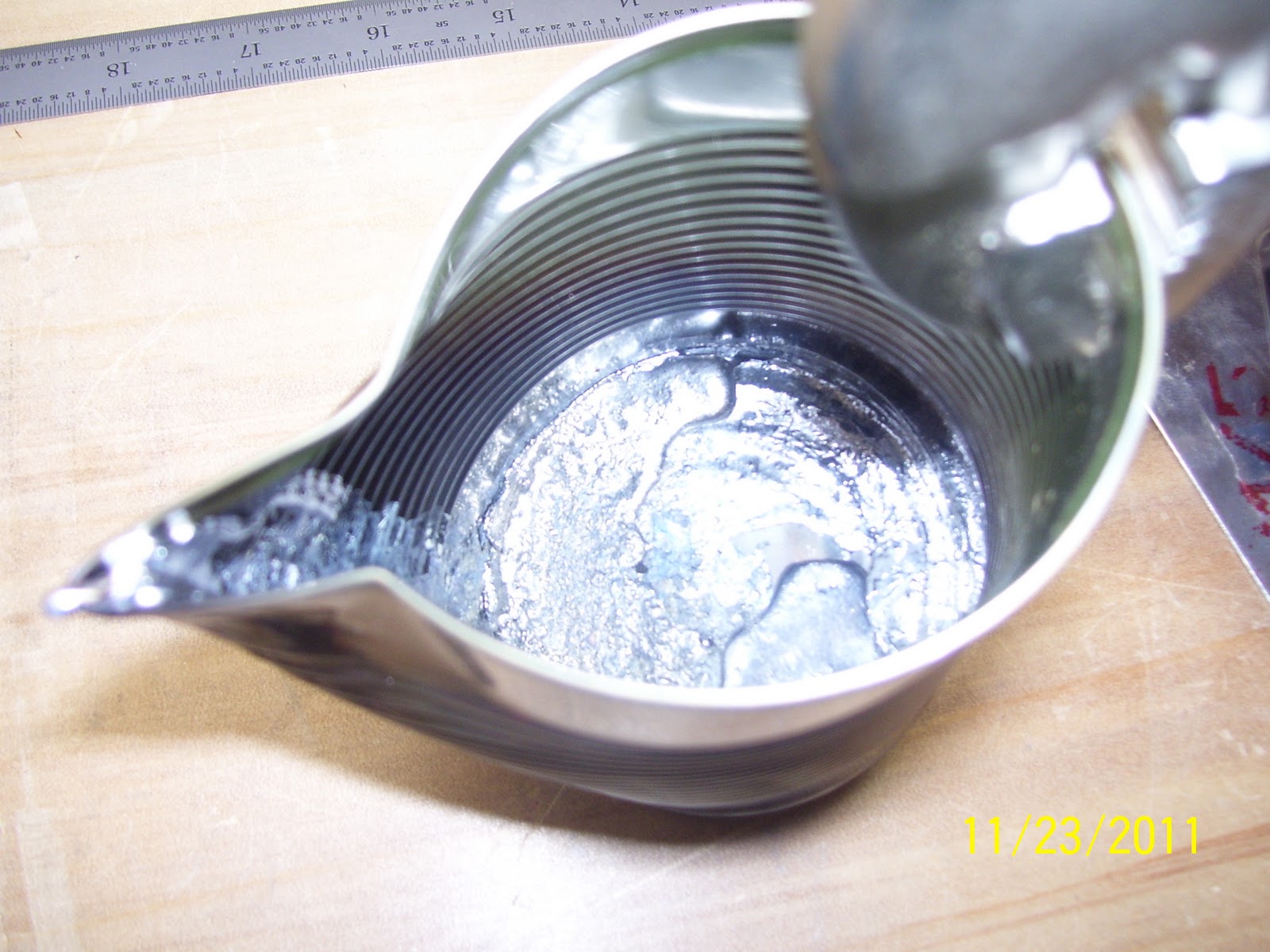
First is my smelting pot  - the olive can bent into shape foe melting/pouring the lead:

The lead counterweight, dog dish, and dirt, after the pouring had been done. Note that there are no holes in the lead any longer, after spending over an hour drilling them out the other night. I love progress! Not shown is the aluminum foil that I had wrapped around the entire part and cut the holes out so that lead would only end up going down the holes and not globbed all over the rest of it.


This is the inboard side of the trim tab, marked 1/8 inch inboard of the true cut line. I ended up cutting the tabs off right to the cut line and deburring them on the scotch brite wheel. Two hands on the dremel tool adn careful cutting here.... Really trying hard to make this a one-trim-tab effort.


Next is the line to cut the tabs off of the elevator. There is some detail about this in the plans worth mentioning here. Question is where do you decide to draw the line, and based on what reference? Answer is that the plans say to place a square angle up against the trailing edge of the elevator where it is cut out for the trim tab, and draw a line perpendicular  to that line for the "bend" line (in my case it is a "Cut" line). All fine and good, but you still don't know exactly where to draw the line - without carefully revewing the plans that is.

What I did is measured the length the trim tab skin at the leading edge - came out to about 17 and 22/32 inches. I then transferred that measurement from the inboard trailing edge of the elevator, outward that same distance, and made a mark. I then took the square, aligned it with the TE of the elevator, and drew the line across the tab on that mark.
This should allow the skins from the elevator and the trim tab to just butt up against each other, but you don't know for sure until you get the trim tab clamped into place.

Only problem with this is, when I look at other sites where people have bent the tabs over, the gap in the strain relief cutout at the bottom and top of the two above pics is MUCH smaller than what my mark indicates. IOW, the bend line is at a point that is actually a bit longer than the line that I drew.

Back to the plans to sort this out - Van's calls for a MINIMUM gap between the trim tab and the elevator of at least 3/32 inches to prevent the possibility of the two components from binding while under normal flight loads. So when I add that distance to my original measurement, it then looks much closer to the bend line I see in other builders logs. My approach was to go ahead and cut the tabs off the trim tab skin flush to the outside edges, since this is the final bend line that is called out in the plans for the trim tab. I then left a healthy amount of excess material on the elevator so that I can trim it up only as necessary once I start fitting the trim tab in place to achieve the optimal 3/32 inch clearance. Don't want to cut too much off and end up with too wide of a gap, which will add drag and not look very professional either. This is actually another plus for choosing to install the riblets instead of bending the dreaded tabs, because you can cheat a bit by moving the webs of the riblets on both the elevator and trim tab in or out to create the correct gap. Just have to be sure to maintain proper edge distance for the rivets that will insert into the flanges of each riblet.

How did I cut the tabs? I used the dremel tool and the reinforced cutoff wheel just as before:


First cut finished, next step is final cut and debure the edge so it is flush with the edges on both ends of the tab.
Pieces after the initial cut was performed
The last pic above shows the dremel tool and flex cable/cutoff wheel setup. What is not easily seen is that I have a 2x4 block of wood between the elevator skin where the clamp is located. I did this to provide some rigidity to the elevator skin where the tabs are located. You do NOT want the skin flapping around while you try to cut these tabs off. The tabs on the trim tab skin are relatively easy to do, because they are on the ends, but the elevator tabs are surrounded by vital areas of the elevator skin that cannot be compromised, or you will be purchasing a new elevator skin. So utmost care must be taken when trimming the tabs from the elevator. Both hands on the dremel tool, moving slowly as you get closer to the TE of the elevator. If you are worried about this, you can cut it up to a certain point, adn take a pair of snips or cutters to remove that last portion nearest the elevator skin.

Next you can see the inboard bottom trim tab edge, all cut and deburred, with the trim tab servo push rod control horn clecoed into place. This is the attach point of the clevis from the trim tab servo to the trim tab that will make it go up and down.

I read a post on someone's builders log that has me pondering this a bit. He pointed out that the two halves of the control horn are not riveted together for some reason - instead, each half of the horn is riveted separately to the skin. Yes, they do butt up against each other fairly well, but he pointed out that this is a potential collection point for moisture, and is therefore susceptible to corrosion over time. For reasons  I have stated in previous posts, this is not an area where you want to take chances or do a poor job of completing the trim tab. It can cost you your life someday, so it warrants careful consideration for preventing moisture from getting in between the two halves of the control horn. Suggestions are to use proseal, which I have none of yet, prime it, seal it, RTV, etc. I will put primer on these parts but I am not sure that this will be enough. Even more curious is why Van's does not to rivet the horn halves to each other. I find this quite strange for such a highly concentrated load point where the pushrod attaches to the horn.

Note the top of the pic where the clevis and the attachment pin have been inserted into the hole at the front of the horn. I also deburred this hole but did NOT run a drill bit through it. The last thing you want to do here is to enlargen the hole where the clevis pin is inserted. You do NOT want excessive play here or it may lead to problems trimming the airplane later on. Some folks choose to insert a cleco in here as well. I chose not to do that either. The clevis pin needs to just fit inside the hole adn be somewhat snug, but not binding

Lastly, here is a pic of the flop tube I received in a previous parts order from Van's:
I spent a considerable amount of time studying the plans for the wing tanks so I could understand how the flop tube assembly differs from the standard fuel pick up line assembly. the flop tube does exactly what it implies - it will "flop" from top to bottom and from side to side of the fuel tank so that when I am upside down and making cork screws in the sky, the engine will still be able to draw fuel from the tank. My system will contain one flop tube in the left tank, while the other tank will have a standard fuel pickup line, so all aerobatics will be done with fuel selected from the left tank.

I then studied the plan diagrams that show the plumbing of the fuel system into the fuselage. I now think I have a fairly clear understanding of how the fuel pickup lines and vent lines are routed through the fuselage from the wings. Amazes me how many 90 degree bends there are in the lines and fittings. If I did that in a 2 cycle RC airplane engine it would not stand a chance without some type of pump system in place. I guess the RV is the same way, in that I think it will have three fuel pumps installed - 1 auxiliary pump for each tank, and the engine driven fuel pump.

Hoping that my parts arrive today - Black Friday. Next steps are to drill and coutersink the trim tab front spar, elevator rear spar, prime the inside of the trim tab skin, bend the trim tab skin TE, align and drill the holes in the piano wire hinge, and fabricate the three riblets. Lots of stuff to do, but none of it overtly time consuming. Also read up on the hinge placement. Turns out to be another area where Van's is severely lacking in detailed info about this. A lot of confusion about how to mark the holes in the hinge, and the sequence of drilling, dimpling, and countersinking that must be done in the correct order to get it right. Study every detail in the plans, think it through, and it should come together just fine.....

Tuesday, November 22, 2011

385 hours on the hobbs - learned how to smelt lead today

I decided to try to fill the two previous drilled holes in my lead counterweight so I could start over and redrill them after my replacement parts arrive from Vans hopefully tomorrow. To do this I had to melt some lead and pour it back into the holes that I drilled the other night.

My wife's side of the family always has Thanksgiving te week prior to the official holiday, and this year it was at my house. So lucky for me this meant that I had my pick of tin cans to choose from for melting the lead. I chose a small can of olives, washed it clean, dried it thoroughly, and then pondered how best to try to accomplish this, since I had never done anything like this before.

I started by stripping off the paper around the can, then bending a pour spout in the top of the can so that I could direct the molten lead to the correct point and not make a total mess. Then I tried inserting some of the drill strands that I had saved from the first counterweight that I fabricated for the right elevator. I put the scraps in the can, the can in a pot, and the pot on the stove, and turned on the heat. This did not work so well.The lead only half melted and would not get to a state where it could be poured.

I guess I should cover the other part of the preparation. I wrapped aluminum foil around the counterweight, leaving only the holes on one side exposed where the molten lead would be poured. I then took one of my dogs water bowls, filled it with dirt, and placed the couterweight inside the bowl on the dirt. This is supposed to act as a foundation for the mold, and also to help disperse the heat. I then took a set of locking pliers, donned some heavy leather work gloves, and attached the locking pliers to the edge of the can on the opposite side of the pour spout.

So now I had to figure out what to use to heat the lead? I also figured that I was going to need a bit more lead than just the scraps that I had collected. So I remembered that I a propane welding/soldering torch, and I also remembered that I still had the large slab of lead that was trimmed away from the right side counterweight. So I threw the slab in the can adn lit the torch and started heating things up. This did the trick. The lead melted after a minute or so of direct heat on the bottom of the can. I quickly poured it on the counterweight in the dog dish. Man it comes out fast!. So I had to do some trimming to remove the excess, but all that ook was a coping saw and a few cuts to break it free.

Now my only concern is that the lead has definitely filled the old holes, but it does not seem like it attached itself to the existing lead that surrounded the holes. So in essence all I may have done is to pour a couple of plugs to fill each of the holes, and I am not sure how this will work out when I try to redrill them. Oh well, I guess I wil find out - hopefully tomorrow. If it does not work, then my options are to make a mold of the entire counterweight and repour the whole thing, or order a new counterweight for 17 bucks plus a large amount for shipping due to the weight.

I spent other time today working on the parts for the frame and studying the plans for the Wings. Match drilled the elevator ribs to the spars, and countersunk the designated rivet holes per the plans. Will make final decisions/measurements for the Wing jig tomorrow.
Monday, November 21, 2011

384 hours on the hobbs - another step forward and two steps back...

If it was summer time in Colorado, perhaps having these difficulties would not matter so much to me. But when you have to fight the cold and the wind outside, it just makes these little dips in the road that much harder to take. The step forward was bending the trailing edge of the left elevator yesterday - very much a non-event, and everything turned out as expected. Dare I say I think I have the hang of bending trailing edges now. Unless there is any bending that takes place during the fuselage construction (Longerons I think), I think that the only things left to bend are the TEs of both ailerons during the Wing construction.

Here is the elevator skin in the bending brake, with the forward spar clecoed and clamped in place to serve as a reference for when the bend has gone far enough.
I clamped the center portion of the spar to the skin since you cannot get clecoes in the rivet holes in that area because the web on the spar is not wide or tall enough to fit clecoes inside the flanges.

I am including this next pic as a "Don't do this" photo when you bend your trailing edges. Do NOT place the end ribs on either end of the spar prior to bending the trailing edge. I did remove this rib prior to bending. I only put it there to help stabilize the placement of the forward spar and to check the angle that I was looking for at the root after the bend was completed. If you leave it attached you may not get the correct bend in the skin and that would be bad and possibly expensive to fix:

And here is the tip after the bend. The nice thing about bending this skin is that it is MUCH easier to bend than the other skins, since just under half of the trailing edge has been removed for the area that will be populated by the moveable trim tab. ON the other hand, it does make this a bit more awkward because you have to double check to ensure that the edge is positioned exactly where it needs to be, which is a bit more difficult due to the loose skin flopping around on the inboard side.
Notice the duct tape on the edge of the tip to keep the bottom skin from sliding forward as much as possible, and the flush edge up against the hinge line. This method has worked well for me thus far. There are all sorts of other posts out there talking about using 1/8 inch dowels to keep the proper radius of the TE, or placing the edge a certain distance forward of the hinge line, etc. I have found all of this to be unnecessary. What I did do was tape down both bottom edges, added a 2x4 in front of the brake and under the skin to help support the bottom skin that hangs out of the bending brake so as to prevent the bowing of the bottom skin, and  placing the edge right up against the hinges before starting the bend. Works well enough for me.

Here is the shot from the right side. That curved tab will get cut off later.
Close enough from the top of the forward spar for me. The slight bow in the pic below is known as "ballooning", and if I really wanted to, I could keep trying to work that out until it was completely flat, but I don't think that this is necessary. Van's says to get it on top of the spar or "close" to it, so that there is not excessive stress required to hold the skin onto the spar. Strangely, this is exactly the opposite of the way that the skins for the Horizontal and Vertical stabilizers are applied to the frame. They are bent from the front side and attached to a spar at the back, so those skins are supposed to be stressed by design I guess, and they must be held down with clecoes to keep them from springing back up again.
Pic is a little confusing because the right elevator is sticking up in the back ground. So for clarity, these pics show the elevator from the front, with the forward spar web standing vertically, and the top left elevator skin shown draped just above the top edge of the forward spar flange to show where the bend ended up on the front side. If that fails to clear it up, just use your imagination! :)

Looking at the bottom side after the bend:
A blurry pic of the root end of the bend. I was still looking for about a 1/8 inch radius for the final bend. You will find that to get this raduis you will need to force the brake down to the point where the stiffeners from each side of the skin just start to contact each other. As long you do not forcefully smash the skin down to this point, and simply keep applying constant, steady pressure on the brake until this happens, you will end up with a nice crisp bend in the TE, which is what you want.

this bottom skin above looks a little bit bowed, but that is because it is sitting on top of my foam pad with no other structural support. So don't be fooled!

Next, I drew lines on each of the tabs that are going to be cut off. I marked them where the bend lines are supposed to occur, which is parallel to the line of the rest of the edge of the trim tab and elevator per the plans. I will then add another line about 1/8 inch further outward toward the end of the tab from each of these lines to ensure I have enough excess material to trim to final size after the hinges are installed on the trim tab and it is positioned on the elevator.

And now for the "2 steps back" part of this post. With the elevator skin bent successfully, time to work on the tip rib and drill that pesky lead counter weight.

Here is the rib assembly clecoed for match drilling onto the forward spar. Same way that was done for the right elevator.

Problem came after drilling the lead counterweight. I found a builders web site after completing the right elevator that mentioned the use of the drill press, and what seemed to be a better approach to drilling out the counterweight and corresponding holes in the counter balance skin and the forward flanges of the E703 and E704 tip ribs. The steps were basically to attach the rib and counterbalance assembly per the plans, but instead of free hand drilling the lead with the hand drill, simply mark the holes on the lead with a sharpee where the pilot holes on the front of the counter balance skin are located. then you disassemble everything and put the lead counterweight on the drill press and drill the holes to size. Then you put it all back together again and final drill the holes on the counter balance skin and then finally all the way through the lead weight and onto the forward flanges of the two ribs. Doing it this way seemed as though everything would line up just perfect, right?

Well, I think my big screw up may have been setting a 2x4 on the vise on my drill press so that it was level according to my bubble level, instead of ensuring it was PERPENDICULAR to the drill bit. I think this actually created an angle other than 90 degrees between the lead counterweight and my drill bit. Long story short, one of my holes in one of the ribs turned out to be just wide enough for the washer and the nut to be placed on the forward flange of the tip rib, similar to how it turned out on the right elevator.

Unfortunately, the hole I ended up with on the counterbalance rib flange was way too far inboard. Result - part ruined, hole dimensions in my counterweight are now suspected to be incorrect, and I need to order more parts and then ultimately learn how to smelt some lead to fill the holes in the counterweight and start all over again. I was too disgusted to take pics of this last night, so those will have to wait. Ordered a new counterbalance skin and counter balance rib from Vans today so should have those in a couple of days, hopefully before the holiday.

Next time I will do the following a bit differently:
1. Ensure that the counterweight is SQUARE to the drill bit instead of LEVEL to the ground - stupid me!
2. Drill a 1/16 inch hole through the lead counterweight on the drill press instead of drilling the final sized #12 hole for the screw. I will then take the counterweight with the small holes and drill through the entire assembly to see where the stupid hole will end up on the forward flange of the rib. At least this way I can tell how I need to adjust the hole, if at all, before I commit to drilling out a large hole and screwing up the hole thing all over again.

Once I know the hole is correct, I will disassemble the parts again and finish drilling the hole in the drill press.

And as a last thought before I close, let me be perfectly clear about the settings and drill speeds I used to drill out the counterweight on the drill press, which actually worked out pretty well:
1. I step drilled the counterweight just as I had done before. This allows removal of small parts of the lead without seriously bogging down the bit. I started with #40, followed by #30, #28, #21, #19, and finally a #12 bit

2. Drill press was set to 3100 RPM - as fast as it can go - I did not change it to a slower speed at all.

3. Used 3-in-1 oil RELIGIOUSLY for this. that means drill about 1/8 to 1/4 inch at a time, stop the drill bit, clean it off, re-oil the bit, drill another 1/8 to 1/4 inch, wash, rinse, repeat.

4. Technique to is be VERY SLOW with the press. I also would set the stops on the press so that the drill bit would not go all the way down initially. I would leave it about 1/8 inch high, and finish the hole by setting it down all the way once the drill had removed all the material down to that point.

5. Be sure to apply pressure to the press bar, and then back it all the way out to remove the slag. If you have the bit properly lubricated you should see small chips come out, and not see too many groove-filling slivers come up. Slivers are bad and may cause you to mis-direct your hole if you are not careful.

6. Took a while to do it this way, but the holes got drilled out as straight as my settings would allow.

Hard part about this is not being able to clamp the lead. If you try to clamp it you will distort its shape and will have to melt it down and reform and start all over again, or order a new one from Vans. This was even harder because my drill press caused the weight to vibrate quite a bit. Not so bad when you start out, but after the 2x4 got a bunch of oil all over it, it got very slipperly. I have a laser device on my press so I can keep a relatively good reference to the hole position and the drill bit. So I held the weight with my left hand and ran the press with my right.

Out of all the trials and tribulations I have endured thus far on this project, I would have to say that drilling non-pre-punched holes through multiple layers and thicknesses of dissimilar metal has to be the most challenging thing to do.

So hopefully that provides enough detail for those that may follow so that you don't screw yours up the first time around!