Tuesday, June 21, 2011

292 hours on the hobbs Final Riveting and Skin Preparation for Rudder

So it's been a few days since my last post, but I ahve been busy on the rudder. I am beginning to wonder if this part will ever get finished. Lots of tricky riveting to do. One of the other things that has to be done is to roll the leading edges once everything else is riveted together. Below is a pic of a controversial edge rolling tool from Cleaveland tools. I had ordered this with my tool kit and had done some practice pieces with it, but not with very promising results. Then I ran into a whole bunch of posts on VAF. I found one thread that clearly explained the problem. There is such a lack of guidance from the makers of these tools that nobody understands how to use them correctly. Even the hints for homebuilders video on the EAA web site does not show enough detail about how to properly use the tool.

As the pic shows, there is a large thin flange on the top roller. This fits right against the edge of the skin being rolled, and needs to stay in that position while rolling the tool. The other trick to using this tool correctly is NOT to set the depth between the rollers too close or tightly together. People think that you have to get this really tight on the skin to achieve the desired slight bend on the edge. In reality it just needs to be tight enough to allow the roller to EASILY roll along the edge of the skin. Everyone expects to see a noticeable bend in the edge of the skin, probably because the diagram in the picture in the plans provided by Vans shows this bend to fairly distinct. The fact is that the bend is barely visible to the naked eye when done correctly. The tool creases the edge of one side of the skin just enough to counter-act the tendency of the skin to curl up when the pop rivets are applied. Most builders are complaining about how they cannot move the rollers, or how wavy the skin edge turns out, or how uneven the rolled edge is because it slips away frome the edge while being rolled. ALl because they are not using the tool correctly.

The fact is, if you use it correctly, it leaves a nice, even, small crease in the skin, exactly like it is supposed to.

Here is a set screw to make certain that the depth of the rollers stays set exactly where they need to be


And the Top roller that shows the flange that is kept flush against the edge of the skin, adn also shows the tapered part of the roller that actually apples the bend to the edge of the skin....


A bad pic attempting to show the gap between the rollers after snugging them up against the skin so that they were firm but not tight or smashing the skin.

Another not so good pic trying to show the edge of the skin after rolling was completed. You can just make out a slight bend on the edge. Again, you only roll the skin edge that will overlap the other skin. You do NOT roll both edges.

Many more pics to post, but it's late, so I will finish catching up tomorrow. As a preview, I will post pics showing the method I used to set the remaining 6 rivets on the edges of the support bracket, putting RTV on the stiffeners before closing up the skin, and a mock up/test tool that I created for practicing the rolling/bending of the leading edge of the rudder...

Sunday, June 12, 2011

283 hours on the hobbs - Rudder almost completely riveted

I'll get more pics of this weekend's progress posted tomorrow. For now I will continue the previous post and show pics of the tip rib installation. Below is the setup that I used for just two rivets to attach the tip rib assembly to the top of the main rudder spar. I used the R717 straps that I fabricated for the bottom rudder as supports, and used my cleco clamps to hold it all in place.

I had originally set this up vertically in much the same way that I did to rivet most of the bottom rib assembly to the spar (see my previous post). Then I realized that this would NOT allow me to run the rivet gun and bucking bar the way that I wanted, so I switched gears, disassembled everything from the vertical support, and clamped everything to the smaller work table. This worked out MUCH better. The problem doing it the other way is that the rivets were not in a good position for me to access them properly with the rivet gun and the bucking bar. I need to have the rivet gun in my right hand and the bar in my left to rivet correctly. The manufactured rivet head in this case needs to be against the small flange of the spar in order to allow the gun and rivet set to apply pressure to the manufactured head of the rivet, which in turn pushes the parts closer together. I have had way too many other past experiences where I have NOT done this correctly, and I wanted to try very hard this time NOT to make the same mistakes.
I used my offset rivet set and the thin man tungsten bucking par to set these two rivets. Worked out beautifully. The spar flange is flush to the rib web, and there is no buckling or curling of the spar flange after driving the rivet.

A shot that shows the reason you need to use the offset rivet set. Shown is the main rudder spar on the bottom, and the rivet gun in position with the rivet head firmly seated in the rivet set(just out of frame on the left side), Notice how close the gun and set retaining spring are to the spar web. The offset, or slight bend and rebend of the shaft of the rivet set, allows for just enough clearance for the entire rivet gun to clear the parts.


And a shot of the other end that hows the rivet set firmly against the rivet head. You can just make out the separation line where the small spar flange butts up against the tip rib web. This is the correct process to set these rivets because it forces the two parts together when you apply pressure to the rivet set as I stated earlier.

With the frame all riveted together, it was time to cleco the skin to the frame and get this baby riveted. After a lot of squeezing, I only have about 8 rivets left to go, which include the 6 rivets on the sides of the R 710 support bracket on the bottom of the rudder, and the 2 bottom, most rearward rivets attaching the bottom rib to the skin. I intend to use standard flush rivets on these holes if I can work out my back rivet process correctly with a small enough custom bucking bar. If not, I will use the pop rivet alternative that is listed in the plans, as many other people do. More pics tomorrow! ALMOST THERE!


Saturday, June 11, 2011

268 hours on the hobbs. Rudder Frame Riveted

Man where to begin. there are so many little decisions involved in this process to properly get the Rudder frame riveted together correctly that I could write an entire book on the subject. I relied heavily on posts and kit logs from others to assist me. I guess I'll just caption the pics as best I can, since I took a ton of them to cover this process. As you all well know by now, I like the details - it is part of my "persona" that makes me who I am - different from everyone else. Alas, when it comes to finding additional info from others about the rudder final assembly, all Iam able to find are some generalized comments that usually only tell part of the story, and even fewer pics are shown that clearly cover some of the "gotcha" areas of this assembly.

So here is my attemp to alleviate some of that:
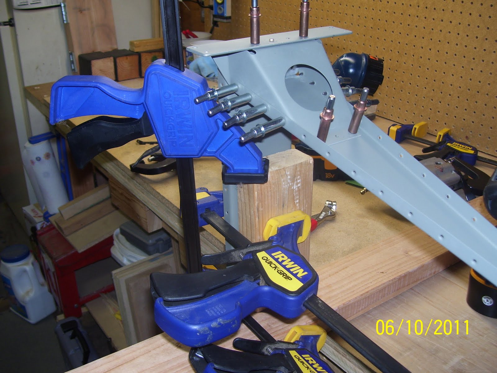
Step one - take the main spar and  - - what is my first rule of airplane building - - right - ALWAYS SECURE THE WORK! This is the main spar tipped upside down along side my work bench with the bottom rib and control horn already riveted in place.It also shows the R710 support bracket that is clecoed into place. I chose this configuration as the best method for securing the work since it gave me the best "all around visibility and access for setting the rivets in this complex area.

If you have smaller or more mobile work benches than mine, that will be a plus, because you will be able to move the work bench around to more easily position the work. Unfortunately, I had to figure out how to set things up without moving my benches all over the place, since mine are not so mobile. I basically took a spare 2x4 and screwed it down into my work bench, close to the pegboard, to provide a stiff support bracket for positioning the rudder frame. Then I used other combinations of wood to clamp the spar in place so that it would be rigid enough for riveting. You can never have enough clamps.


Tools - so what to use to set the structural rivets for the R710 support bracket? I chose the hand squeezer, a flange yoke, and both a half inch x 3/8 inch flat set and the 1/8 inch cup set for the AN470 rivets. Many posts indicated that the flange yoke and the 1/2 inch flat set are required for this assembly, and they are quite correct. The hand squeezer is lighter and allows more control than the pneumatic squeezer, and the longer flat set is needed because you need an extension to be able to reach the rivets that are inserted above and behind the big round hole in the support bracket.


This is where it gets interesting. A tip I learned from a VAF post a while back is that the rivet call out in the plans essentially provides the direction of insertion of the rivet. The manufactured head (in this case the round head of the rivet) will then be in the proper position against the proper part, and the rivet shaft will also be in the proper position for bucking the shop head. The general rule is to place the manufactured head against the thinner piece of metal, and set the shop head of the rivet against the thicker piece, to prevent curling or gapping the thinner metal. Otherwise, follow the plans.

So what I found in many different posts covering this assembly is that many people are putting the first four rivets with the manufactured heads out, or against the R710 bracket, but the ones that are following directions correctly by placing the round head underneath, so that the shop head is visible and can be easily checked to ensure that it was set correctly. So how then, you may ask, does one insert the rivet up underneath the bracket and into the hole? You cannot see the hole since it is hidden behind the bracket, so it is an entirely blind process. I found it "interesting" that nobody seems to comment about this. So, my solution, after thinking about it a bit, is shown below - I reverse-wrapped a piece of masking tape to the top of my finger (sticky side out) and then stuck the round head of the rivet on the tape as shown, I then I slid my finger into the large access hole in the bracket, and positioned the rivet until it could be pushed through the hole. Then I simply removed the tape. The rivet, although inserted upside down, still managed to stay in place rather nicely due to the close tolerance of the drilled hole and the rivet shaft.

And here is the rivet after being inserted upside down into the hole. This, by the way follows the general rule mentioned previously (manufactured head is against the thinner metal) and also complies with the rivet callout in the plans from Vans. So all you other folks that are doing it differently - -you are doing it WRONG! Notice that I started with the two center rivets, setting them one at a time with the hand squeezer, which is another tricky procedure.......

Riveting in progress. This is  a similar pic to those from other builders in many other posts. What is not ever mentioned or shown is just how difficult it is to get the yoke into the proper position to insert it inside the support bracket, and then make certain that the cup set is sitting squarily on the round rivet head, which is all hidden from view. Several tips listed here to hopeflly benefit other builders that will visit this site...
1. Before inserting any rivets into the parts, setup your squeezer by taking a rivet and adjusting the set-depth to the correct level. You want at least enough depth to initially set the rivet to hold it in place, and not so much that you risk over driving the rivet. I always start small here and gradually increase the set depth after I see what is happening to the shop head of the rivet. I may do this 2 or three times until the rivet is correctly set.
2. remove the center clecoes, and when inserting the other end of the yoke into the hole, do it straight on from the center, but at an angle as necessary that follows the contour of the support bracket, if that makes sense. It is a tight fit regardless, but it can be done.
3. When squeezing, make certain that the flat set is positioned as close to the center of the rivet shaft as possible, and that the squeezer is held as straight up and down as possible, so that it is perpendicular to the surface being riveted. This will ensure that the cup set will slide into the correct position over the hidden round head of the rivet, even though you cannot see it. The access hole will provide just enough clearance to set the rivet without bending the bracket as the squeezer is actuated. 

If you do these 3 things, then the rivet will be set correctly on both ends. 

And this is me playing Airworthiness inspector with my little mirror so that I can peak up underneath the support bracket to inspect the round heads of the four rivets that I just set. That little mirror can be manipulated to inspect all sorts of things, especially when used by somebody that knows how to use it. I mainly wanted to see that all the underside rivet heads were sitting flush against the metal, and that they were not deformed in any way. All of them looked fantastic.


And here are the other three rivets on the back side of the bracket that attach to the rib. Much easier to get to and to set these rivets. Now that the structural rivets are set, only the flush rivets on both sides of the support bracket remain. These are not set until the skins are attached to the frame, so don't make that mistake either! Just remember to take your time through this entire process. Next I riveted the tip rib to the main spar.

Tuesday, June 7, 2011

Floors and more rudder pics

I neglected to add a couple of "finished" pics of the floors, so I am including them here. Living room all cluttered up with stuff again, with floors and area rugs in place. Including son # 2 in prime TV-watching postion on the couch.


Finished stairway. What a pain this was. The stair nose molding had to be special ordered and was super expensive to boot. The top stair had to be trimmed and the carpet re-tacked in place. Almost as tedious as building your own airplane, if I do say so myself. I guess a good thing about it is I got real familiar with my new dremel vibrating saw and sanding tool.  This was pretty much the last thing that I did to complete the floors, because I knew it would take a fair amount of work to get it done.


And the tile landing with the the trim and grout in place.


OK - enough about floors. How about some rudder pics! Here's the Rudder after masking both the inside and outside in order to finish priming the forward flanges and the top and bottom rib attach areas, which, as I stated in previous posts, I should have taken care of BEFORE I bent the rudder skin.


Shows the forward rudder flanges after priming was completed. The masking job, although quite time consuming, worked out fairly nicely.

Next is the top or tip rib with the counterbalance skin riveted in place. Note the clecoes holding the aft part together. These hles are not riveted yet because this is where the rib assembly will attach to the skin in a later assembly step. Note the lead counter balance in the front of the rib. This actually works by "countering" the weight of the control surface on the back side of the hinge line, with an equalizing counter weight on the forward side of the hinge line, so that the surface basically desires to return to the neutral position after being displaced. It  makes the controls much easier to move, the airplane much easier to handle, and makes it safer at higher airspeeds.

I guess some folks recommend leaving the  outerskin off the rib until AFTER riveting the rib to the spar, since they use the pneumatic squeezer on these rivets. One thing I have learned about my own riveting skills along the way is that I do much better when bucking the structural rivets of ribs onto spars than when I try to use that blasted heavy awkward pneumatic squeezer. So I will buck these rivets to the spar as well. So no problem putting on the outer skin for me.

A very poor pic of the notches I drilled on the lead counterweight in order to clear the shop heads of the rivets along the inside of the rib. I used a number 12 drill bit for this, and carefully  gouged out just enough material for the needed clearance. After everything is painted I may even need to add more weight to this area to re-balance the newly painted surface.

Yes this is extremely important. Just recently the Canadian equivalent of our own NTSB in the USA released a final report on an accident involving a Canadian registered RV-7A that suffered structural failure in flight. ONe of the findings was that there was no record of the control surfaces ever being balanced at all, either before or after painting. This may have played a roll on the incident, so I will be paying very close attention to this aspect of the build with every control surface.

Shows the rivets in relation to the counterbalance and the clearance that was needed, especially on the left front side. The counterbalance is bolted to the assembly through the two big holes in the middle. This is removed during final assembly of the rudder to make it easier to handle, and re-attached when the rudder assembly is finished. The remaining portion of the counterbalnce skin will be used as attach points for the fiberglass tip later on.


I used a number 10 countersink bit to countersink the bottom of the lead weight so that it fits flush against the rib web and the dimples for the screws.


Rudder control horn attached to the bottom rib and the main spar. note the scuffed area where I had to debur a gouge caused by the bucking bar while attempting to set this rive the first time. I will reapply primer to this area later. Also note the riveted nut plate in the middle of the assembly. This is where the rod end bearing is inserted. This bearing is the pivoting point of the rudder that slips between the hinges on the VS. There are three of these for the rudder.


And the other side of the same area. Note the scuff mark on the bottom for the same rivet in the previous pic. I will re-prime that as well.


The nut plate and support plate for the mid-level hinge on the forward spar


And the support plate and nut plate for the top hinge. Note the deformed shop heads for the nut plate. Yes, I inevitably had to drill these out and and replace them too. I did that this evening. Now they are nice and round, but I also managed to bend the flange of the nut plate while pounding out the rivet, so I had to replace that nut place as well. Now I need to place an order to Van's for more nut plates, since I am short one, adn they did not seem to give me any extra ones like they do with the rivets... :(


Monday, June 6, 2011

Lots of progress on rudder but definitely out of practice! 264 hours on the hobbs.

I am kind of tired right now so will post a ton of pics tomorrow. I made a ton of progress this weekend on the rudder, but of course not as much as I had originally hoped for, as is always the case. In a nutshell, this is what I got done:

- Finished priming the rudder skin areas and all the rudder frame parts.
- Dimpled all remaining holes using the hand squeezer. I did NOT uze the pneumatic squeezer for this for several reasons, the most important of which is the fact that this is probably the thinnest skin of the entire airplane at .020 inches, and I did not want to risk screwing it up with the air squeezer. I have much better control with the hand squeezer and it worked very well of setting these dimples.
- Met with my friend and fellow builder Mike Rettig and his wife Aneta on Saturday at my location. They are edging ever closer to actually starting on their RV 10 Empennage kit. He helped me us the close quarter tool to finish several dimples in the rudder skin that I could not reach with the hand squeezer.
- Countersunk the underside of the lead counterweght with a number 10 countersink bit, so that it will sit flush to the web of the R703 tip rib after it is bolted down. I also had to partially drill out the sides of the counterweight in two places to allow clearance from the shop heads of the to most forward rivets along each side of the R703 tip rib that attach the R713 counterbalance skin. I used a number 12 drill bit to create a hole (a shaft actually) with a large enough radius to allow clearance from the shop head of the AN426-3 rivets. That did the trick. ALl other shop heads of other rivets appear to clear the lead counterweight with no problem.
-Spent several HOURS locating adn reviewing a series of posts on VAF that discuss drag or friction torque, and the importance of adding that to the torque values given in a special table provided by the AC 43.13 bible of aircraft building and repair practices. What a pain.
-Test fir the lead counter balance block to the R703 tip rib, and torqued the screw down to initial specs (25 inch pounds) to verify that the countersunk holes were drilled out correctly.
- Riveted the counterbalance skin to the R703 tip rib. I even had to drill out 2 rivets that I had told my self I would NOT install per the plans before I got started, but I ended up setting them by mistake anyway - what a pain!
- Today I managed to get most of the frame riveted. I took some advise from another builder friend of mine, Steve Riffe,  that I was able to utilize to my benefit (Thanks Steve!). He had learned the hard way that the -5 rivets that attach the support plates to the main rudder spar for the rod end bearings are a bit too long, and he tried to use the pneumatic squeezer on those with less than desireable results. The rivets kept bending over. He had to drill them out and ended up bucking them with the rivet gun. I used the rivet gun from the get go, but unfortunately I did not quite get off scott free either. I buggered up one -7 rivet, and my special AN470 drill out tool failed miserably to find the center of the rivet head when I attemtped to drill it out. Although the support plate was partially incorrectly drilled out as a result of this, I managed to salvage it, and was able to finally get the rivet shank out and reset it with a longer -8 rivet to fill the slightly larger hole that resulted from the rivet removal.

Next steps
- I need to replace the two rivets that attach the nut plate to the top support plate R608, finish riveting the tip rib assembly to the spar, and finish riveting the R710 support bracket to the bottom forward part of the rudder, and then I can finally start zipping up the skin onto the frame. Then comes rolling the leading edges, installing the rod end bearings, and finally attaching the rudder to the VS to verify that it actually moves like a rudder. Seems like it just never ends.....

All in two days work! A ton of pics will follow tomorrow!

Tuesday, May 31, 2011

Back on the build again

After having dusted off most of the rudder parts, I am happy to say I am back on the build again. I did not manage to get a whole lot done over the holiday weekend due to my son's graduation party, but it's a start at least. I managed to get the remaining portions of the rudder skin roughed up for priming. I know I mentioned this some time ago, but don't foget to prime ALL of the necessary areas of the skin BEFORE you do any bending. It will save a ton of extra time.

All parts have been re-cleaned. I just need to fnish masking the inside and outside of the skin so I can shoot it with the NAPA 7220 primer. I will most likely prime the frame parts with the other more expensive primer. Don't know why - just a personal preference here. I have also deburred the edges of the rudder skin. I made a sanding stick to aid with this by taking a 1/2 inch square piece of wood by 12 inches long, and using a glue gun, I hot glued some aluminum oxide 220 grit sandpaper to the wood. I find that I like the results of using the sand paper much better than using the edge deburring tool. You have to be careful or you risk scratching the exterior surface of the skin if you slip, so take your time.

Looks like I will also need to setup the C frame table one more time to finish dimpling the skin.

The goal will be to finish the rudder completely by or before this weekend.

Saturday, May 28, 2011

Wood Floor Project Finished

After a long 2 month departure from the airplane building to address a rather large home imporvement project to install wood floors in several rooms of the house, I am happy to report that this latest "interruption" is finally finished. Having never done any tile or floor work before, it was almost as daunting as my decision to start building the airplane. Several hundred questions and discussions with the local flooring store employees later, and after purchasing many specialized tools (sound familiar?), I managed to do the deed.

So, this post is a bit of a departure from the usual subject matter of building the airplane, but I will reign it all back on topic by simply saying that the garage is now back to airplane building mode instead of wood flooring cutting mode, and I am in the process of wiping down all the wood dust that fell on EVERYTHING in the garage. This was my only real mistake - setting my chop saw up so close to my work benches.  The laminate flooring I selected was made with MDF, which I am also using for backer boards on the bench for drilling airplane parts. Now I ahve a much greater appreciation for what happens to this stuff when it is cut. The dust goes everywhere.

The project started with a new tile landing in the entry way, followed by new floors in the living room and kitchen, and the main hallway leading to the bedrooms. Pics that follow show the tile and various stages of the wood fooring as it was installed. This was a true family project - with everyone participating in various capacities. I followed many of the same processes and preparation that I us in building the airplane, such as setting up the garage with several saws and other tools to get the job done, making pain stakingly accurate measurements of every inch of my floors, ensuring the proper amount of material was determined, etc.

I am relatively pleased with the results, but at this point I am really itching to get back to the airplane build, so I am just glad that is it finally at the point where I can call it officially finished.