Showing posts with label Wing Leading Edge. Show all posts

Sunday, January 17, 2021

Restarting yet again - a year and half later

 Hard to figure out exactly where to start this Blog again. Recap - I screwed up the inner and outer skin of my left wing LE Mode in April of 2019. Tech Counselor came out and we discussed using a planishing hammer and dolly to reform the damage to the outer LE skin and inner subskin. I bought the hammer and the dolly, and was about to attempt the task of re-forming the skin, when I had yet another epiphany. 

1. I realized that positioning the dolly had to be done exactly right in a very tight spot inside the LE, and I determined that this would just be next to impossible for me.

2. After having a very honest conversation with myself, I also realized that even if I managed to reform the skins correctly, this mod went wrong almost from the start where I did not create the wood form blocks for the sub skin properly. This meant that curve of the LE of the subskin has NEVER been formed exactly as it should, and leaves a gap between the outer Le skin and the subskin that then causes issues with how the removeable plate would sit when screwed onto the subskin. It also puts additional stress on the rib flanges underneath. IOW, the removable plate will NEVER sit flush the outer skin because of the subskin deformity, and the added stress in the rib might lead to other structural problems later. I should have taken much more care and ensured that the wood form blocks I used to bend the subskin EXACTLY matched from the curvature of the LE Rib so that the radius would have mated with the LE skin correctly.

3. The final straw for me was the realization that, after seeing it all come together, there was a much easier way to approach this whole thing, without the need to use the massive subskin and all the forming, measuring, bending, cutting, laying up, and riveting that was involved. I also realized that I could still attempt this mod AFTER the plane was built per the plans that would take very little time, and could be done using much simpler techniques than my original design.

As a result of this, I decided to abandon the entire mod and order the necessary new parts, including a new left wing LE skin and some ribs to build a stock LE. The only thing I will still do differently is order a left wing LE skin from Vans WITHOUT the cutout for the stall warning vane service access plate. 

It is sad to have spent so much time and effort on this, only to reach the conclusion that I need to abandon it. It is even more sad to come to this decision only after assembling and almost completing it.  However, I am not sad about having made the attempt, as I learned tons about airplane design in the process, and I now have a very deep appreciation for those that undertake the challenge of designing airplanes from scratch. So my only regret is the time I have lost, but nothing else. Basically it was not until seeing entire mod coming together to figure out that there was a much easier, simpler, less invasive and less time-consuming way to do this. I'll keep the details of that to myself for now.

So what happened after all that?

Instead of working on the fuel tank as I previously stated in my last post, I spent the next couple of months working on some mods for my 14 inch RIGID bandsaw.  This saw became notorious for not being very well built to the point that it vibrated so badly that it was difficult to make fine, accurate cuts. With the forming of the forward Fuel tank mounting brackets looming in the distant future that would require the use of my bandsaw, I decided to spend the time to perform several well-documented mods to reduce the vibration and turn it into the tool that it should be. There are numerous You Tube videos on the subject and I watched all of them.  

I needed to purchase some new Neoprene tires for both wheels, some longer mounting bolts for the motor as well as the saw base itself, a custom cut piece of 3/4 inch plywood to fit over the top of the mounting stand, and some new composite saw guides. After much work on this, I ended up with a good saw that passes the "nickel" test, where you place a nickel on the saw table on its skinny edge, then turn the saw on. If the saw is balanced properly, the nickel will stay on its edge without falling over. I was able to achieve this to my satisfaction. 

The end result was that I could now cut the 1/4 inch thick Fuel Tank Angle Mounting brackets with reasonable accuracy on the bandsaw to reduce the amount of forming work to do after the initial cuts. One of the most challenging parts of the saw mod was the need to trim the 1 inch wide neoprene tires down to about 7/8 inches so that they fit in the wheel tracks properly. This required making a special wood frame and using my belt sander to trim the edges accordingly. That, balancing the wheels, and adding the 3/4 inch plywood base and a new composite "link" belt all contributed to solving the vibration problems with the saw. Unfortunately this was yet another delay in the build.

Then, my wife and I needed to take a much needed vacation together, so spent the next couple of months focusing on a multi-faceted trip the New York for the first time. We spent one week in New York City and did all the NYC things a newbie would want to do - Statue of Liberty/Ellis Island, 9-11 Memorial and Museum visit, which I highly recommend to any red-blooded American, went to a Broadway show, Times Square, Stood outside during a Today Show airing, had a real New York Pizza slice, learned how to ride the subway, went to Grand Central Station, Went to Battery Park, the Fashion district, visited the famous toy store FAO Schwartz, and much more.

Then we flew off to Buffalo and took a shuttle to Niagra Falls, Ontario to see the falls for the first time. We had so much fun there, and the falls were so beautiful, that we both want to go back someday. this all happened in early September of 2019. As the whole world now knows, only a few short months later all of New York and the rest of the world would be shut down and fighting for its life due to the COVID pandemic. I have not been back on the build ever since May of 2019 as the the wind just went out my sails after coming to decision about the mod, and too many other things got in the way. After  our vacation, winter and the cold set in yet again, and I still had no heat in my garage. 

Then COVID showed up in the spring of 2020, and the massive wild fires in Colorado soon followed, and it was a struggle to stay alive and to breathe through smoke and ash all at the same time. I almost lost relatives in the Troublesome Fire in Grand County - very scary. So airplane building was not on my list of things to do throughout that entire period.

I endured multiple furloughs and layoffs at work last year, only to find myself working 15 hours days, 7 days a week, for at least a couple of months. So you could say that yes, I kept my job, which was a good thing, but at great personal cost to my overall health and well-being.  Now we are in 2021, where winter is once again upon me, and still with no heat in my garage. What a wildly exhausting time it has been over the past year and a half. 

Is there a plus side to any this? Well, in the interest of counting my blessings, both kids have graduated college, have jobs, and are out of the house and successfully on their own. Several major financial burdens have ended, I have not contracted COVID nor have any of my family members, and COVID vaccinations have begun. Aside from politics and some extremely idiotic people in this world, it seems like the sun may be trying to shine on the world again. So I decided it is also time for me to re-engage with the plane project again. I need to order parts from Vans and finish the wings.

More to come..... Sorry for the long hiatus. Stay safe, respectful, and peaceful everyone. Life is too short. I'll have pics of the bandsaw mod, planishing hammer and dolly, and some other stuff in the next post.

Monday, May 20, 2019

Busy Preparing for the Fuel Tanks and Tech Counselor Checks out my LE

My Technical Counselor and former long time EAA Chapter 301 President Jim Elliot has been mentoring me through all this LE mod fiasco. I had to wait a couple of weeks for him to become available to come and visit the "almost" finished LE work, and he was finally able to come out last Saturday and take a look. He is a Mooney aircraft owner and has helped several people build different makes and models of experimental airplanes. He definitely knows his way around an airplane, and with evaluating potential affects of modifications such as mine. More on that in a bit.

Since I knew I had to wait for a bit for him to be able to come over, I started preparing (for about the third time now) to get back to work on the fuel tanks. So although I have not posted in while, I have still been very busy thinking, reviewing, and planning for re-engaging on the fuel tanks to get those behind me as soon as possible. his started with a review of many previous posts where I actually started on the left fuel tank because you needed to match it up with the LE to check alignment and drill some holes in the T-712 mounting brackets for the wing spar and the rear tank baffle. This little journey took me clear back to posts from the Fall of 2017. About the last thing I remember about the tanks was fabricating the tank stiffeners for the bottom of the fuel tank skin, and countersinking skin-to-rear baffle holes per the plans.

After reviewing the stuff from the past, I ended up coming up with a list of new additional questions that required answers from Vans. As a side note, to date I have order at least 2 proseal tubes, a small sized can of proseal, and a full sized quart of proseal - ALL of which have shelf lives that have long since expired, so they will not be used to seal any part of my fuel tanks, and I will need to put in an order for more proseal yet again. Sucks to be me I guess - that's about the only way I can sum that up.

Many of these additional questions are questions that you do not see either asked or answered by others, but I find it quite strange that others are not asking the same questions. Anyway, to make sure that I don't lose the content, I am posting them here for myself and anyone else following my blog that might also appreciate the info:

385b and c SW fuel senders - for left and right - is it correct that the potentiometer scale/meter on c version for the right tank will be reversed (facing forward instead of to the rear, when installed on the side of the tank, or should the scale for both still appear toward the rear of the tank when installed correctly.

Vans says this backwards orientation is normal - important thing is that they both point down when installed either on the end rib or the rear baffle plate.

Am I supposed to scuff the back side of the sender flange of each sender if I am going to proseal it directly to the tank rib (NOT use the rubber gasket or cork as recommended by many who have been there before.)

Vans says not needed.

The left sender seems to have a dead spot at the end of travel of the arm (empty indication) - either no ohms reading at all or much higher (300 ohms or more - much higher than expected 240 ohms per the plans.) The right sender seems to be indicating correctly per the palns info. Ordered both SW senders from Vans on 4-16-18 order # 74191. SW says has a 2 year limited warranty - how do I proceed with a replacement. Go through Vans or direct with SW?

vans - Contact SW directly to replace it

Left tank will be flop tubed, so sender will be in bay #2 in rear of baffle.
1. Did I do a lot of extra unnecessary work by cutting the big hole in the aft of the end rib, when I found out that the sender needed to be placed in the second bay via the baffle in the first place.

Vans   -still good to have access t that bay due to the trap door and the flop tube/anti hangup bracket attachments.

2. With the sender in the secnod bay of the rear baffle, that means that the only way I can service that sender if necessary is to pull the entire tank, correct?

Vans - correct - you will have to pull the tank to service the sender that is mounted this way

3. For tank baffle mounted sender, do I need to cut another big round hole in the second bay AND use a reinforcement ring (T-407) as well, or just the hole big enough for the sender to fit in?

Vans says nope - no reinforcement ring or big hole needed - just a hope big enough for the sender to be inserted/mounted directly onto the rear baffle plate web. No reinforcement ring needed because the baffle plate is thicker/stiffer than the rib web.

4. Do I need to use another reinforcement stiffener ring for the T-411 cover plate on rib T-703 if no sender is being mounted in that hole, or can I just mount the cover plate, with nut plates mounted on the rib web itself instead of the combo of the rib web and the reinforcement ring?

Vans - would still use the stiffener ring here as the rib is not very thick and alot of strngth is removed by cutting that big hole.

5. Depth of tank for SW sender specs to determine what size to cut the rod - what dimension should I use for that (tank depth so I cut the rod to the correct length?

Vans - just clamp the sender in place and measure to determine based on the area where the float will be traveling.

6. Since the left tank sender will go in the rear tank baffle, do the dimensions of the float wire change from original plans for mounting in the rib on the side? Any issues with clearance of the bottom stiffeners when mounting the sending in the rear tank baffle?

Vans - measure to be sure, but should not be a change or a problem as far as they are aware.

7. Do you know a part number for a more malleable proseal for access plates that is not as hard as normal proseal to remove??

Vans - they do not use it and did not know the part number of hand - said to check Spruce and others.

8. Grounding the sender - how is this grounded to the airframe if you have the tank baffle or rib web, proseal, and the flange of the sender on the thin later of proseal. Are we supposed to run an additional ground wire from one of the sender mounting screw holes to one of the tank attach bolts or something similar?

Vans - Use a lock nut with the cut flanges that bites into the metal on the underside of the screw head and on the sender flange as it gets mashed down during screw tightening to establish contact for a good ground - so additional wire should be needed, even if screws are prosealed. Do it on all screws or just one or something in between?

As far as the tech counselor visit is concerned, Jim took a look at my unfortunate demise on the LE. Said that it is a dent and not a crease, but that it did deform the outer skin and the subskin. Then we had a conversation about acquiring an autobody or planishing hammer and a dolly that may have to be customized to try to pound (actually TAPPED) out to try to reform the skin back to the shape that it was in before. Unfortunately I can see where my unbelieveably STUPID idea t just keep pounding on the skin with the rivet gun when the rivet was not setting properly has indeed flattened it out a bit. So as a result, if I want to continue with the LE mod using what I have done thus far, I now get to learn a new skill that involves removing dents and reshaping metal, and I probably have to custom-make yet another tool = more wasted time.

So I went to local NAPA store, found a planishing hammer with a rounded head (NOT the kit you find at Harbor Freight, that only has flat headed hammers), and a Toe dolly that, when I fitted it up against the curvature of one of my LE ribs that I took with me to the store, looks like it will almost perfectly conform to the curvature of the LE skin/subskin/rib as long as it is held in the correct position. This is probably going to require a helper to hold the dolly in position while I tap the outer skin and hope like hell that I don't just deform everything beyond reasonable repair.

The last part of our visit was spent having a heart to heart about the possible structural impacts of what I am trying to do, and if I should go ahead and contact a DER (Designated Engineering Representative) to come and look at my invention and provide some further experienced insight on what I am doing. I wanted to go ahead and finish this mod regardless of the ultimate decision about its feasibility, just to see what it would take. At the end of the day I am not certain that this is a safe thing to do, and may still decide to abandon it all together. But I'm not throwing in the towel on the mod just yet.

I've got some parts to order from a number o different vendors so I am also putting that list together. I'll have some pics on the next post that show the damage from the F'd up riveting job  more clearly, and the tools I am going to attempt to use to fix it.

Monday, April 15, 2019

Slamming LE rivets, Cont'd.

Pounded a crap load of rivets on the LE over the past two days. Felt good after getting the hang of it again, but I get real sore from all the strange body positions required to accomplish that. I'm not quite done yet, but I only have a few forward-most holes on the top and bottom side of each rib, and the holes surrounding the area where the outer skin that surrounds the perimeter of the removeable section must be riveted to the subskin. Then I figure I need to drill out and replace about 20% of them, mostly due to over setting them (Shop heads bucked a little too far). Here is a shot at the end of yesterday's session with most of the rib flange rivets in place:

Unfortunately after finishing the rib flanges I decided to get "started" on the business end of the mod - the inboard section that I affectionately call the swiss cheese section, since it has so many rivet holes and cut outs in it. What I forgot t take into account was how much flex exists in that area between the two ribs. you don't realize how much stiffness is provided by each rib until you try to buck a couple of rivets in the middle of the skin between them. What follows is the result - yet another rivet that needs to be drilled out and replaced. So I hung it up for the day to regroup, rest, and attack it again today.
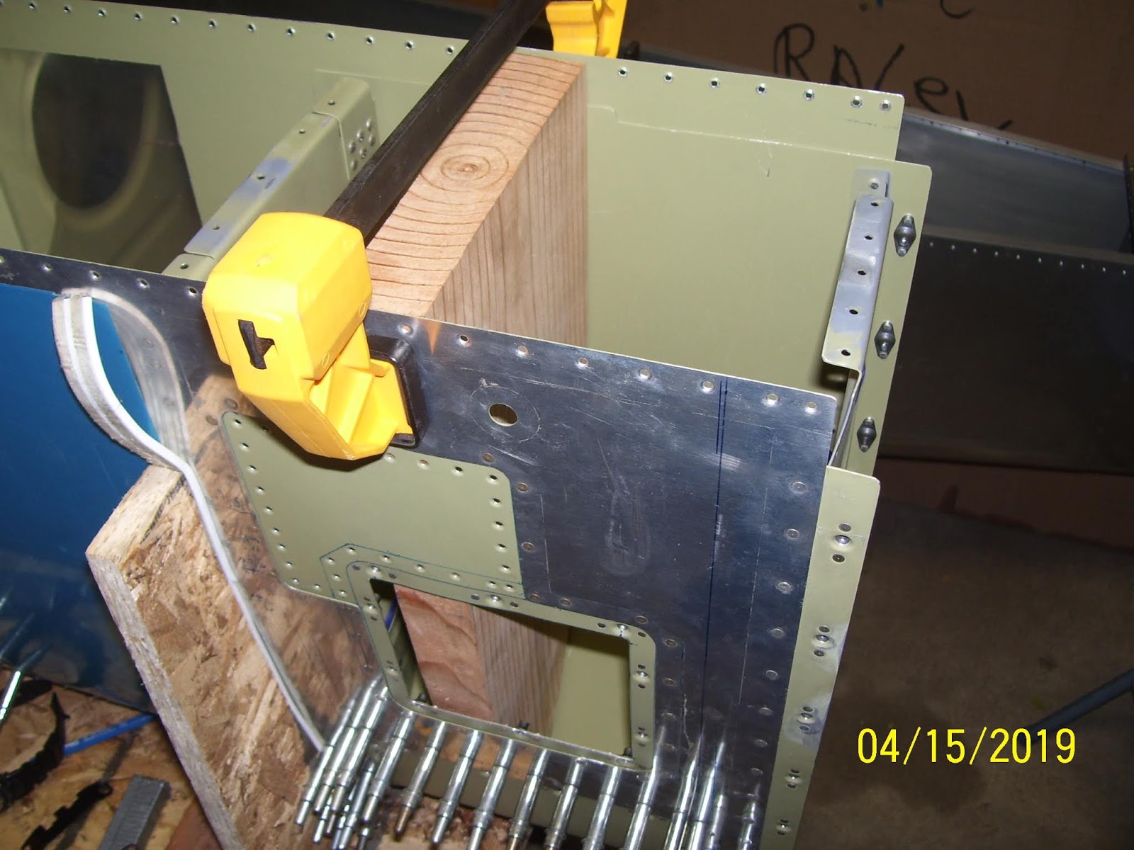
To address this, I came up with an idea. I needed to somehow add some stiffness to that area just as I have had to do at other times. I remembered that I still have several of the form blocks that I used to shape the subskin so many years ago. SO I took one of them and a bar clamp, set it down inside the LE where I thought it would provide sufficient stiffness, and clamped it down just enough to hold it in place. With all the nutplates and shop heads of other rivets it did not sit down inside the skin totally flush, but it was good enough to provide the required stiffness in the areas where I needed to rivet the outer skin to the subskin.

This worked out REALLY well. Even if the outer skin was pressed into the wood a bit awkward due to nutplates being in the way, it was good enough to hold it there temporarily without distorting or bending anything out of whack while I set the rivets. Yet another tip for future builders. 

Here is shot after I was able to use the form block by moving it as necessary to allow room to hold the bucking bar while I set the perimeter rivets around each access hole. These would be the rivets that would normally secure the mounting or backing plate that allows a flange to mount the cover plate onto it with screws. In my case the subskin serves as that mounting plate, but I used the same rivet pattern as called for in each actual mounting plate:
Once these perimeter rivets were set it was time to mount the original cover plate from Vans permanently to the subskin. Here it is clecoed into position for the final time:
And here it is after all the rivets were set:
It still fit just like a glove. I was really pleased with how that went together. I was concerned about some of the edges curling up, but that never happened. It fit just like it was supposed to - to cover up the old Vans hole so I could use the SafeAir access panel hole instead. 

And finally the back side with all the shop heads after this was all done:
Like I said - Swiss Cheese.
 But slowly all the holes are getting filled.  Next steps are to set the cradle on its side and secure the back side of the LE so I can push on the forward tip rivets to set them. The problem is that I still need to be able to reach deep inside with the bucking bar to set those most forward rivets - and these are the most critical to do correctly the first time. I can't afford to have to drill any of those out. So the next session will be spent doing a lot of prep and ensuring that everything is exactly right so that setting these last rivets is as easy s possible.

KPR


Saturday, April 13, 2019

Final Assembly of the Left Wing LE Begins

After evaluating the nutplate situation a bit more I decided that the nut plate is fine for now. I can still replace it later if I want to.

SO the next step was check the instructions again. They basically take you through the entire process to finish the fuel tanks, but because of the mod to the LE I really needed to finish that first. After the tanks are all but finished, the instructions tell you to rivet the LE together with it in the LE cradle. So the reality is that the LE can be assembled while in the cradle at any time. It cannot be riveted to the Wing spar, however, until the fuel tanks are done, because the screw holes in the tank skin that slide over the top of the joiner plate attached to the LE need to be final drilled, deburred, and dimpled for the #8 screws, and the assembly fit-checked with the LE again to make sure everything is AOK. One of the things that also gets in the way of this is excess proseal on the end rib of the fuel tank that may interfere with the joiner plate flange. Sometimes this has to be trimmed away to prevent this interference, which can cause the screw hole alignment to get messed up if this is not resolved. SO this is all interlinked,  but for now I can go ahead and rivet the LE together, shich also means that the subskin is finally going to become a permament part of the LE.

The instructions say to cleco it all together and then "ensure that the rear holes are perfectly aligned with each other, which I guess means the holes on the rear flanges of each LE rib. SO to reverify this I think I clecoed it all to the wing spar one last time to reset all the ribs after tugging and pulling on all that vinyl, then I carefully removed the LE again, making sure that I did not twist or bend it so that the hole alignment would not be disturbed. Then I carefully placed it back in the cradle.

Next, there were some scratches on some of the rear rib flanges and the area of the joiner plate where the tank skin edges dug into the primer and the metal a little bit, so I sanded those areas out to remove the stress risers. Then the instructions say to start with the rear-most rivet hole with a squeezer on the top and bottom of each LE rib to secure them into place. I was able to do this easily with the pneumatic squeezer and a flange yoke. As part of the mod, the two inboard-most LE ribs also have two additional holes that I needed to add to the skin and each rib and the subskin. These "second" to the last rivet holes are relatively close to the rearmost holes, so I thought I could set those rivets with the air squeezer as well. The thing that I forgot was that the #2 inboard rib, which is a modified 408-1 rib, has the shop heads of the AN470 rivets protruding a bit from the rib web, and when I tried to set these with the air squeezer the rivet set hit the edge of those shop heads and caused the set to jump, which resulted in a badly set rivet, which I had to drill out and replace. After drilling out the bad one, I decided that in this situation I needed to use the hand squeezer to maintain positive control of setting the rivet so that I could ensure that both the yoke AND the rivet set would clear the shop heads of those AN470 rivets holding the rear rib flange extensions onto the rib web. I put the 3 inch yoke on the hand sqeezer and got those rivets set as well.

Now that the rear-most rivets were set on the top and bottom sides of each LE rib, it was time to get out the rivet gun and the bucking bar. More decisions to make and prep to do. For example:

I had to decide the pattern I would use to set the rivets on each rib
I had to get towels and place them inside the LE skin to prevent accidental dings in case the bucking bar slips out of my hand
I had to tape up the edges of each rib web to help prevent gouges from the bucking bar if it slides off the rivet shaft
I had to figure out how to clamp down the table/cradle assembly to ensure that NOTHING would move or slip during the riveting process
I had to check the air pressures on the compressor and at the adjustable pressure regulator on the gun with the new slightly heavier rivet set.
I had to determine all the rivet sizes I would need to attach various parts together.

ON the last, the plans call for AN426AD3-3.5 for he main rib flanges, and AN426AD3-4 for the rivets that attach the skin, rib flange, and joiner plate assembly. However, I found that the 3.5s are OK for the main rib flanges on the main ribs, but on the two ribs that are involved with the subskin assembly, I found that the 3-4s were good for the skin-to-subskin rivets with no rib flange involved, but I found that a 3-4.5 was the correct length for the rib flange, subskin, and outer skin assemblies. A 3-4 just is not quite long enough for some reason.

SO the plan was to start on the center ribs and then work outward toward each end rib. I also started on the bottom side of each rib because it is flatter than the top - this is something that many builder advise to do when building the fuel tanks because you can set the tank down on the bottom afterward to make work on the top a bit easier. I worked from the rear-most hole to the front, as stated in the instructions.

When I started, the one thing I forgot to do was check and reset the pressure on the air compressor, which had been tuned down to 75 psi for the air squeezer. Since the pressure on the rivet gun is controlled by  separate regulator attached to the air inlet of the gun, the pressure at the compressor needs to be at 90 psi. Since I forgot to do that, the first several rivets I set seemed to take forever, and the shop head was not being formed as quickly as I was expecting. A quick check and reset of the pressure at the compressor basically fixed that problem.

Time for the pics. Here are some of the new "rubber boot" flush mushroom rivet set showing the before pic, the disassembled pic before trimming down the rubber, and the "after" pic showing the trimmed down rubber on the reassembled tool:
I took the rubber boot and ran it by hand across some aluminum oxide 220 grit sandpaper after marking it with a sharpee line. I did not want to sand too much of it away because it is still supposed to be a little proud of the set to provide some gripping ability on the skin. Then I put the tape on the rivet set - another important little trick to prevent damaging the metal with this pesky tool:
Here are some pics of the tape prep and towel prep to minimize or prevent other possible damage:

And finally some pics of te rivet gun in place and ready to set a rivet, and another pic of the bucking bar, using the angled side of the bar, showing how all this has to be positioned to set each rivet:


And here are some pics showing the progress - basically not more clecoes and a clean looking skin. the reality is that I have several rivets to drill out, mostly because they were overset, but a few are badly set rivets that need to come out. Overall I was pleased with the rivet process, and the rubber mushroom seems to do well at preventing skin damage. But the one thing that it does NOT do is ensure that the set cannot "walk" across the skin. I had numerous events where this set decided to have a mind of its own and start walking up, down, and to either side. Luckily it did not seem to damage the skin at all, thanks to the rubber edges I guess. It is designed to allow it to swivel a small amount so that you can presumably hold the gun not quite perpendicular to the skin and still get a good set. Personally I found that I still had to figure out what angles to use both up and down and side to side and how much pressure to apply to hold the rivet gun in place. 


You will notice that I left the bottom/forward-most rivets for later. These are too low to be bucked - both from a position standpoint of the gun and bucking bar, and a gravity standpoint where the rivet cannot stay in the hole at the curved angles of the these holes - it falls out. SO these will be set with the cradle turned on its side after all other rivets have been set. These forward rivets are the ones I dread the most, because the potential for skin damage due to a slipping rivet gin or bucking bar is extreme, and I already have enough bad experiences with that to prove it. The trick, once again, is securing the work so that it cannot move, and so that you can easily position the gun and the bar to set those rivets. it usually also means that you have to set these "blind", meaning that if you do this solo, you will either be able to view the bucking bar on the rivet, or the rivet gun, but you will not be able to see both at the same time. I hate setting those rivets. Curved surface riveting sucks big time.

Anyway, this was the longest work session I have had on the place for a very long time several hours today. I only have about 3 more ribs and the final forward rivets to go, as well as the swiss cheese rib, subskin, and outer skin assembly for the LE mod, so there are still a large number of rivets to set. Hopefully I will get most, if not all of them done tomorrow.

Pounding rivets again using every method on the planet and lots of tricks you learn along the way - so far so good...….

Sunday, March 31, 2019

Prep for Final Assembly and Riveting of the LEFt wing LE

As mentioned previously, the next step was to remove the vinyl inside the LE skin that I have left on all this time to protect the metal. I do not prime the entire interior surface to try to save some weight. The epoxy primer overspray and cold temps have left this remaining blue vinyl in a state that is very difficult to remove. Here is one of the problem sections that I needed to remove:

I was not able to take my finger nail and lift up the edge to peel it away like I normally can. The primer hardened onto the metal next to the vinyl making this difficult. So what to do? I still need to remove this protective vinyl because if left on it can cause corrosion to occur by trapping moisture and debris between the vinyl and the metal. Unfortunately the vinyl only chips away and it won't peel off as one piece. 

After pondering this for a bit I remembered that I have a heat gun around here somewhere. I thought that maybe I can use that to heat up the glue on the back of the vinyl to at least soften it up a bit and see if that would allow it to separate from the metal easier. So I got this bad boy out and gave it a whirl:
After mucking with the setting son the gun and experimenting with how hot things could get, I finally came up with a procedure that involved holding the gun at a safe enough distance and heating up the entire surface of the vinyl as well as the edges until the vinyl softened up enough for me to peel it away. What I found out real quick is just how fast and how hot that heat gun can heat of the vinyl AND the metal. SO after figuring out how not to burn myself too much, this actually started to work pretty well:
Here is the sheet removed from the inside of the LE skin:
And here are some shots of what happens to some of the remnant primer 

It separates from the vinyl and rolls up into little flakes that have either a positive or negative charge that causes them to stick to the LE skin. After I got all the vinyl sections in between the ribs removed I had to use a shop vac to remove all the primer flakes.

The next task was to remove the red ink with the metal specification information. Normally isopropyl alcohol removes this very easily, but it has been baked on for so long that t was no longer doing a very good job, so I switched to using acetone, which worked very well. I was not too worried about wiping the acetone on some of the epoxy primer because that stuff, once hardened, is almost impervious to anything, and is very hard to remove with anything but acetone rubbed very deep and hard into the primer to soften it. What little acetone did come into contact with the primer evaporated away before it did any harm to the primer. I used paper towels and small dab of acetone to remove the red ink on the metal. Why remove this? Well some say it can lead to corrosion over time as well, but others say it doesn't harm anything. UP to now I have always removed it from the metal as part of the final assembly prep, so I did it here as well.

Once this was all done, it was time to final assemble the LE for what I hope will be the last time. the subskin and two inboard ribs were re-clecoed to the LE skin again, and the entire LE was placed back on the wing spar due to one thing I read in the instructions about making absolutely sure that the rear edges of each LE rib were exactly straight. The only way I knew how to ensure that was to re-cleco the LE back onto the wing spar again so that all the rear rib flanges were in alignment with the spar web, and then I can remove it again and start riveting the entore LE together. 

I also needed to put it back on the wing spar because I wanted to screw down the new removeable section using those new nutplates I just riveted to the subskin, so that I could check the actual "installed" fit of everything. As with everything else, I found out that after I screwed down the removeable section, all of ONE of my screws sat nice and flush to the skin exactly as planned. One of the screws was not laying flat on once end, suggesting that either my screw dimple or the hole or the nut plate was not properly oriented for the screw. It is not so bad that I feel that absolutely must fix it, but it may end up bugging me enough to the point where I am going to fix it anyway. This means removal of the subskin again to reset another nut plate, and of course it is one of the corner nut plate that are difficult to set.

I may actually try to set the new plate with everything mounted on the wing, but I am still debating that with my self. Here is the string of pics showing the part as originally envisioned, planned, and realized:

And finally, the same non-matching fit that I have been dealing with shows up once again after the part is screwed down onto the subskin, but the inboard side is quite flush and looks really good. I think I can still flush out the other side with the LE by applying a little fiberglass magic later on. 
Overall I am happy that it seems to have gone together pretty much how I envisioned it. Here are some final shots of the screws through the nutplates on the inside of the subskin:


Thursday, March 28, 2019

More Nutplate Hell and Creative Clamping

After several days I was finally able to finish riveting all 20 nutplates to the subskin. Man did that turn into a royal pain in the ass. As of the previous post I had made it to the last side and had messed up the rivets on the last, most-forward nutplate along the edge. This is where the skin starts to curve at the very front, which makes trying to set straight rivets with a rivet squeezer a bit of a challenge. I think I managed to finally get it after drilling bad rivets out a couple of times.

With the side nutplates installed, it was now time to tackle the hard part - the remaining rear-most nutplates on the top and bottom sides of the subskin. I could not use a rivet squeezer on these because they are too deep into the center section of the subskin for any of my squeezer yokes to reach. SO that meant that it was time get out the rivet gun and the bucking bar - something that I have not done for a very, very long time.

I decided I did not think I needed to practice on anything, because I was able to get the air pressure setting correct for the rivet gun. Looking back I wish I would have been more experienced about that when I riveted the horizontal stabilizer skins onto the frame. It hangs up on the wall in my garage so that every time I walk in I have to look at it, and I cringe every time that I do. That is because I literally beat the shit out those skins because my pressure was too high, and almost every rivet attaching the skin to the forward spars has this large skin dimple from over hammering the rivet gun on the skin. By the time I got to the elevators I had pretty much figured that out, but I literally pounded the HS skins almost to death..

Anyway, with the air pressure set on the gun, the next step was to figure out how to clamp everything down tight. I ended up deciding that using my bench vise should allow me to set everything up to use both hands to buck these rivets without needing to worry about securing or holding the part. Here are some pics if what I came up with. IT involved the bench vise, a small 2x4 for the smooth front side of the skin, and a custom sized much smaller piece of 3/4 inch plywood for the back side. All of this had to be positioned very carefully to ensure that there was enough space for the rivet gun and bucking bar, and to allow everything to be clamped tightly down without deforming any dimples in the skin. With so many dimpled rivet holes in this custom part, this became a challenge at times.

The top part of the skin was easier because there were not as many holes to dodge while clamping it all down:
I used a bar clamp to provide stiffness and resistance on the top part of the skin. This was the difficult part of trying to use the bench vise for this large piece of aluminum. The vise only provides a small amount of depth, so the top part of the skin remains very flimsy unless it reinforced with something such as the wood that I used.

On the front side I had to make sure there was enough room for the rivet gun:

And here is shot of the back showing how I had to be careful about the size of he wood  used and how it was positioned to avoid smashing or deforming any existing dimples. The other concern was of course making sure that I had enough room to use the bucking bar. This did not prove to be much of a problem until I got to the corners where the first side nutplate is located relatively close to the rear-edge nut plate in the corner. 
And here is yet another creative clamping method where I was able to use the access plate hole on the bottom side to insert another bar clamp for added stiffness. 

The stiffness is needed because, regardless of who you may talk to or what you may read in a book, you HAVE TO apply some pressure on the rivet gun and the skin to ensure that it will NOT bounce when the rivet gun is activated. This is what directly causes badly set manufactured rivet heads where they sit noticeably proud of the dimple because the underlying skin was allowed to flex and bend each time the rivet set was pounding against the skin. The part needs to be clamped in such a way that any movement of the part is severely restricted. This is the only way that you are able to buck good quality rivets. Sometimes the temptation is such that you do not take the necessary steps to ensure that everything is properly clamped. Then you basically pay the price for the mistake, and you have to drill out bad rivets and try again.

I was able to get all of the nutplates riveted in place, except of course for the very last one, which was a corner nut plate on the bottom side of the subskin. This one proved to be so difficult that I think I drilled the rivets at least 4 times and replaced the nutplate once because it was deformed beyond acceptable limits on one side or the other. I think I must have drilled out no less than a dozen rivets and replaced 3 nutplates during this whole exercise. The top side ones went pretty well, but the bottom side was another story. In fact, I had screwed up the rivets on the last nut plate so many times that the shape and condition of the dimples in the subskin. it was so bad that I was now unable to secure the nutplate in place with a cleco so that the flange on the nutplate would sit flush against the skin. I had to start using tape to hold it in place. When this did not even work, I had to take out my other arsenal of tools. Luckily I was able to use my 4 inch no hole yoke on the bad nutplate on the bottom of the skin. I mounted it on the hand squeezer because I was not having any luck with the gun and bucking bar, and the pneumatic squeezer was too bulky to fit as well. 

So my only choice was to use the hand squeezer so that I could position it and take my time to set the first rivet to make certain I did it correctly. I was able to set the first rivet on one flange just enough to hold it in place where I could then finish it up with the gun and bucking bar. The manufactured head of the rivet ended up sitting just proud of the skin on one side, but I had a plan for addressing that. Part of the plan was to try to use the rivet gun to move it a bit more flush to the skin - this only partially worked.

With the first rivet set as well as could be expected, I then was able to properly set the second rivet with the rivet gun and bucking bar. The corner rivets only allowed just enough room to insert my small tungsten bar in between the two nutplate flanges on the corner. One slip and the rivet, skin, and nutplate would be history. In fact, he bar did slip one time and slightly creased the skin, but I deemed it as OK since it was a dull crease with no apparent stress risers, which means I just barely stopped the rivet gun in time. Had I not done so this entire subskin and the planned project would have come to a screeching halt.

Here re the pics of the finished nutplate rivets on the ear side of the skin. First the nicely set ones on the top side:
And then the less-nicely set ones on the bottom side. Some of the primer was knocked away from all the repeated pounding from multiple attempts to set the rivets, and if you double click on the pic you can see it in more detail and tell very easily which rivets caused me the most trouble. 

And here is the back side of the nutplates all riveted together.

Now, remember that slightly proud rivet I mentioned earlier? Well, here was my solution for that. A long time ago I was at Harbor Freight, an I just happened to stumble on this next little gem - a watchmakers hammer. I used the round headed side of this hammer to lightly tap on the edge of the rivet that was sitting proud, and I was able to get it to sit much more flush after just a few taps with this hammer. This hammer was critical for this because the small size and weight of the ball end of this hammer was just about perfect for ensuring that it only contacts the surface of the rivet head and not the surrounding skin. If it was too large it would dent the surrounding skin, but I found this little hammer to work exactly as I thought it would:
And finally, here is just a small sampling of all the tools  ended up using to accomplish this seemingly small task. As I said before, most of this was pleasant to work on, but those few times when things got difficult, they got VERY difficult. I could not risk damaging or screwing up the subskin because it has required so much customization that there was no way at all that I would be able to take the time to try to fabricate a new one, nor would I even want to. If that part were to be compromised beyond use or repair, I would abandon the entire modification and return to a stock LE without even looking back. Too much time and too many delays with this to even think about starting it all over again.
And here is he pile of drilled out rivets and damaged nut plates that I had to drill out and replace, sometimes repeatedly:
So yeah, I got really good at drilling out AN426 rivets again, too. Anyway, I was able to pound some rivets again, so that is always good. And, more importantly, that step is now complete, which allows me to move on to the next step. 

So next up s to remove all the remaining internal sections of vinyl covering on the inside of the LE skin that I have left in place all this time. Unfortunately this is proving to be difficult, because some of he overspray from the epoxy primer that I used has hardened the vinyl in those areas, and as a result is very difficult to pry up a corner of the vinyl and keep it going so that I can remove the entire thing without it breaking apart. That vinyl has also been stuck to the skin since 2010 when I ordered the wing kit, and I already know that the longer it stays on the glue makes it harder to remove as it gets older.

After that vinyl gets removed it is finally time to rivet the left wing LE together. Great  - more curved surfaces t deal with. I can hardly wait...….

KPR

Tuesday, March 19, 2019

Started Riveting the Nutplates for Securing the LE Removeable Section to the Subskin

I started out by free-handing the attach rivets for the first couple of edge nutplates on the subskin with the pneumatic squeezer, but even though I was able to set these OK, I did not like the risk and the inability to hold that beast of a heavy squeezer with only one hand while holding the subskin in the other. So before I set any more rivets, I had to rig up another custom method of clamping the subskin to allow the proper support and positioning of the part for riveting the nutplates on. Here is the initial setup using my padded 4x4 wood blocks (3 of them) and the bar clamps similar to what I have done before:
I had to reposition and reclamp the part for each new rivet, sliding the subskin as close as I could get it to the clamped blocks without causing interference between the squeezer and the clamps. I also added a second clamp on the other side to tighten up the structure. This allowed me to use both hands on the squeezer to set the rivets.

I used my 3 inch yoke which had enough clearance from the edge of the subskin to set all of the edge rivets on both sides. The 4 remaining nutplates on the rear edge of the top and bottom of the subskin will have to be bucked - oh boy - there is something I have not done in a while. 
Also shown in the above pic are the flat rivet sets that I used. The thing I hate about nut plates is that the rivets that attach them are on either side of the center shaft for the screw. This does not leave very much room for positioning the rivet sets so as to be centered over the rivet shaft without being too far over to one side to ram into the screw thread shaft, thus destroying the nutplate. ON the other side of the nut plate exists the possibility that you could slide too far away from center, causing an incorrectly set shop head on the rivet. IN order to avoid hitting the screw shaft, I needed to use a 3/8 inch wide flat set (on the top of the yoke in the above pic), and the 1/2 inch wide flat set on the bottom which goes over the manufactured head of the rivet. This means that the squeezer must be positioned as centered as possible to avoid either condition described above.  And may I say that it is a royal pain in the ass having to use a flat set that is that small to do all the mashing of the shop head. 

Lets just say that so far I have had to drill out about 4 rivets because of this, and I may have to replace one nutplate after damaging the edge of it when the squeezer slipped while squeezing, to the point that I am not happy with it. The other thing that sucks about this session is that I cannot position the squeezer very easily in such a way that I am able to pull against the manufactured head with the top of the yoke, so that the ram that moves from the bottom does not displace the part or cause the squeezer to slip out of position as it travels upward. Instead I have to keep the extremely large squeezer body on the outside of the part, which forces me to do the opposite by placing the moving ram on the manufactured head of the rivet instead of the shop head. The result so far is 4 badly set rivets that needed to be drilled out and replaced. 

The good news is that I was able to set almost all of the edge nutplate rivets on both sides of the subskin using the pneumatic squeezer. And the rivet heads seem to be pretty flush on the subskin surface where the removeable section will be sitting on top of them, so I was happy about that as well. Here is the result of one side of the edge nut plates installed:
I should also mention that I used my rivet gage to determine the size of the rivet that I needed - the winner was AN426AD3-4 rivets, These set very nicely in the dimpled nutplate flanges and left more than enough of a correctly sized shop head. 
You can tell that I have riveted anything in a while, because I also forgot one other cardinal rule that I had established long ago when using the pneumatic squeezer to set the rivets. The instructions for this tool say to set it to 90 psi, but  found that this tool has just too much force at that setting, and this can cause the tool to shift out of position or ram with such force that it almost damages the part. So I found long ago that setting the air pressure to 75 psi works a lot better. It does not activate as violently as it does at 90 psi, and it still maintains enough force at that settings to more than adequately set AN426 rivets.  Here is a shot of the air pressure setting for posterity later on.
Another shot of all the clamps in position
And finally a shot of a successfully set nut plate using this setup. I made it all the way to the last rivet on the last edge nutplate and managed to screw that up because I got too fatigued and wanted to finish it. So I drilled that one out and will reassess that one tomorrow. Then I will need to come up with yet another custom clamping setup so that I can buck the remaining rivets on the remaining nutplates  When that is done, the subskin goes back into the LE skin for the final time, where all those millions of dimples will also be riveted together into a solid LE with all the custom work completed.