
Been a while since I last posted. Snowblower repairs, bad weather, and a wonderful cold have kept me at bay for a while on the project. Finishing the scarf joint turned out to be royal pain in the butt. I thought I had finished the joint, had a pretty good fit between the wing skin edges and the fuel tank skin edge, and then I final sanded everything with 320 grit aluminum oxide sand paper to remove the deep scratches. Then I took both wing skins off of the frame set all the remaining dimples with my squeezer, masked off the sanded areas of the wing skins where I formed the scarf joint, and primed them all with NAPA 7220 self etching primer.
Then I reapplied both wing skins to the frame to check the fit, since this was the first time that the dimples were added to that entire area. To my utter disappointment, the skins looked like they had not even been touched. The edges stuck out like sore thumb. My friend Mike had warned me about this a while back, but I thought that was because of the skin edges not being slightly bent, which I had already addressed. However, it became apparent real fast that the newly dimpled skins and the added primer were both causing the skins not to ft very well against the wing spar flange.
SO I called Vans about this. they said that you really can't judge how they will go together until you actually rivet them to the spar, and not to worry about it too much. Well, I decided to try to alleviate at least some of this ill-fitting issue, so I took off the inner skin, noticed that the edges of the skin were quite thin, but that the rest of the metal moving away from the edges still seemed to be a bit thick - indicating that I had not removed enough metal on the inner portions of the wing skin. So out came the file one more time. This time I focused ONLY on the inner portion of the skin, staying away from the edges as much as possible.
Then I re-sanded the deep scratches from the file and re-primed the small 1 inch square area that I was working on. Then I rechecked the fit and decided that enough was enough, and it was time to move on. I think I pretty much realized at that point that it was the dimples and how they were fitting into the countersunk hole of the spar flange, that as causing the fit problem, even though the hole has been countersunk a little bit more than flush per Van's instructions.
When this areas gets riveted to the spar that metal will be forced into the spar flange hole and hopefully will smash down a bit more with the force from the rivet gun. If I don't like the fit after that, I can drill the rivets out and figure something else out. OH - but wait - by the time you get to this joint in the wing for riveting, you have already done the rest of the holes in the skin, because per the plans you save this lovely area for last. So I'll be damned if I am going to rivet everything else just to find that this area is still not seating properly. Others don't seem to have problems with any of this, so why the hell am I?
Time to move on. The scarf joint is as done as it is going to get. I am pretty certain that all that I will get for my efforts on this is a cracking wing skin in this very area once I start flying. If I do, you can bet that I will be asking myself why I even bothered with this stupid scarf joint - which some builders have also decided not to do, since it is "only cosmetic" per Vans.
I re-inspected the state of the leading edge assembly after my near disastrous and stupid attempt to force it off of the wing spar with the fuel tank mounted next to it. (See my Stupidity label to find the post). I tweaked the rear flange of the inboard 408 rib a bit more with the handseamer, and I checked for cracks or fatigue, and did not see any evidence of that. I removed the fuel tank assembly from the wing spar and remounted the LE assembly, all the while having flashbacks to my stupidity from before. I re-secured the LE assembly to the wing spar with clecoes and then added the fuel tank assembly. That's when I got my next head scratching moment - when the edge of the fuel tank skin and the LE skin did not line up correctly.
Initially I had a situation where there was no gap at the very tip of the LE and the fuel tank skins, but as you went further aft, this turned into at least a 3/64s inch gap. WOW! I thought I had everything here all matched up nice and neat - so once again I foud myself asking what the ^&*O&%$^! Obviously this was some sort of angular issue between the wing frame and the LE and Fuel tank assemblies, which I had verified long ago were butting up to each other with no gap whatsoever - so I knew that something just "wasn't right."
So I'll cut to the chase. There were two things that found that I needed to do. The first is a long standing problem that I have had ever since I put the frames on the wing stands. I used a hydraulic jack to support the center of the wing frame, which does sag under the weight of the wing assembly when mounted on the stands at both ends. I thought that this would be a great method - but found out long ago that these jacks do NOT hold their pressure forever, and they start to slip. As a result, I have had to continuously reapply pressure to the jack to lift the center section to keep everything aligned.
This time I wanted to be sure to recheck the "level" state of the frame by using a fish line strung across the rivet holes of the spar flange and held in place by two clecoes - one at each end. Then you apply the pressure from the jack until the fish line cuts through all the rivet holes evenly. Works great, and I found that I needed to apply more pressure once again to level everything out. The only problem with this is that to do it correctly you need to remove the wing skins from the frame. I did all this in warm weather, before the cold snap hit over the past couple of days. Seemed to level everything out again.
Today is the first day since I got sick that I have been able to go out and check on things in the garage. What I found this time was even more shocking. This time the gap between the LE and fuel tank skins was consistent from top to bottom, and was quite large on both sides. So once again I am asking what the ^&%^%#%$!. I rechecked the jack, but after leveling the center again I still had this huge gap.
The Le had been firmly reattached to the wing spar several days ago, so it was not moving. That meant that something was up with the fuel tank for some reason. When I put both assemblies back on the wing spar, the fuel tank was butted up against the LE skin and then I clecoed the inboard-most holes in the baffle and Z bracket on that end. Then I put #30 clecoes back in each screw hole through the nut plates, just as I had done many times before. None of the other fuel tank ribs, including the outboard-most rib, were clecoed, because at the time I did not think I had access to those holes since the LE an fuel tank are now butted up against each other.
So while scratching my head about this latest quandary, I came up with a plan, based on the only thing I could think of that was causing this gap problem - the clecoes I used to attach the fuel tank assembly to the spar were not allowing the skins to line up correctly for some weird reason. So I came up with a brilliant idea - make absolutely sure that the center of the wing frame was level (again), remove all the fuel tank attach clecoes, slide the fuel tank assembly over till the skins are snugged up against each other, and re-clecoe the fuel tank to the spar again. Then check the fit and go from there. I was skeptical about this whole thing, because I thought that the rib to Z bracket holes would now be out of alignment after sliding the skins together to "make" them fit. I found myself asking - "did I really mess up the whole fitting process and drilled the wrong holes in the wrong places, and that is what is causing all this?" Could I really be that stupid - again?
However, much to my surprise, after I re-clecoed the inboard rib to the inboard Z bracket, and then started carefully applying #30 clecoes to the screw holes through the nut plates again, the skins magically all lined up like they were supposed to, and they stayed that way as I added each cleco. Thank goodness for that is all I can say. Then I saw that I could still apply the clecoes to the outboard fuel tank rib and Z bracket through the access panel opening of the LE. And the skins stayed flush together after I did that. How bazaar is that!
The only thing that I can conclude from this is that I think there was some misalignment of the inboard and outboard ribs when the rest of the fuel tank assembly was removed to match drill the baffle to Z bracket holes for the remaining fuel tank ribs. It could also be that the sagging center section of the frame, combined with some slight shifting of the screw hole clecoes, may have caused the misalignment occur. Putting #30 clecoes in the holes intended for the screws in the fuel tank skin, which have yet to be dimpled, is a bit out of the ordinary. Normally you put clecoes through matching holes in two or more pieces of metal.
However, in this case, until the fuel tank skin holes are final drilled to size for a #8 screw, and dimpled, you are inserting a clecoe into a hole in a flat skin, and then in turn the rest of the cleco must extend further than normal, all the way into the end of the nut plate on the inside of the spar flange. This results in a clecoe that is under higher spring tension than usual, since it has to be extended more than usual, and the flat skins are then being pulled slightly into the large countersunk hole in the wing spar flange, causing some uneven tension on the fuel tanks skin. When you combine all this with an unsupported center section of the wing frame, it is not hard to see how things might not line up correctly.
The lesson learned from this is to make sure that parts that you know are supposed to fit together are actually mated that way first, and THEN you cleco everything in place - NOT the other way around - i.e. clecoe everything and then check the fit. Clecoes that are inserted into places where they may be allowed to shift or distort the assembly a little (flat skin screw holes into countersunk holes nut plates for example), can cause such a mis-alignment of closely fitting parts like skins. The second lesson learned here is that I need to replace the STUPID hydraulic jacks with a 3/8 inch threaded shaft with a small wood support on one end, and a large washer and nut assembly on the other end, inserted into a solid wood base with a hole slightly larger than 3/8 inches for the rod to freely insert into, and adjusted so that the center section of the frame remains level ALL THE TIME! Don't use stupid hydraulic jacks unless you want to feel my pain.
So I already have one screw jack assembly from another builder, which I obviously never used, and I'll need to fabricate another one for the other wing stand. That is my mission for tomorrow. SO in short I have been on a bit of wild ride ever since the time came to remove the LE from the frame to start working on the fuel tank assembly on the wing spar. It's been one wild thing after another ever since.
The last thing for tonight is that I finally have the LE back on the wing frame, which is the point that I was trying to get back to ever since this latest round of madness began. I needed to get the LE back on the frame one last time for it is final-assembled so that I can get down to business and make those final decisions about cut lines and new rivet holes and locations for nut plate and screw holes, all in preparation for the big "cut your LE to pieces" exercise. I worked out some final measurements tonight and will elaborate more on all that in my next post. I am very close to being ready to make the cut in the LE skin once these measurements are finalized.
Showing posts with label Scarfing. Show all posts
Showing posts with label Scarfing. Show all posts
Wednesday, November 8, 2017

Monday, October 30, 2017
Got some stuff from Vans
Not too much to report this time. I received an order that I placed for some stuff from Vans, including the necessary LP-4-3 and 4-4 pop rivets that I plan to use for the majority of the Leading rivets that attach the rear flange of the LE ribs to the wing spar. I also ordered several #6 ring terminals and several feet of #18 wire so that I could practice crimping with my crimping tool, which I have not done since I took the Sport Air electrical class a long long time ago.
I needed to do this because the capacitive fuel sender kit requires you to put ring terminals on several pieces of wire that will be inside the fuel tank and screwed to each metal plate, and then to a BNC connector at the wing root that will connect to the other wire and connector coming from the fuel gauges and converter units in the fuselage. So I watched multiple videos from EAA and from SteinAir, and practiced crimping several terminals. I think they came out OK but I'm still not 100% satisfied with some of them. Continuity and resistance checks are all good, but some of the crimps don't look the way I think they should. Some combo the amount of stripped insulation and where I am placing the sleeve in the crimper I think.
I also ordered a small amount of Proseal just so I could play with that a little before I am ready to do the big job on the actual fuel tanks. I also ordered some rubber grommets that turned out to fit my .75 inch holes that I drilled in each wing rib for the black conduit to run my wires through. The problem is that the grommets only have a 1/4 inch opening in the middle, and I may want a bit more than that. At any rate, it was nice to have some to see how they install. I'm sure I'll have places where they will come in handy.
Some of the other stuff I ordered was the metal reinforcement kit for the horizontal stabilizer center section of the front spar, which was found to be prone to cracking in certain areas. I'll be installing this after I finish the wings while I wait for the fuselage so I can get it done. I may even decide to replace one or both of my stab skins, since that was the beginning of several "first time" blunders when trying to rivet my very first large skin.
I also ordered electronic copies of my RV-8 plans and instructions-something that Vans had made available for a while now but I never acquired. It makes it so much easier to to review everything without carrying around the big notebook.
Other than that, I managed to get outside tonight and final sand and clean the scuffed an filed areas of the skins for the scarf joint. Hopefully in the next day or two I will prime those areas and dimple the holes that still need to be dimpled, and then finally I can move on to bigger things with the LE again.
KPR
I needed to do this because the capacitive fuel sender kit requires you to put ring terminals on several pieces of wire that will be inside the fuel tank and screwed to each metal plate, and then to a BNC connector at the wing root that will connect to the other wire and connector coming from the fuel gauges and converter units in the fuselage. So I watched multiple videos from EAA and from SteinAir, and practiced crimping several terminals. I think they came out OK but I'm still not 100% satisfied with some of them. Continuity and resistance checks are all good, but some of the crimps don't look the way I think they should. Some combo the amount of stripped insulation and where I am placing the sleeve in the crimper I think.
I also ordered a small amount of Proseal just so I could play with that a little before I am ready to do the big job on the actual fuel tanks. I also ordered some rubber grommets that turned out to fit my .75 inch holes that I drilled in each wing rib for the black conduit to run my wires through. The problem is that the grommets only have a 1/4 inch opening in the middle, and I may want a bit more than that. At any rate, it was nice to have some to see how they install. I'm sure I'll have places where they will come in handy.
Some of the other stuff I ordered was the metal reinforcement kit for the horizontal stabilizer center section of the front spar, which was found to be prone to cracking in certain areas. I'll be installing this after I finish the wings while I wait for the fuselage so I can get it done. I may even decide to replace one or both of my stab skins, since that was the beginning of several "first time" blunders when trying to rivet my very first large skin.
I also ordered electronic copies of my RV-8 plans and instructions-something that Vans had made available for a while now but I never acquired. It makes it so much easier to to review everything without carrying around the big notebook.
Other than that, I managed to get outside tonight and final sand and clean the scuffed an filed areas of the skins for the scarf joint. Hopefully in the next day or two I will prime those areas and dimple the holes that still need to be dimpled, and then finally I can move on to bigger things with the LE again.
KPR
Tuesday, October 24, 2017
Scarfing the wing skins - more info
Wow. It's been a week and a half since my last post. In that time there has been a winter storm, large tree branches falling off the trees that threaten the roof of the house, severe winds, cold temps, and a lot of other things that I had to get done to meet other obligations that had nothing to do with work or with building the plane. I was way too over-extended last week, and I finally got a chance to recover a bit on Sunday. I was pretty much running on empty all last week.
I had to finish editing a video that I produced for my EAA chapter with footage that I shot at Oshkosh when B-29s FIFI and DOC flew together, making this the first time in 50 years that more than one flying B-29 flew in formation with other B-29s. Turned out pretty good - but as always video editing-doing it properly anyway - is an awful lot of work.
Then I promised to do a presentation for the meeting as well - so I had a double whammy for last Friday.
I finally had some time this evening to get back to the scarf joint. In between the last post and this one, I did some more research on VAF about this whole scarfing process. Turns out that, as usual, I should have done the research BEFORE I started the process when I mistakenly thought I had it all figured out.
NEWS FLASH for builders trying to scarf this joint with power tools. DON'T DO IT! I found a 3 page post on VAF with folks basically asking the same questions that I was. The basic advice was NOT to use power tools, as there is a risk of a sanding disc grabbing the skin and sliding away from the desired work area. TOO LATE FOR ME! I already did this on the outer surface of my inboard wing skin, you know - the part that everybody looks at on the top of the wing when your airplane sits on the ground. I took off too much metal over too wide an area. Now I am going to have to have an ugly primer patch on that section of the inboard skin. So, it's not too big of a deal since I plan to paint the plane anyway. But had I wanted to polish my airplane, this skin would probably need to be replaced.
So once again I have proven that for every step that I take where I do something that I have never done before, I manage to screw something up at least once. So my advice to anyone following this blog is frankly to follow somebody else's (Venting). Anyway, following the advice on this VAF post that I found, I drew lines on the inner and outer section of the skin where the joints overlap so that I would know what the borders are supposed to be. Then I took some electrical tape and placed it along side the marks to provide a sort of protective barrier for the next step.
Then you take a standard tooth vixen file and start tapering the skins using the hand held file - and NOT a power tool. Here is pretty good shot of what things looked like before I started to remove more material with the file:
 While this is hard to see, the fuel tank skin is on top, and the inner and outer top wing skins are on the bottom half of this pic. There is no longer a large triangular gap where the outer skin rides over the top of the inner skin, so that is progress. However, there is just enough of a ridge sticking up a bit higher than the fuel tanks skin edge, so it still needs more work. I was quite discouraged to read that some builders had managed to complete this whole task in about 15 minutes. Sucks to be me I guess.
Here is shot that shows the damage that a runaway sanding disk can do, as well as the sharpee line that I drew on one side of the skin. So I am overextended with my skin removal by about another 1.25 inches or so. I drew another line from the bottom side of the wing on bottom of the outer skin so that this line would also be present on the other skin when I separated them again.
 And here is the tape applied along each line on both skins
 Then you take the file and start systematically taking even amounts of metal off by running it across the area of the scarf joint on both skins

 You need to keep slightly angling the file so that it takes more material off at the upper corner of each skin, and thickens up the further away from the corner that you are. My original plan included using a small scotch brite wheel on my drill, but I used it for the wrong purpose. My plan was to use it to remove fine amounts of material, just like it does when you use it to debur the edges on various sheet metal parts. However, for this task, it does not do so well, because the wheel gets gunked up with aluminum as you run it over the flat skin. It is not meant for removing large quantities of aluminum across large flat surfaces. So after I tried this on both skins, I could see where it left some peaks and valleys in the surface of each skin.
Using the straight file allows you to remove an exact amount of material much more controlled and precise than sanding by hand or using a power tool, and you can do it a little at a time and repeatedly check your work as often as you wish. In my case, using the file allowed me to knock down the peaks and even the valleys out so that the skins would lay flat against each other when clecoed together. Here is shot after I filed some more material away on both skins:
 So this was looking better, but there was still a pretty good ridge between the tank skin edge and the wing skins that you can feel when your finger nail runs down along the tank skin toward the edges of the top wing skins. At this point I was satisfied with the fit from using the file. But now it was time to start smoothing out the scratches, and doing some final material removal by switching to smaller grit aluminum oxide sand paper. The sanding disk that I used was 180 grit (quite coarse). Next I used some 220 grit sandpaper to take out the larger scratches from the disk and the file. I also had to smooth out the areas where the disk ran away from me a little. These are the areas where primer will unfortunately be visible on the upper surface of the wing, but it has to be done.
I took a couple more shots after sanding, but they came out really blurry, so I'll have to take some more tomorrow. The end result after sanding was encouraging. The rise in the skin is almost gone. I got tired of re-clecoeing every single bay of the wing skins each time I wanted to check the fit, so as I got closer to the finished edge that I wanted, I ran clecoes along each bay, closest to the overlap joint, to secure the wing skin edges against the wing spar flange. Then I clecoed the overlapping skins together, and checked the fit.This seemed to work pretty well without having to re-cleco ALL of the ribs and skin holes on the more outer and inner sections of each skin.
The current state of the joint is that it is almost flush with the tank skin. I still have about 2 more stages of sanding to do. Most builders recommend final sanding of the scarf joint area with 600 Alum Oxide sand paper.I am going to start with 320 sand paper first, then clean with acetone very thoroughly, and then finish with 600 grit paper, and finally some primer.
Here is a parting pic of my hands full of aluminum dust after sanding the skins with 220 grit paper:
 I decided that I am going to leave a small ridge on the skins for now. When the time comes for paint, There will be a lot of additional prep that will involve sanding, filling, priming, and sealing. This finishing process should being the edges flush with each other, so I am happy with where the joint is at right now. I also do not want to remove any more metal, because I pretty much messed up the whole "scarfing" process, and managed to remove a hell of a lot more skin than I should have. So now I get to worry about the skin being too thin in this area, and being prone to cracking later on as the wing flexes in this area during flight. FANTASTIC!
Anyway, the joint looks a heck of a lot better than when I started. When I do the right wing skins and the bottom skins on the left wing I will exclusively use the file from now on, and I will pay close attention to keeping the scarf joint within the confines of the overlapped section of each skin.
I do still like the decision I made to make the joint with the skins and the fuel tank still attached to the frame, since Vans implies that you do this step with the skins off the wing, and they certainly do not have you check the fit with the fuel tank in their crappy instructions. As I said before I started this step, how in the hell are you supposed to verify that the fit is correct if you don't check it against the fuel tank skin? But I digress - again.
All for now.
KPR
I had to finish editing a video that I produced for my EAA chapter with footage that I shot at Oshkosh when B-29s FIFI and DOC flew together, making this the first time in 50 years that more than one flying B-29 flew in formation with other B-29s. Turned out pretty good - but as always video editing-doing it properly anyway - is an awful lot of work.
Then I promised to do a presentation for the meeting as well - so I had a double whammy for last Friday.
I finally had some time this evening to get back to the scarf joint. In between the last post and this one, I did some more research on VAF about this whole scarfing process. Turns out that, as usual, I should have done the research BEFORE I started the process when I mistakenly thought I had it all figured out.
NEWS FLASH for builders trying to scarf this joint with power tools. DON'T DO IT! I found a 3 page post on VAF with folks basically asking the same questions that I was. The basic advice was NOT to use power tools, as there is a risk of a sanding disc grabbing the skin and sliding away from the desired work area. TOO LATE FOR ME! I already did this on the outer surface of my inboard wing skin, you know - the part that everybody looks at on the top of the wing when your airplane sits on the ground. I took off too much metal over too wide an area. Now I am going to have to have an ugly primer patch on that section of the inboard skin. So, it's not too big of a deal since I plan to paint the plane anyway. But had I wanted to polish my airplane, this skin would probably need to be replaced.
So once again I have proven that for every step that I take where I do something that I have never done before, I manage to screw something up at least once. So my advice to anyone following this blog is frankly to follow somebody else's (Venting). Anyway, following the advice on this VAF post that I found, I drew lines on the inner and outer section of the skin where the joints overlap so that I would know what the borders are supposed to be. Then I took some electrical tape and placed it along side the marks to provide a sort of protective barrier for the next step.
Then you take a standard tooth vixen file and start tapering the skins using the hand held file - and NOT a power tool. Here is pretty good shot of what things looked like before I started to remove more material with the file:

Here is shot that shows the damage that a runaway sanding disk can do, as well as the sharpee line that I drew on one side of the skin. So I am overextended with my skin removal by about another 1.25 inches or so. I drew another line from the bottom side of the wing on bottom of the outer skin so that this line would also be present on the other skin when I separated them again.


Using the straight file allows you to remove an exact amount of material much more controlled and precise than sanding by hand or using a power tool, and you can do it a little at a time and repeatedly check your work as often as you wish. In my case, using the file allowed me to knock down the peaks and even the valleys out so that the skins would lay flat against each other when clecoed together. Here is shot after I filed some more material away on both skins:

I took a couple more shots after sanding, but they came out really blurry, so I'll have to take some more tomorrow. The end result after sanding was encouraging. The rise in the skin is almost gone. I got tired of re-clecoeing every single bay of the wing skins each time I wanted to check the fit, so as I got closer to the finished edge that I wanted, I ran clecoes along each bay, closest to the overlap joint, to secure the wing skin edges against the wing spar flange. Then I clecoed the overlapping skins together, and checked the fit.This seemed to work pretty well without having to re-cleco ALL of the ribs and skin holes on the more outer and inner sections of each skin.
The current state of the joint is that it is almost flush with the tank skin. I still have about 2 more stages of sanding to do. Most builders recommend final sanding of the scarf joint area with 600 Alum Oxide sand paper.I am going to start with 320 sand paper first, then clean with acetone very thoroughly, and then finish with 600 grit paper, and finally some primer.
Here is a parting pic of my hands full of aluminum dust after sanding the skins with 220 grit paper:

Anyway, the joint looks a heck of a lot better than when I started. When I do the right wing skins and the bottom skins on the left wing I will exclusively use the file from now on, and I will pay close attention to keeping the scarf joint within the confines of the overlapped section of each skin.
I do still like the decision I made to make the joint with the skins and the fuel tank still attached to the frame, since Vans implies that you do this step with the skins off the wing, and they certainly do not have you check the fit with the fuel tank in their crappy instructions. As I said before I started this step, how in the hell are you supposed to verify that the fit is correct if you don't check it against the fuel tank skin? But I digress - again.
All for now.
KPR
Sunday, October 15, 2017
Scarfing the Adjoining Corner of the Top WIng Skins, and More....
There was a slight change to the sequence of tasks that I had defined previously after I ran into a small issue arose. I started today with the thought that I would scarf the overlapping joint of the forward-most part of the wing skins where they butt up against the fuel tank skin. This reason this needs to be done is pretty simple to understand when you see it on the wing, but a bit more complicated to explain in writing.
I then realized that in order to scarf the joint properly, I would really need the skins to be secured as closely as possible to the way that the would be riveted to the wing spar and the ribs, so that I would know exactly how much the skins would need to be tapered (scarfed) to remove the .025 ridge that sits higher than the fuel tank skin when the wing skins overlap each other. They overlap each other by about 1.25 inches or so, with the side by side rivet holes about 7/8 of an inch apart from each other, and each outer-most rivet hole in each skin is set at about 5/16ths of an inch from edge of each skin.
As I thought through this, I realized that although I had countersunk the holes for the inner wing skin rivet that attach it to the wing spar flange, I had NOT yet re-countersunk the rivet holes in the wing spar flange for the outer wing skin. I needed to do this BEFORE scarfing the joint, to ensure that the wing skins were seated properly in the slightly over-countersunk holes, so that the skin edges are sitting flush against the wing spar flange.You cant set a scarf joint very well on two skins that are pillowing where they attach to the spar, so this had to be done beforehand.
SO I grabbed the drill and the MS countersink bit that was still set for the slightly deeper countersunk hole, and started re-doing all the holes for the outer wing skin attach points on the main wing spar flange on the top side. I started from the outboard (wingtip) end and worked my way back toward the fuel tank, which was still mounted on the wing spar. And that's where I ran into my issue. the wing skins overlap each other at a point that extends beyond the outboard end of the fuel tank skin. Therefore there are a small number of additional holes that lie directly under the fuel tank skin that also must be re-countersunk. The problem is that with the tank skin in the way, you can't set the microstop countersink bit flush up against the spar flange to ensure an evenly drilled hole. SO the fuel tank has to come of the wing AGAIN in order to finish countersinking. (UGHHHH)!
I removed the tank attached to the baffle plate this time, and then I realized something else that I also needed to do. This was the first time since I drilled all the tank baffle plate - to - Z bracket holes that they would all be exposed so that I could check the spacing and edge distance of the new holes in each Z bracket. I think they turned out exactly as expected. Here are some pics:


 With the top sides of these holes exposed I was able to debur them. Then I realized that I needed to debur the matching holes on both sides of the fuel tank baffle plate as well. So I removed the the baffle from the fuel tank assembly that was now sitting on the work bench, and deburred both sides of the drilled baffle plate holes, and I also deburred the aft side of the inboard and outboard tank ribs where they rested on the Z brackets. Then I realized that I would also need to reattach the baffle plate to the tank assembly and eventually remount the tank before I could scarf the wing skin joint. So I reattached the baffle plate, but left it off the wing spar so I could finally finish countersinking the remaining holes in the wing spar flange. It just never ends.
Next is a really blurry pic of the holes that lie under the nut plate holes for the fuel tank attach screws. You can still see the rivet I put in the hole to show that is has the proper amount of over-countersunk depth as specified by Vans in the latest section 5 revision of their manual.
 After all the top holes were re-countersunk, it was time to remount the fuel tank and the outer wing skin to the wing spar in preparation for the scarfing task. Before I remounted the fuel tank, I attached the outer wing skin. these next pics attempt to show the gap between the wing spar flange and the inner and outer top wing skins where they overlap. In this pic I am looking down over the edge of the main wing spar flange where the skins attach to it. The rivets on the right are the doubler rivets on the top and bottom of the main wing spar web. IOW, pretend you are fuel tank skin that is about to butt up to the edges of the skins shown in the middle of the pic.
The skins need to be tapered in this corner so that the gap between the outer skin and the wing spar flange no longer appears, and the two overlapping skins join together flush with each other, and the edges are also flush with the edge of the tank skin.

 After these pics I reattached the fuel tank to the spar and put a #30 cleco through the holes for the screws in the fuel tank skin so that the tank skins on the top and bottom are flush against the top of the wing spar flange, and butted up snugly against the top edges of the wing skins.Then I had to determine how many bays of clecoes I was going to remove from the wing skins so that I could bend each of them out of the way of the wing spar without creasing or kinking them so I could begin the scarfing process.
Others will perform the task with the skins removed from the spar completely, but since the object of this task is to carefully trim down the skin so that it forms a smooth, flush joint with the wing spar flange and the fuel tank skin, the only real way to do this is to start removing small amounts of skin and then check the fit. The only way I could figure to do this efficiently was to keep the skins partially clecoed to the wing frame on the most inner and most outer ribs, leaving the center section completely unattached from the spar, so I could lightly bend each skin back without creasing or kinking it while I grind away the metal a little at a time.
Now for the tools to do the job. Here is a pic of the choices I had. I had the pneumatic die grinder with a 3 inch attachment that holds a screw on attachment for a scotch brite pad or a sanding disk. The scotch brite pads seemed a little uneven to me for this application, so I opted for the 180 grit sanding disk. I also opted for the cordless drill instead of the air grinder so I could have a little better control. I also decided to use the 2 inch attachment instead of the 3 inch attachment, again for better control and to keep the area being removed as small as possible to avoid removing too much material from too large an area on each wing skin.

 The math for this operation is pretty straight forward. The inner skin is .032 inches thick. The outer skin is .025 inches thick. The tank skin is .032 inches thick. The 1.25 inch area where the inner and outer skins overlap creates a combined thickness of .057 inches. Or put another way, the overlapped section is thicker than the .032 inch thick fuel tank skin by the thickness of the outer wing skin. SO you have to figure out how to reduce this overlapped thickness by .025 inches, taking a certain amount away from each skin. Obviously you cannot remove the entire .025 inch thickness of the outer wing skin. However, I am aware of some builders who have actually done this. In fact, this very thing is already done at the factory where the skins overlap at the trailing edge as part of the fitment process for the ailerons and flaps. SO this technique can be used, but I chose to scarf the joint instead per Vans instructions.
So this means that you have to remove a certain amount of skin thickness from the corners of both skins to arrive at the combined removal of .025 inches.The "formula" I came up with was to remove .0200 inches from the thicker inboard wing skin, and .0120 inches from the thinner outer wing skin. Now this sounds fine "on paper," but in practice I found it rather impossible to get an accurate reading from a digital caliper while trying to periodically check thickness in between sanding sessions to see of the correct depth has been reached. The other complication about this is that the skins are supposed to be tapered (scarfed), so if done correctly, the skin changes thickness constantly. So I gave up the caliper approach, and resorted to visual checks of the fit by pushing the skins together and checking for flush against the fuel tank skin.
SO you might ask, why go to all this trouble for a lousy skin joint. Well, the problem is that the overlapping wing skins cause a rise in the skin that sticks up higher than the fuel tank skin, which also serves as the inboard leading edge of the wing. If this skin edge is not made to be flush with the fuel tank skin, it sticks up into the airflow, disrupting it, causing drag and unstable airflow over that portion of the wing. So to prevent all the ill-effects of this, you need to blend the skin joint so that everything is smoothly joined together.
The other thing to note about this process is that you need to leave the flatness of the inner wing skin against the wing spar flange, so that means you only remove material from the top side of that skin, and the bottom side of the outer skin. EDIT - I later determined that I needed to remove it from the other side as well, so I removed material from both sides o the inner wing skin. You also try to keep the scarf joint a couple of inches or so in size, focusing only on removing enough material for the joint in this corner of the skin to be flush with the tank skin. It should not be a large scarf joint.
I'll add more pics of that tomorrow, but for now here is the joint after I worked on both skins a little tonight. I bent out each skin just enough to separate it from the wing spar and allow clearance for the drill and the attachment. I held the skin in my left hand, applying pressure against the sanding attachment applied to the other side of the skin, and started removing small amounts of material at various intervals, checking my progress as I went. When I felt like I might have enough material removed, I checked the fit. When I thought I had it pretty close, I re-clecoed all the skins to the frame. I've still got a little more work to do tomorrow, but I think I am on the right track.
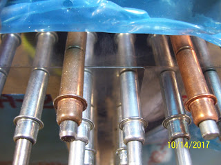

 When I re-clecoed the skins, the fuel tank skin and top edges of the inner and outer wing skins were slightly interfering with each other. I think this may have happened as a result of deburring the tank ribs, baffle plate, and Z brackets, where the tank assembly, and therefore the tanks skins, are sitting just a bit lower than before. The interference is such that a little more edge deburring by lightly sanding each skin will take care of this minor interference. So I am close, but still have a little more material to remove. Hopefully I can finish this process tomorrow.
I then realized that in order to scarf the joint properly, I would really need the skins to be secured as closely as possible to the way that the would be riveted to the wing spar and the ribs, so that I would know exactly how much the skins would need to be tapered (scarfed) to remove the .025 ridge that sits higher than the fuel tank skin when the wing skins overlap each other. They overlap each other by about 1.25 inches or so, with the side by side rivet holes about 7/8 of an inch apart from each other, and each outer-most rivet hole in each skin is set at about 5/16ths of an inch from edge of each skin.
As I thought through this, I realized that although I had countersunk the holes for the inner wing skin rivet that attach it to the wing spar flange, I had NOT yet re-countersunk the rivet holes in the wing spar flange for the outer wing skin. I needed to do this BEFORE scarfing the joint, to ensure that the wing skins were seated properly in the slightly over-countersunk holes, so that the skin edges are sitting flush against the wing spar flange.You cant set a scarf joint very well on two skins that are pillowing where they attach to the spar, so this had to be done beforehand.
SO I grabbed the drill and the MS countersink bit that was still set for the slightly deeper countersunk hole, and started re-doing all the holes for the outer wing skin attach points on the main wing spar flange on the top side. I started from the outboard (wingtip) end and worked my way back toward the fuel tank, which was still mounted on the wing spar. And that's where I ran into my issue. the wing skins overlap each other at a point that extends beyond the outboard end of the fuel tank skin. Therefore there are a small number of additional holes that lie directly under the fuel tank skin that also must be re-countersunk. The problem is that with the tank skin in the way, you can't set the microstop countersink bit flush up against the spar flange to ensure an evenly drilled hole. SO the fuel tank has to come of the wing AGAIN in order to finish countersinking. (UGHHHH)!
I removed the tank attached to the baffle plate this time, and then I realized something else that I also needed to do. This was the first time since I drilled all the tank baffle plate - to - Z bracket holes that they would all be exposed so that I could check the spacing and edge distance of the new holes in each Z bracket. I think they turned out exactly as expected. Here are some pics:


Next is a really blurry pic of the holes that lie under the nut plate holes for the fuel tank attach screws. You can still see the rivet I put in the hole to show that is has the proper amount of over-countersunk depth as specified by Vans in the latest section 5 revision of their manual.

The skins need to be tapered in this corner so that the gap between the outer skin and the wing spar flange no longer appears, and the two overlapping skins join together flush with each other, and the edges are also flush with the edge of the tank skin.
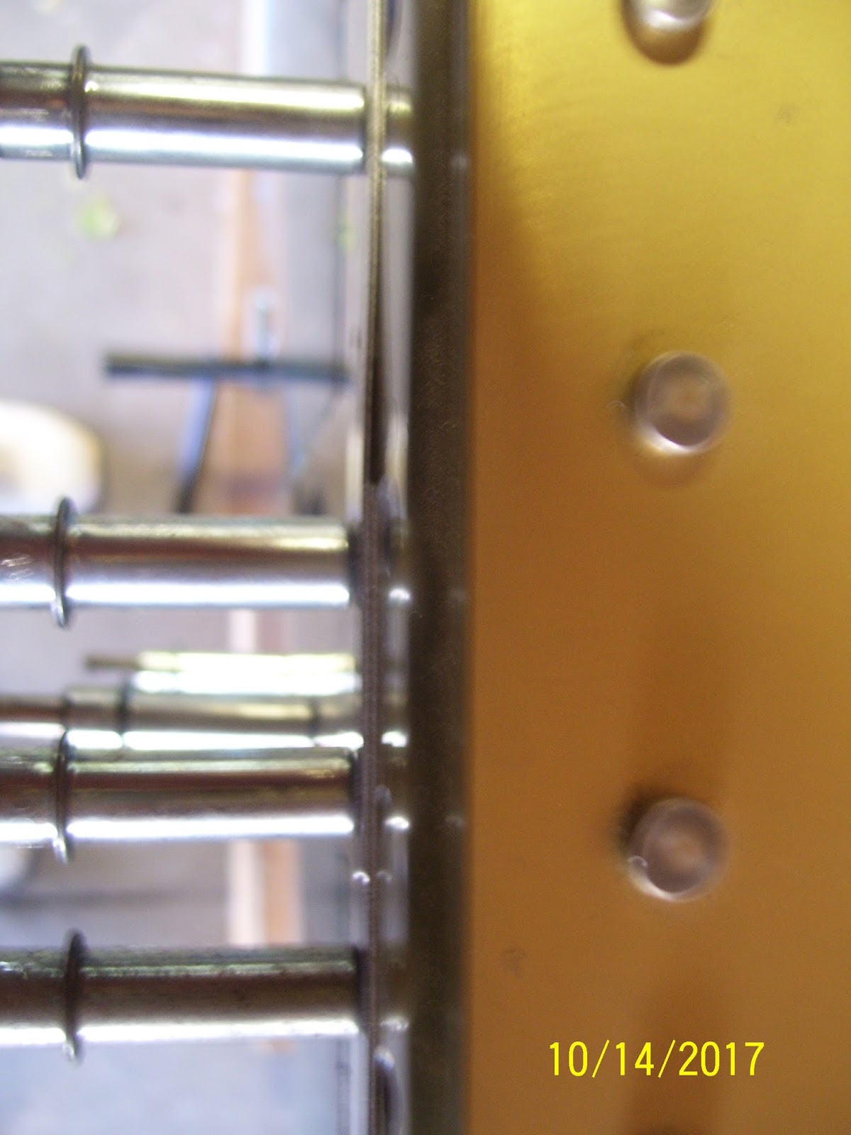

Others will perform the task with the skins removed from the spar completely, but since the object of this task is to carefully trim down the skin so that it forms a smooth, flush joint with the wing spar flange and the fuel tank skin, the only real way to do this is to start removing small amounts of skin and then check the fit. The only way I could figure to do this efficiently was to keep the skins partially clecoed to the wing frame on the most inner and most outer ribs, leaving the center section completely unattached from the spar, so I could lightly bend each skin back without creasing or kinking it while I grind away the metal a little at a time.
Now for the tools to do the job. Here is a pic of the choices I had. I had the pneumatic die grinder with a 3 inch attachment that holds a screw on attachment for a scotch brite pad or a sanding disk. The scotch brite pads seemed a little uneven to me for this application, so I opted for the 180 grit sanding disk. I also opted for the cordless drill instead of the air grinder so I could have a little better control. I also decided to use the 2 inch attachment instead of the 3 inch attachment, again for better control and to keep the area being removed as small as possible to avoid removing too much material from too large an area on each wing skin.


So this means that you have to remove a certain amount of skin thickness from the corners of both skins to arrive at the combined removal of .025 inches.The "formula" I came up with was to remove .0200 inches from the thicker inboard wing skin, and .0120 inches from the thinner outer wing skin. Now this sounds fine "on paper," but in practice I found it rather impossible to get an accurate reading from a digital caliper while trying to periodically check thickness in between sanding sessions to see of the correct depth has been reached. The other complication about this is that the skins are supposed to be tapered (scarfed), so if done correctly, the skin changes thickness constantly. So I gave up the caliper approach, and resorted to visual checks of the fit by pushing the skins together and checking for flush against the fuel tank skin.
SO you might ask, why go to all this trouble for a lousy skin joint. Well, the problem is that the overlapping wing skins cause a rise in the skin that sticks up higher than the fuel tank skin, which also serves as the inboard leading edge of the wing. If this skin edge is not made to be flush with the fuel tank skin, it sticks up into the airflow, disrupting it, causing drag and unstable airflow over that portion of the wing. So to prevent all the ill-effects of this, you need to blend the skin joint so that everything is smoothly joined together.
The other thing to note about this process is that you need to leave the flatness of the inner wing skin against the wing spar flange, so that means you only remove material from the top side of that skin, and the bottom side of the outer skin. EDIT - I later determined that I needed to remove it from the other side as well, so I removed material from both sides o the inner wing skin. You also try to keep the scarf joint a couple of inches or so in size, focusing only on removing enough material for the joint in this corner of the skin to be flush with the tank skin. It should not be a large scarf joint.
I'll add more pics of that tomorrow, but for now here is the joint after I worked on both skins a little tonight. I bent out each skin just enough to separate it from the wing spar and allow clearance for the drill and the attachment. I held the skin in my left hand, applying pressure against the sanding attachment applied to the other side of the skin, and started removing small amounts of material at various intervals, checking my progress as I went. When I felt like I might have enough material removed, I checked the fit. When I thought I had it pretty close, I re-clecoed all the skins to the frame. I've still got a little more work to do tomorrow, but I think I am on the right track.


Subscribe to:
Posts (Atom)