Showing posts with label Safety. Show all posts

Tuesday, December 26, 2017

Riveting the Trap Door

Here is a pic of the lower hinge assembly with the trap door riveted in place. I used my manual rivet squeezer for all the rivets due to the slippery nature of the hinge metal and the tight quarters that the squeezer needed to fit into, requiring a bit more control than if using the pneumatic squeezer.

The rivet on the left was the first one that was set, and of course, this being the first rivet I have set in quite a while, it naturally got messed up and I had to drill it out an reset another one. In the process of that the ends of the door next to that rivet bowed a little bit, and so even the replaced rivet is not very well set. Thoroughly aggravated by this, I decided to leave it alone before I caused any more damage to everything.Here is a blurry view of the bottom side. this actually turned out OK.
And here are the flush sets that I used in the hand squeezer with a standard 3 inch Yoke:
I used the larger 1/2 inch wide by 1/8 inch thick flat set against the manufactured head of all rivets, and the smaller 3/8 inch wide by 1/2 inch high flat set for all shop heads. I did it this way to ensure that the set would not accidentally end up hitting the hing rings, deforming them so that the pin would not rotate freely. This worked OK except for that very first rivet.

For the top hinge rivets, I was able to set the first one relatively easily, but the second one required the use of my bench vise, and a spare piece of wood that would fit inside the the flat part of the rib web surrounded by the stiffener ring on the outside. I need both hands to ensure that the rivet sets would be positioned properly and not screw something up - like smashing the stiffener ring, thus ruining the entire rib and forcing me to start over.
While I did not get a pic of it clamped to the vise, here are the pieces that were positioned onto it. The vise was lightly clamped, just enough to secure the rib so that I could position the squeezer and set the rivet.
Here are the shop heads - you can see how close the one is to the edge of the stiffener ring to get an idea of just how tricky it was to position the squeezer to set the rivet.
And here is the other side with everything riveted together:
Now, can you see my next dilemma? I still have to decide how to "secure" the other side of the hinge. This turned into yet another head scratching moment, and caused me to wonder of I should have trimmed and bent the other side of the hinge pin before I riveted everything in place. Unfortunately, I did not do that. Now I have to figure out how to accurately bend this pin with everything now tightly secured to the rib web.

This revelation led to yet another interesting observation. It involves a decision about how tightly or loosely to leave the other side of the previously bent hinge pin, and the same question for the bend to the pin on the other side. too much lay will allow the pin to slide from side to side a certain amount, and over time this would run against the rib web and/or the proseal in a very critical area of the tank that is very prone to fuel leaks as a result of it not getting sealed enough in the corner between the rear rib flange and the other rib flanges. It could even start scratching against the rib web, and I have already seen some evidence of this.

But none of these things was as disturbing to me as what I discovered while checking for freedom of movement of the door. Sometimes the door would not open when the rib was in a position where the gravity should have caused the door to open easily. A closer inspection revealed that this would happen when the 90 degree bend in the hinge pin would get forced very close to the first hinge rung that it encounters. This was effectively locking the door in place, not allowing it to open, similar to this next pic - and this is NOT good.

A closer inspection of the pin revealed why this is happening:
The pin is not bent at a perfect 90 degree angle. There is a slight amount of bend on the pin just prior to where it actually bends 90 degrees, and this bend is slight enough to allow it to be inserted into that first hinge rung if that end of the pin has any force exerted on it.I think I can try to straighten it a bit where it won't be as much of an issue, but the problem is you are just trading one bend for another one - that one being the 90 degree bend in the pin. Now matter how hard you try, there will still be a potential situation where that end of the pin with the bend in it can cause friction when forced up against the rung in the hinge.

So right now I have mixed feelings about this, and they consist of everything from abandoning the entire flop tube assembly to doing the "best I can" with the hinge pin and not worrying about it too much. Whatever I decide to do, I just do not want to ever run out of fuel for any reason unless I intentionally want to drain  tank completely for some reason.

I could not get the pic to focus properly, but you can still see the small bend in the straight part of the pin just before it gets to the 90 degree bend. I have some small hobby pliers that I think I can use to remove that small bend on that side of the bend and complete the bend on the other side as well.

What a pain - and look how much this has time sucked the build - all for a little door in a rib - crazy.

Sunday, November 12, 2017

More LE Prep and Other Stuff

Been busy doing several things since the last post. For starters, I finally replaced the stupid hydraulic jacks with a proper screw jack assembly. I already had one of these from a previous builder/s wing stand, but I could not find the other one, so off to HD I went to get some hardware. To make these you need a 12 inch long by 3/8  x 16 threaded rod, one 3/8 inch nut, and I chose use 2 3/8 x 1.25 inch wide washers. then you need a wood base that is tall enough to ensure that you can adjust the rod without over extending it too much.

I already had my wood base, and that did not change, except that I had to drill a 3/8 inch hole in the base wood to allow the rod to freely rise and fall inside as the nut is adjusted. Here are some pics. The first is of both the old hydraulic (worthless) jacks now sitting on the shelf doing nothing:

These have been replaced by 2 screw jack assemblies using the previously mentioned parts. After the holes were drilled in the base wood, I needed to drill and tap the piece of wood I have been using in order to secure the other end of the rod. I used a 5/32 drill bit to drill a pilot hole not all the way through the support wood, and then I used a 3/8 x 16 tap to create some threads. then I screwed the rod into the the support wood until is was securely in the hole.

When everything is done all you have to do adjust the height is screw or unscrew the nut to raise or lower the threaded rod, which raises or lowers the support wood resting against the rear spar web. No more having to keep re-pumping up the hydraulic jack every time I go out to the garage. SO why did I not do it this way a long time ago? Well, if you look at the drawing from Vans plans that shows this assembly, they show a rather simplistic but OBVIOUS picture of what looks like a bottle jack holding up the middle of the frame while it is on the stand. So I thought OK, I'll do that too. What a crock. Anyway, it's done now, and the left wing assembly was checked for level again by running the fish line across the holes in the main wing spar flange and adjusting the nut until the line runs through the middle of the spar flange rivet holes. Here is the left and right assembly in place:

Since I intentionally set my frames to rest a bit high in  the stand, I have to use quite a bit of wood to raise everything up to the correct level. I did that so that I could suspend the flaps or the ailerons from the trailing edge of the wing and still clear the floor.

the next thing I did was take a mirror to check the clearance of the joiner strip and the outboard fuel tank rib. I have reported in several prior posts that my "strip" did not exactly end up being 11/16th of an inch from the LE rib web as called for in the plans. In some places it ended up slightly less, and in others slightly more. This seems to have been confirmed after I was able to set a flashlight inside the new access hole and used my mirror to check the gap between the rib and the joiner plate. On the top side I ended up with more than enough clearance, but on the bottom side the clearance is just barely there, meaning that the joiner plate edge just about touches the fuel tank rib flange.

The reason that this is important is that at some point that fuel tank rib flange is going to be sealed with proseal and riveted in place. A combination of excess proseal in this area where the joiner plate is supposed to be flush with the fuel tank skin might be interfered with from the excess proseal. There is supposed to be a 1/6th inch gap all the way around, but mine obviously are not that way. I don't have pics of it but will try to get some for the next post. it is always interesting trying to use the mirror to check certain things. You could give a demo class on this subject alone, because it is more of an art than a science to figure out how to position the mirror just right so that you can see exactly what you want to see.

My plan for this is to continue with all the other stuff I need to do on the LE, and then when I am ready to take it off the wing again I will leave that LE rib and the plate attached, while I remove the rest of the LE (You know, the way I SHOULD HAVE done it the last time I tried to take it off), so I can more easily check the clearances of the joiner plate with the fuel tank rib. Trimming excess material is never a problem, but I want to better understand the reason why there is such a difference between the top and bottom sections first.

The other reason why it was important to double check this was because this may also have been contributing to the gapping problem between the outer LE and fuel tank skins that was giving me fits the other day. Need to check clearance with skins, ribs, Z brackets, and the baffle plate to make sure nothing is interfering with the fit.

Now that all that madness was done, it as time to remove the blue vinyl from the first bay of the LE so that I could make some final measurements and draw the final lines on the skin that will be used to mark the rivet lines, cut lines, and nut plate lines for this lovely time-consuming mod of mine. taking pics of bare metal is always a challenge, so these dd not come out exactly the way I wanted them to, but they will suffice for now.

Here is the bottom of the LE skin with the basic drawing of the planned cutout. I decided to use .75 inches as the rivet line mark from inside each existing rivet line for the rivets that will attach the ribs to the skin. The next decision was to use 5/16ths of an inch as the edge distance from the new rivet line. This will become clearer when I start drilling the new holes for everything. I decided on 5/16th of an inch because in other areas that could be construed as a "splice joint" per AC 43.13, such as the main wing skin overlap, the vertical edge distance of those wing skin rivets is 5/16ths of an inch. What's good enough for the goose is good enough for the gander, as they say.


I am using a 1/2 inch radius for the rear side of the removable LE, similar to the same radius used for the new access panel cover. In  fact, I took one of those covers that already had that radius built in to it to trace it onto the LE skin.

These last couple of pics show a line that drew on the top side of the LE skin between the 5th rivet hole from the front of the LE. After spot checking the rivet hole layout of the LE ribs on the top and bottom flanges, I discovered that the 5th rivet hole on the top is almost directly vertical to the 4th rivet hole on the bottom. The concern about using the 5th rivet hole on the top as the line where I will make the cut, is that there is still a pretty substantial amount of bend in the skin at that point. one of things I need to be careful about is to make sure that the removable part and the remaining LE skins will retain that curvature after they are fastened with screws or rivets to the subskin. I can perform some tricks that will apply a slight curve to the edge of the removable part if I need to, but I was hoping not to have to perform too much of that sort of magic.

The other, much more important concern about this, is if a crack forms or a screw come loose from a nut plate on the top of the LE. If this happens, and the skin is allowed to rise up into the slip stream, it basically turns into a spoiler, that will disrupt flow over the top of the wing, and, at best, will cause me to loose lift. At worst it can cause that part of the wing to stall, or for part of my aileron authority to be lessened, or lost entirely. (THIS is that part of the safety concern about this mod that I have been talking about ever since I thought it up.) Needless to say, my pre-flight inspections  will always consist of a significant amount of time devoted to checking ALL of the rivets and screw attach points on the top and bottom of this area, before I even think about getting in the airplane. All screws will be checked for tightness and the overall condition of this area will be scrutinized heavily.

I need to finish drawing more reference lines on the top and bottom side of the LE, and then I will mark all the additional rivet holes that will need to go through both the outer skin and the subskin and drill those. Then I need t make some final decisions about the number of screw holes along the sides and trailing edge of the areas in question, and drill #30 pilot holes through the outer skin and the subskin. Right now I am thinking about 4 screws along the back side, and 2-3 screws along the inboard and outboard edges of the bay. So I am finally and literally at that crucial point in all this prep work. If I screw any of this up now, there is no turning back. I may ask a tech counselor to come by one more time now that I have made some decisions about edge distance and rivet spacing.

Till next time,

KPR


Monday, February 25, 2013

A Young Eagles Flight Adventure - - NOT!

Editors Note****** I revamped this story just a bit to make it easier to read and corrected some obvious grammatical and spelling errors. Apologize to my readers for that. This version should be much better.

It turned out to be a pretty nice airplane work session over the weekend, despite getting nailed with tons of snow Saturday evening into Sunday. Before I cover the details of the build, there is something else I thought might be worth mentioning that happened to me early Saturday morning. It concerns a matter of aviation safety, and I thought that other pilots might benefit from it.

I was planning on flying Young Eagles Saturday morning at KFTG for the second YE rally of the year. YE flights have become so popular that the chapter rallies that are held each month are booked at least a year or more in advance, and EAA Chapter 301 cranks out about 50+ first flights for kids during each and every rally. I feel privileged to participate in this event, and even moreso when I get to fly.

Anyway, since I do not yet own my own airplane, I have to resort to renting an airplane from the local flying club. One thing that really concerns me is how extremely expensive renting an airplane has become compared to when I first learned to fly in 1980. I am frankly a bit shocked at the state and age of equipment that exists in most flying club fleets these days, compared to the grossly out of proportion rental rates that they charge. Personally I think it is just another example of American greed at work here, but I digress.

Chalk it all up to another of what I would rate as my top 5 reasons for wanting to build and own my own bird. The aircraft that are currently available for rent are a mix of old and new, and the equipment and avionics in these older model aircraft is pretty lacking. The problem that I see is that they are charging expensive rates for newer aircraft of the same model, and they are also basically charging you the same rate for an aircraft that, from an equipment/avionics perspective, does not even come close to what the newer airplanes have. I can't believe that the cost of insurance, maintenance, and fuel are making these older airplanes just as expensive to fly as the newer ones. In fact, I think what is really going on is that they are using the older aircraft in the fleet to help cover the actual cost of renting the overly expensive newer models. This is nothing short of robbery IMHO, and is  truly a sad state of affairs for those wanting to learn how to fly today.

Anyway, I had scheduled a C-182 for the flight on Saturday, and the weather was perfect, except for it being extremely cold and prone to frost in the morning. Gee - sounds like deja vu from the first time I did this in November of last year. So I arrived at the airport (KAPA) early in the morning before the club opened. I had scheduled an early morning departure so I could arrive at KFTG by 0745 local for the briefing. The club places the aircraft books and keys in a lockbox and you get the combo the day before so you can retrieve it without waiting for the office to open up.

So I  opened the lockbox, and my airplane book is nowhere to be found. A couple of folks with access to the office had also shown up early, so I was able to sneak into the office, and sure enough, found my airplane book sitting neatly on the shelf. Not to worry yet - perhaps it went down for maintenance, but I would have expected a note or a phone call had that been the case - but I received neither. Anyway, I retrieved the airplane book and headed out to do the preflight so I could be on my way.

I opened the airplane up, and alas - it was almost starved of all fuel. This is not uncommon for a C-182, which is a prime cross country airplane, having flown several hundred hours in them during my former years as a Civil Air Patrol Search and Rescue Pilot. Still no problem - called the fuel truck and the fuel was on the way. Then I turned on the Master switch to lower the flaps and began my preflight - so far so good. Everything else inside the cabin checked out, or so I thought, so I then proceeded outside to walk around the airplane. As I reached the tail one of things that is routinely done is to check for freedom of movement of the control surfaces. This is done by physically grabbing the elevators and such and moving them gently from one extreme to the other. If everything is normal, you hear and feel nothing other than the smooth operation of the counterbalance springs, and perhaps some slight noise from the hinges that attach it to the HS. Unfortunately for me, I hear this very loud squeal and a very distinct grinding noise, all coming from inside the cabin. I returned to the cabin to move the controls this time to see if I get the same noise. Sure enough - the co-pilot side control yoke was starting to bind on something, but the pilot side still felt OK. Both yokes are joined together behind the panel so that either of them can control the same control surface.

This became an instant deal breaker for me. Sure, I could overcome the slight binding with normal control pressure, and the noise, while disturbing, was not ultra-overpowering to me - just annoying enough to catch my attention. The problem was, and my thought process was, what if it gets worse after I become airborne - what then? What if they totally freeze up during a critical phase of the flight? Even more importantly, what if I encounter this problem with a Young Eagle and their parents onboard for their very first small airplane flight? I was not willing to even remotely consider that possibility. So the decision to abort became relatively easy when I took the well-being of my passengers into account.

Having had this grinding noise type of problem before, I new that it had something to do with the mounting bracket or bearing on the copilot side controls. Unfortunately, since the pilot and copilot control yokes are mechanically joined together, they both need to be working properly or else you may have a problem.

By now I recognized that I was starting to experience something that I have taught countless other pilots to recognize over the years. I call it the "3 strikes and your out rule," but it is also better known as the "catastrophic chain of events" in most post mortum NTSB accident reports. No matter what you call it, it often times leads to an undesireable outcome for a pilot and their passengers. The premise is that most aircraft accidents are not attributed to just one single factor, but are usually comprised of a series of linked events that lead the pilot further and further toward a devastating outcome, driven by the series of actions or inactions taken by the pilot. Pilots must learn to recognize when they enter into this situation, and then take the necessary action to break the chain.

Strike 1: The airplane book was not available, making me late and pressuring me ever so slightly to hurry up and get going. There was a possibility that the airplane had been grounded without my knowing it. Action - I chose to preflight anyway and then further assess the situation after that was done.

Strike 2: No fuel in the airplane - more time wasted - more pressure to hurry, but this was also expected, and was of the reasons why I arrived early enough take care of it.

Strike 3: Grinding noise and binding of the control yoke - Ok -  this was not something I was willing to compomise on. If it don't work right, and the potential outcome might be very bad - don't risk it. I broke the chain right here.

And then came yet another strike. Strike 4! It was as if it was affirming my decision not to fly, or at least that is how I took it. I needed to raise the flaps back up and secure the airplane so I could return to the office. But when I actuated the switch, nothing happened. No upward travel at all. I then thought I could try to lower the flaps all they way down and then back up to see if that would work, and it did, for a moment anyway. The flaps came back up to the point where they had about another 10-15 degrees of travel remaining, and then the flap motor cut in and out several times until they finally retracted to the full up position.

I returned to the office, reported the problems to the dispatcher, who by this time had opened the office, and then I left for home. The one thing that disturbs me is that the airplane had flown the day before, and I can almost assure you without a doubt that the control yoke was exhibiting the same behavior on that flight,  but they flew it anyway.

It is decisions like this that face pilots on every single flight, no matter if it is an airliner or a small GA airplane, some of the decisions that must be made are very much the same. I wanted to jot down this experience in my blog to hopefully benefit any fellow pilots that may read it.  I wanted to reaffirm to others that there is absolutely nothing wrong with saying that you probably won't get to go flying today... Better to live and fly another day than to die and never get the opportunity to do it again. Extra vigilance must also be applied when flying unfamiliar rental aircraft that may be in less than "mint" condition.

I was proud of myself for making the decision to stop the ever-progressing chain of events that were unfolding before my eyes, but still frustrated about the whole experience, and the realization that I was not going to get to participate in this month's YE rally. This is the reality of being a pilot -sometimes you just have to say "not today."

Instead, I chose to view this experience positively as follows:

-I went home and started working on MY airplane - so the day was not a total loss at all.
-I am using these experiences as strong motivators to finish my project someday. I am so sick and tired of dealing with flying rental airplanes, and schedules that don't match mine, and airport security crap, etc., that I am more than willing to continue the long and expensive process to one day own and operate an airplane that I built with my own two hands.
-I may have saved someone's life by taking the action that I did to ground the airplane and demand that it be repaired. That is perhaps the most rewarding feeling of all, and in the end is really what all the preflight preparation is all about.

The moral to the other pilots out there:

 Don't forget about the reasons why you perform every step of the preflight checklist, and how important it is to do it right, and to pay attention to what your senses are telling you. Part of the problem is that flying has become so reliable these days that we rarely have to face a problem serious enough to force us to make an outright no-go kind of decision.

So if this sort of thing happens to you, recognize the events that are unfolding around you, evaluate your situation and potential options, understand the risks for taking each option, and make the correct decision - even if the decision you will have to make is to stay on the ground.

Fly safe, and all you builders out there don't forget to fly every once in a while!

Sunday, February 13, 2011

217 on the hobbs. Rudder Skin deburred, dimpled, stiffeners dimpled & final trimmed.

Warning..... This post is created with captions on top, and pics associated with the captions underneath. Didn't want anyone to get confused about which pic goes with which caption! Warmer weather is finally upon us, so the goal this weekend is to get as much prep work on the ruder completed as possible, and get it all primed.

So here is a shot of me with rivet gun in hand, ear muffs on head. I used my close quarter dimpling tool that I have raved about so much in previous posts to dimple the stiffener holes in the rudder skin, because trying to get to these with the C frame was too difficult. As you moved closer to the bend in the rudder the skin would start to lift up as you pull back on the other side of the skin to access the hole and provide enough room for the hammer to strike the ram on the C frame tool. This would basically form a dimple that is not perpendicular to the rudder surface, which would cause the rivet not to seat correctly. So, to avoid that little problem, I switched to the close quarter tool, which, as you can see, leaves the skin flat on the table for the most part.

Note the ear muffs. I will continue to wear these instead of the individual foam type in each ear when I am working in the winter time, because I found out that these suckers really keep your ears warm!

And here is a shot of my little helper.... My youngest son came out to help steady the rudder skin while I dimple these last several leading edge holes. The project thus far is "almost" a family affair, in that both boys have helped me with various things along the way so far, but the wife won't go near it. That is OK however, because she knows how I can get when things don't go smoothly from time to time, and so I guess that makes her the smart one of the bunch for remaining a casual observer to the whole thing so far!  :) As long as she can still get her car in the garage then she is happy, and I am happy with that as well.


Here is a close up of a finished dimple closest to the leading edge of the rudder. The round circle impressions are somewhat normal during the dimpling process, and are made from the dimple die edges that just touch the surface during the dimpling process. These will vanish from sight when the skin is prepped, primed, and painted. Notice the other two dimples above it that were created using the C frame tool. The dimples are created from the same dimple dies, so they should look similar to each other.


Here is shot of the close quarter tool from Cleaveland Tools. screwed onto the edge of the table, with the female dimple die inserted at the tip. The male counterpart is in the rivet set holder from the C frame, which conveniently fits into the rivet gun. Just always have to remember to turn down the air pressure on the gun when you do this. It does not take much effort to set the dimple - about a second or less with light taps on the gun. The rudder is made of .020 thick aluminum, which basically means it is almost thinner than a pop can! Have to be careful with it. Funny, I can pull up to 6.5 G maneuvers in the airplane when finished, and it goes together with aluminum that is thinner than a pop can - simply amazing! Of course, that is where the stiffeners come into play too.


The next pic down below is of the skin placed over the close quarter tool. The hardest part about working with this tool is finding that little hole in the die at the end of it by moving the skin around until you locate it. I have developed a "very technical" procedure - NOT - - for doing this that involves eyeballing where the bar is attached to the table. Then I line up the hole in the skin with the location of the bar, and carefully slide the skin over the top of the bar,without letting it touch anything, until I start seeing the  bar appear through the holes in the skin. Then I carefully find the end of the bar through the desired hole in the skin, and slide it back slightly until I see the hole from the dimple die line up with the hole in the skin. Then the rivet gun goes into the hole to lock everything in place.

 I also perform another ritual after having messed up my HS skin a bit when I did not get the hole lined up correctly. You can really mess up a skin if you are not careful with this, so patience is key here. The ritual is that once the rivet gun is in place, I gently tug on the skin to verify that it does not move at all. This means that the skin is correctly positioned over the female dimple die, and the male die is properly seated through the skin and into the female dimple die.

This pic also demonstrates why I needed a helper. The HS skins and the VS skins were short enough to fit between the legs of my long craft table, but the rudder is much longer, for lots of aerodynamic and flight performance reasons that I will not go into right now. You can see the left edge of the rudder jsut touching the left leg of the table. I had my son steady the skin here and ensure that it would not contact the table leg while I created the dimple. Whose big foot is that under the table? Hmmmmmm. Looks like a teenager foot to me!


Here is a pic showing the inside of the skin where the LE dimple was created. The scratches in this area around the dimple are from the scotch brite pad I had to use to debur these holes, since I could not fit my deburing tool inside there. The scratches are not as pronounced as they appear here - the light reflected off the skin, making them appear more dramatic than they really are. Only light scuffing was needed to debur the hole. As for appearance, the inside of the skin will be primed, so the rest of this area is going to get scratched up shortly anyway, in preparation for priming. Just needed to get the hole deburred first so I could form the dimple.


This next pic is testament to my horribly un-level garage floor. Another hard lesson learned was to ensure that the table legs are firmly planed on the floor. Since I basically have no level surface at all in my entire garage, I needed to shim the table legs in a couple of places to ensure a solid, stable work surface.


And finally, a shot that shows just how wintery it is outside, while I continue to slave away in the bitter cold. I call this little mountain Mt. Bryan, located just off the edge of my driveway. Come on spring!!!! Time to head back out to the garage.... almost 60 degrees outside - lovin it!


Sunday, November 28, 2010

Trimming Stiffener Cont'd.


This is a pic of the safety glasses, ear plugs, dremel tool, and the scrap aluminum pieces you end up with when you are done cutting all 16 stiffeners. Note how sharp looking these are. it is important to clean these up and ensure that they are picked up off the floor as soon as they are cut. I could think of no useful purpose for any of this scrap material, so it ended up in the 86 files (trash). Recyclers will now respond and attack me "En masse" for doing such a foolish thing. So it goes I guess.

Tools, Safety, and Trimming the Stiffeners


I used my dremel tool to cut the stiffeners from the aluminum angle. Other tools included clamps, Safety glasses, ear plugs, and several REINFORCED dremel cutting wheels on the standard Mandrel. Do NOT use the small standard NON-REINFORCED cutting wheel as these will shatter as soon as you hit the aluminum. The reinforced cutting wheels will work fine, but you will go through at least 4-5 of them in the process of trimming all 16 rudder stiffeners. The wheels dissipate quite rapidly when cutting the aluminum, so you will need several of them. You MUST where safety glasses and ear plugs, and, as I found out the hard way, even some gloves to keep from burning yourself on the hot dremel tool.

The last thing you need is tiny shards of aluminum in your eyes. Believe me, there are plenty of them hitting your face as you cut the metal. If you are less inclined or do not possess a Dremel tool then a good hack saw or metal cutting blade will work fine. I set my Dremel to a 9 power setting (Almost full speed). I did not want to experiment with a slower setting for fear of binding the aluminum causing the wheel to jump and cut things other than those you originally intended to cut.

Tuesday, March 30, 2010

More Priming preparation

Some additional photos that show my painting preparation and equipment.


This shows part of a length of aluminum wire in black shielding that I removed when I was getting my shop in order for the build. I decided to remove the aluminum wire and replace it with the correct copper wire, but I decided to keep the strands of old wire instead of throw them out. Good thing I did, because I am now able to tie it off across the garage to serve as a hanging wire for all the parts that I need to primre or paint. I use 14 gauge grounding wire which fits nicely through the rivet holes of the parts, and hang the other end on the aluminum wire strand as shown.

A frontal view looking into the garage. Its best to enlarge this photo to see a bit more detail. Just click on it, or any other photo, to do so. This shows almost the entire strand of hanging wire. The parts you see are avouple of the ribs and one of the rear spars of the HS.


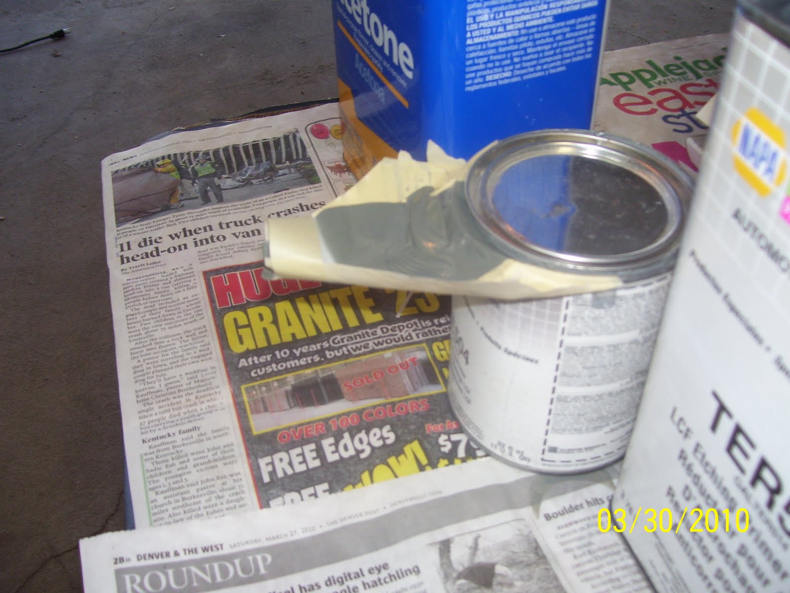
This is a pic of a poor man's funnel trick that I learned a long time ago. I tried using the plastic pour spouts from HD on the quart-sized can, but it just would niot stay attached. The last thing I need is a bunch of acid etching primer flying into my face and eyes because I used the wrong tool for the wrong job. SO, I used masking tape, and overlap it into a square just a bit larger than the circumference of the can, and trim it to size and to a point on the front. Then I take a another piece of tape, and pull the front of the tape together, to make a spout. The rest involves making it wide enough to accept the amount of primer you will pour out. Once it's done, it works very well. Keeps the top of the can clean and provide a workable pouring spout that won't leave a mess.


This is a shot of various must-haves for priming and painting. They consist of:
A card table
a Post It Note Easil with a built in stand
Newspaper - lots of that!
and a large supply of wash cloth-sized micro fiber towels.
Medium sized paper funnel strrainers
You can see the test spray pattern I made on the easel while setting up the gun. It serves as a great test platform, and you can spray a page, rip it offthe easel, and have a new clean page to work with very quickly while you adjust your spray gun settings. Its about $30.00, so it's not cheap, but still highly necessary in my opinion.


These are the brand of micro fiber towels I use. These are great for wiping things down with Acetone or for any other application where you need a non-abrasive cloth or rag.


A Halogen light I ahve had for many years. One thing about painting - you never have enough lighting. I am in the middle of working a solution to that very problem by getting more light focused on the parts on the hanging wire. It is very difficult to see the coverage of a gray primer applied with a spray gun on a small metal part in a poorly lit garage. The problem with these lights is that they get extremely hot, and are prone to the safety glass imploding or the bulb exploding if you drop it or bump it ever so slightly.


Not a very good pic, but these are more safety items that I use. I have three different sets of safety glasses, one for general impact, one for fluid protection, and chemical-absorbing respirator. Last but not least are the rubber gloves - lots of them.
This is quite a bit of stuff, but it makes the paint preparation and application go so much smoother. I find that I can set everything up in a matter of about 5 minutes, and tear it all down when I'm finished so I can put the cars back in the garage for the night.