Picking up from my previous post, the hinges, door, and spacer are fabricated. Now it is time to position everything on the rib and drill the necessary rivet holes.
Here some pics showing how I drilled the upper hinge rivet holes:
And here are the holes in the lower hinge:
And this is where is starts to get more challenging. The next step is to countersink the right holes in the right part. It goes something like this:
- The lower hinge is only attached to the upper hinge via the hinge pin, and to the actual trap door.
- The trap door holes get dimpled, and the back side of the lower hinge holes get countersunk.
- The upper hinge is attached to the spacer and then finally to the rib web. SO in this case the top side of the upper hinge is countersunk, and the rivet then goes through the holes in the spacer and the rib web.
So you have to make sure that you countersink the right holes on the correct side of each hinge. If you screw that up, you get to start over. Perhaps this is not an issue for other folks, but for me it was a bit unnerving. Hinges are a bit strange for me to work with, because they are made from a different alloy, with a different hardness, and a different thickness than other types of alclad aluminum.Their dimension and general shape also make them a challenge to work with.
One of those challenges is that I find it difficult to try to setup the work so that you can use a microstop countersink tool to drill the holes - mostly because the holes are typically very close to multiple edges of the hinge, an the part is small, so the tool does not sit well. The shape of the hinges also makes it difficult to butt up multiple hinge halves to give the tool more surface area to sit on, as I have done in other situations when working with flat aluminum alclad.
So, I resolved to countersink the less elegant and more error-prone way, by using my deburring bit in my cordless drill, and carefully countersinking each hole and trial fitting it with a rivet to ensure that I don't go too deep. Here I am burrowing out the holes in the back side of the lower hinge that will accept the dimples from the trap door.
And a test fit with a rivet. Not the best job, but its good enough for me:
Its OK if these are a little deeper than flush, because they will need to accept the dimples from the trap door. Next came the fitting and drilling of the holes from the upper hinge half in the spacer and the rib web. I found this to be the most challenging part of this little project. Had to get downright inventive about how to clamp that sucker down and position it exactly where it needed to go to ensure that door ends up in the right position. I found a small clamp or two that seemed to work out well enough - as able to insert it through the fuel feed hole in the rib - you know - the hole this door is trying to keep covered some of of the time:
After using the hinge to match drill holes in the rib web, I then needed to match drill the same holes through the spacer. I drilled the first hole through the rib web to the spacer, and then I needed to re-position the clamp to the corner of the spacer in order to hold it in position well enough to drill the other hole.
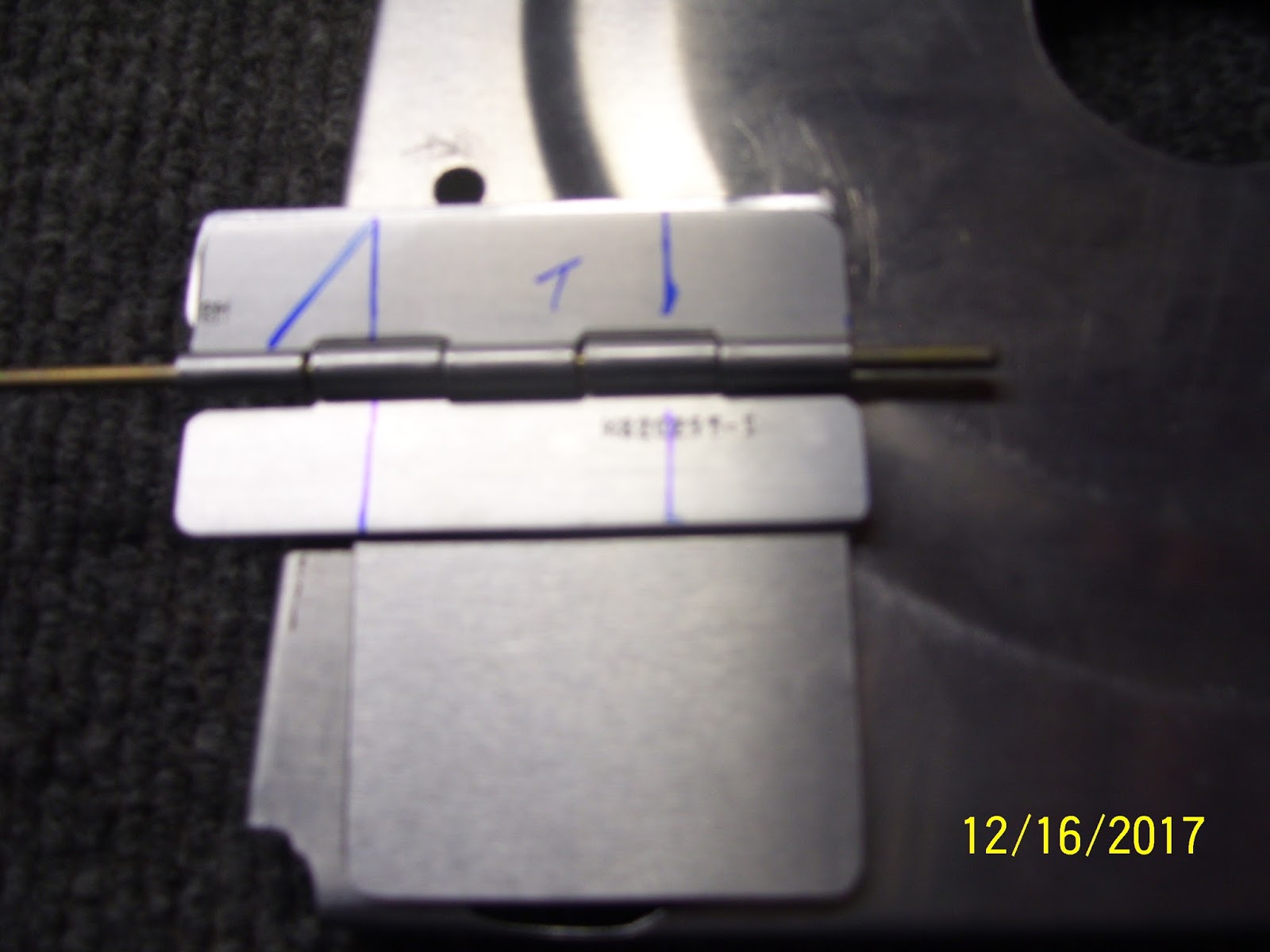
once the upper hinge and spacer were drilled to the rib web, next came the lower hinge and the trap door as shown here. decided to mark the hole locations in the door so I could remove the assembly from the rib, since none of these holes are going to go through the rib. I did not want to risk accidentally drilling into the rib web, so I marked the holes on the door with a sharpee so I could realign them again after removing the hinge and the door from the assembly
I put a piece of tape over both parts before removing them from the rib to help keep them aligned with each other.
Next was another trial fit after the holes were all match drilled and countersunk, etc.
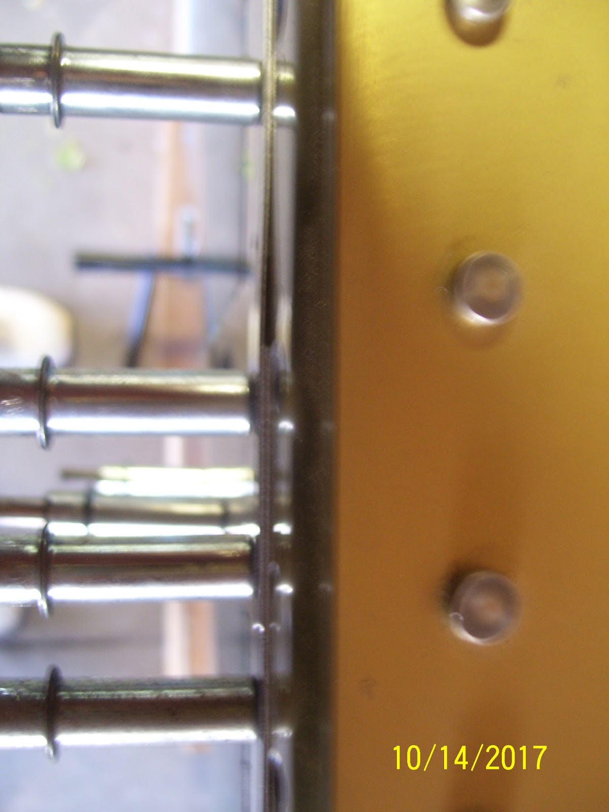
And then finally is a shot of the two upper holes and where they ended up in the rib web. You can see from this pic just how close to the edge of the stiffening ring it is. This shot also demonstrates the question one has concerning how Vans seems to think that you can make three rivet holes in this area instead of the two that you see. The stiffening ring/depression makes this virtually impossible.
On that note - just one more thought about this whole situation with the fuel tank and this whole trap door fabrication business. One of things that I have become very aware of as I have continue to work the fuel tanks is the need to ensure that anything that is attached in a certain or is added to the tank assembly MUST NOT fall apart, break off, or become loose and fall off while inside the tank. In one case you might experience odd behavior with the fuel system, and in the worst case you may experience a blockage in your fuel pickup line that will cause fuel starvation at some point in the system. As such, all of the parts involved in this trap door fabrication are a concern for me, as well all the parts that make up the entire flop tube assembly.
Everything from the hinge pin to the rivets to the parts is a concern, and whatever you decide to do, you have to end up feeling confident that the added pieces and parts you are putting in the fuel tank are not going to cause a bad situation in the future. You need to k now that the extra rivets are not going to break or come loose, and the clunk on the end of the flop tube will not loosen from the tube, and so on. During my research I have read many accounts of folks that have ended up with a variety of issues with the fuel tank components from time to time. And at the same time I have also ready about folks that have had trouble-free tanks for years. I guess it all boils down to paying attention to details and being very safety-minded when working on the tanks.
This trap door assembly, fuel sending unit, and the flop tube are the only three moving parts that I am will to accept inside the fuel tank. Those 3 components provide numerous "opportunities" for things to fall apart or cause other problems. Add to this the blatant fear that most folks feel about sealing up their tanks properly, and this whole part of the project can become quite stressful. That's why a lot of builders opt to have their tanks built by someone more knowledgable and experienced. As for me, I am a builder, and the only way I will become experienced is to just dive in and do it, and seek expertise from those that are the experts.
Next up will be riveting this trap door contraption to the rib, and putting the final bend on the other side of the hinge pin.
KPR
Showing posts with label Countersinking. Show all posts
Thursday, December 21, 2017
Christmas Fun and Fabricating the Imfamous Trap Door
After the flycutter episode with the most inboard fuel tank rib, the next feat was to fabricate something known as the trap door on the inboard rib that sits next to the most inboard tank rib. So this is now becoming a process of removing the ribs from the skin to prepare for the final assembly of the fuel tank.
Before I get into that whole story, I wanted to share some fun that I had with my wife a little over a week ago at a place near a local mall called canvas and cocktails. It is a place where you can go and paint something on canvas using water based acrylic paints, and have some alcohol while you do it. An instructor guides you through the process to paint the picture step by step, color by color, and brush by brush. I did this with my wife, my oldest son, and his girlfriend, and had an absolute blast. It "almost" made me brave enough to think that maybe I really can paint my own plane when the time comes. But let's not get into a rush on that just yet....
Here are our finished masterpieces - this particular painting had so many colors an shapes going on that it took longer than usual to finish it - almost 4 hours. But it was time well spent IMHO. Can you guess what it is, and which one do you think is mine or the wife's?
Now the trap door episode. What is it? Well, in aircraft where a flop tube is to be used for the fuel pickup line, and where possible extended unusual attitudes or 0 or negative G flight might be encountered, You have to ensure several things:
1. The engine has an inverted oil system
2. The fuel tank system is designed so that fuel can continue to be delivered to the engine at all times.
Vans standard design is to install a fixed, rigid fuel pickup line that stays in the same position in all flight attitudes all the time. I had decided when I ordered my wing kit to put one flop tube in the left wing and keep the standard fuel pickup tube in the right wing, with the idea that all unusual flight attitudes and inverted flight would be done with the left tank selected so that it takes advantage of the flop tube.
If you have ever built and flown gas or glow powered RC airplanes, you always had to put a heavy weighted clunk attached to a piece of fuel line inside the fuel tank. This allows gravity to keep the end of the fuel pick line inside the tank always accessing the lowest area where fuel resides. The flop tube is basically the same concept, made with some different materials and a few more fittings, but the exact same concept.
Another contraption that is also used to help ensure that fuel is always available and in close proximity to the flop tube is a so-called trap door, that is placed over a small hole in bottom rear of the next closest inboard tank rib. The most inboard rib obviously cannot contain any holes except those that contains a vent line or fuel feed lines that will route fuel to the engine from the wings and fuselage. However, all of the inboard ribs MUST contain openings that allow fuel to transfer from one bay between ribs to another bay. IN addition, the dihedral of the wings also forces fuel to continue to flow to the lowest inboard position in the wing tank, which is right over the corner where the fuel pickup line is located.
By the time the fuel gets to the last bay in the tank where it is picked up and routed to the engine, under normal flight attitudes and conditions it should generally remain in the last bay of the tank, closest to the fuselage. However, when performing aerobatics or high G maneuvers, it is possible that the fuel may attempt to move out of that first bay of the tank and back into the outer bays, away from the fuel pickup line. So to help prevent this, a small trap door is fabricated and installed on that first inner rib so that it covers the hole that allows fuel to enter that first bay in the tank. It is designed so that it opens and closes automatically as fuel pressure is exerted into or out of that bay. Any force that is applied that would allow fuel to be removed from that bay will also close the trap door, while pressure applied in the opposite direction forcing fuel into that bay will also open the trap door. There is no control linkage or motor or wires - it is just mounted with a hinge and a plate that is big enough to cover most of the opening in the rib, and is allowed to swing freely as described above.
Now for the funny part. It seems that my original reasons for wanting a flop tube in the tank may have been misguided somewhat.It turns out that the only time you really need the flop tube is if you intend to conduct sustained inverted or negative G flight. If you perform positive G maneuvers, which most aerobatics are, you don't really need the flop tube, and can get by with the standard fuel pickup line. Further more, if you keep the aircraft coordinated, fuel should always be available in the first bay of the tank, and never allow a condition where the pickup line or tube is un-ported. This then means that the trap door should also not normally be needed either.
Oh well, too late for that. Anyway I still like the idea of the trap door anyway as a bit of insurance to keep fuel in that first bay at all times. Turbulence can have a way of putting you in some very strange flight attitudes - ask me how I know....
So I decided to put in the trap door assembly since I am also going to use the flop tube. It starts with making the door itself from .020 inch thick aluminum from your trim bundle. This is thinner than a pop can and is the same thickness as the skin that was place on the rudder frame. I measured it per the plans and cut it from the sheet using left and right hand sheers. I think this was the frst time that I realize that the left and right designation does NOT apply to which hand you use to do the cutting, but rather the side of the cut that needs to be made and the amount of extra metal on either side of the cut that needs to be kept out of the way of the sheers and the cut. Never understood that, and never used these tools until now.
Next was figuring out where to get the hinge material from. the plans tell you what hinge to use, but they don't specify a part number of if this is supplied already with your wing kit. I learned from other builders that you can use a small section of the same hinge material for the wing flaps. these hinges are 6 feet long (72 inches), and a quick review of the flap assembly plans shows that only 56 inches is needed for the flaps, so they give you plenty of extra hinge material. I measured the length I needed per the plans, and marked the line. I used my Dremel cutoff wheel to cur the hinge, but I had to slide out the hinge pin first, because you need a little extra longer length of the hinge pin so you can bend the ends to keep the hinges from separating.
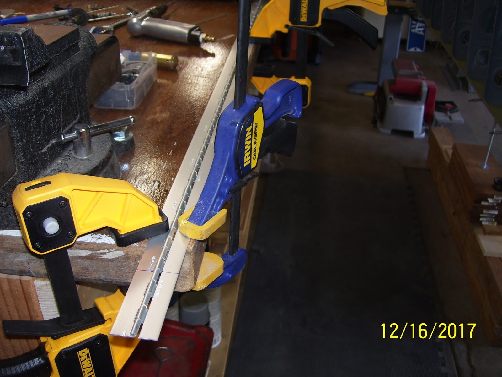
Here is how I clamped everything down to make the cuts:
One part that you also should fabricate, which the plans do NOT show, is another piece of .020 aluminum shaped to match the dimensions of the upper hinge half (about 1/2 of an inch wide). This is a spacer that allows the top half of the hinge to sit even with the bottom hinge and the door assembly, and allows the door to close as flush as possible next to the hole in the rib. Here is the hinge, the door, the spacer, and the hinge pin all cut to initial size.
Next the hinge gets trimmed a bit more to match the width of the trap door and to form the upper hinge plate so that it has a small triangle on one end. More about that in a minute:
Here is my first trial fit of the assembly on the tank rib. I adjusted this a bit more later one, but this is the approximate location for the door, very near the rear rib flange:
After figuring out how to clamp the small hinge halves down on the bench so they could be trimmed to their final dimensions, I ended up with hinges that looked like this:
That little triangle on the top hinge half then gets bent 90 degrees to act as a door stop for the door. It cannot be allow to open all the way flush with the top side of the rib, because it may never close again, allowing any fuel that is currently in that first bay to escape into the outer baffles of the tank and away from the pickup line. So to prevent this, the little tab keeps the door from opening too far s that it cannot get stuck all the way open. To bend the tab, I put it in my vise like so:
Then I used a small rubber mallet to bend the metal 90 degrees. I had to position the tab properly in the vise so that the bend would occur in the proper place. the reality is that the tab needs to be a little bit inboard from the edge of the lower hinge and the door, to ensure that the door will always contact the stop and will not get stuck:
By this time I should also mention that I had already smoothed the edges of all parts on the scotch brite wheel and rounded all corners to avoid stress risers - standard deburring procedure. After the bend the parts looked like this:
Next came the painful task of marking rivet lines. I hated this part and it took a while before I was satisfied that I had the marks in the proper position. The plans do a horrible job of showing different pics with different hinge layouts that do not match each other, and they show that there should be 3 rivets on the top hinge and 3 on the bottom hinge. The only problem with this is that there is a huge stiffening ring you know - the one on the inboard rib that I cut with the fly cutter recently. So there is a huge void in the area where the upper center rivet is supposed to go (SO a rivet can't go there). And then the location of the top forward rivet is right on the edge of the rib web just on the other side of the stiffening ring, so getting the location of the rivet right is pretty important because the shop head and the hole both need to have enough room to seat properly.
Rivets for the bottom hinge can be evenly spaced as they all will fit on the rib web with no issues.To resolve this, I decided that the upper hinge could only have 2 rivets, and the bottom would have 3 rivets per the plans. The upper hinge would need rivet holes that are the right at the minimum edge distance of 3/16ths of an inch for an AN426AD3 rivet.The lower hinge rivet holes were spaced 1/4 inch from the edges, giving a little bit more of a buffer. Here are my early attempts to mark the rivet lines. found this to be very tricky because it was hard to get a straight edge on the hinges, because they are small to begin with, and the 5052 H34 aluminum alloy they are made with is very slippery. I remember dealing with this when I had to fab the trim tab hinge. It was a pain then and it is a pain now.
Since I had not had to bend hinge pins in a while, I could not remember how I did this in the past. So I decided to try to put a 90 degree bend in the hinge pin the same way I did the hinge. It did not work so well.
I ended up taking a small block of wood with a flat surface and placing it next to the pin and and then hitting the block of wood with the hammer - worked much better, the pin is much stiffer for obvious reasons, so it took a bit more force to get it to bend, but once it was started it went over pretty well.
Next was another trial fit to mark the final position of every thing after all the parts were final-formed. You leave a small opening at the bottom of the hole beause proseal sealant will be placed in this area of the rib flange, and you don't want the door to be so big that it interferes with the proseal. Also note that this hole goes all the way to the bottom of the bottom tank rib flange.Another funny thing that I saw from other folks build logs is that most folks put bends on the hinge pin on both sides of the pin, but some appeared to only put the bend on one end. Now, if yo put only one bend in the pin, and the bend is placed on the rear facing part of the hinge, that should be fine, assuming that the hinge pin is long enough to stay engaged in the hinge holes if it moves forward and backward, because the bend in the pin will eventually hit the rear rib web and baffle plate. However, I also saw some pics on some build logs where the bond was placed on the forward side of the hinge. IN this state there is NOTHING preventing the pin from falling out and causing potential blockages in the tank. I cold not believe this when I saw it. This pic shows the first bend toward the rear of the rib. I will be applying another bend on the other end when all final prep has been completed.
I decided to align the door with the rear rib flange a bit more. This should be the final position of my trap door. I have about 20 more pics of thos whole process, and if you haven't figured it out yet, this little assembly has taken quite a bit of time to research and fabricate. Most builders only show a finished pic of this door and say "here it is, already installed." Almost nobody provides the level of detail I am showing here. Hopefully this will help you with your build.
In the next post I will show how all the rivet holes were drilled and countersunk and hopefully complete the assembly of this seemingly simple little device.
KPR
Before I get into that whole story, I wanted to share some fun that I had with my wife a little over a week ago at a place near a local mall called canvas and cocktails. It is a place where you can go and paint something on canvas using water based acrylic paints, and have some alcohol while you do it. An instructor guides you through the process to paint the picture step by step, color by color, and brush by brush. I did this with my wife, my oldest son, and his girlfriend, and had an absolute blast. It "almost" made me brave enough to think that maybe I really can paint my own plane when the time comes. But let's not get into a rush on that just yet....
Here are our finished masterpieces - this particular painting had so many colors an shapes going on that it took longer than usual to finish it - almost 4 hours. But it was time well spent IMHO. Can you guess what it is, and which one do you think is mine or the wife's?
Now the trap door episode. What is it? Well, in aircraft where a flop tube is to be used for the fuel pickup line, and where possible extended unusual attitudes or 0 or negative G flight might be encountered, You have to ensure several things:
1. The engine has an inverted oil system
2. The fuel tank system is designed so that fuel can continue to be delivered to the engine at all times.
Vans standard design is to install a fixed, rigid fuel pickup line that stays in the same position in all flight attitudes all the time. I had decided when I ordered my wing kit to put one flop tube in the left wing and keep the standard fuel pickup tube in the right wing, with the idea that all unusual flight attitudes and inverted flight would be done with the left tank selected so that it takes advantage of the flop tube.
If you have ever built and flown gas or glow powered RC airplanes, you always had to put a heavy weighted clunk attached to a piece of fuel line inside the fuel tank. This allows gravity to keep the end of the fuel pick line inside the tank always accessing the lowest area where fuel resides. The flop tube is basically the same concept, made with some different materials and a few more fittings, but the exact same concept.
Another contraption that is also used to help ensure that fuel is always available and in close proximity to the flop tube is a so-called trap door, that is placed over a small hole in bottom rear of the next closest inboard tank rib. The most inboard rib obviously cannot contain any holes except those that contains a vent line or fuel feed lines that will route fuel to the engine from the wings and fuselage. However, all of the inboard ribs MUST contain openings that allow fuel to transfer from one bay between ribs to another bay. IN addition, the dihedral of the wings also forces fuel to continue to flow to the lowest inboard position in the wing tank, which is right over the corner where the fuel pickup line is located.
By the time the fuel gets to the last bay in the tank where it is picked up and routed to the engine, under normal flight attitudes and conditions it should generally remain in the last bay of the tank, closest to the fuselage. However, when performing aerobatics or high G maneuvers, it is possible that the fuel may attempt to move out of that first bay of the tank and back into the outer bays, away from the fuel pickup line. So to help prevent this, a small trap door is fabricated and installed on that first inner rib so that it covers the hole that allows fuel to enter that first bay in the tank. It is designed so that it opens and closes automatically as fuel pressure is exerted into or out of that bay. Any force that is applied that would allow fuel to be removed from that bay will also close the trap door, while pressure applied in the opposite direction forcing fuel into that bay will also open the trap door. There is no control linkage or motor or wires - it is just mounted with a hinge and a plate that is big enough to cover most of the opening in the rib, and is allowed to swing freely as described above.
Now for the funny part. It seems that my original reasons for wanting a flop tube in the tank may have been misguided somewhat.It turns out that the only time you really need the flop tube is if you intend to conduct sustained inverted or negative G flight. If you perform positive G maneuvers, which most aerobatics are, you don't really need the flop tube, and can get by with the standard fuel pickup line. Further more, if you keep the aircraft coordinated, fuel should always be available in the first bay of the tank, and never allow a condition where the pickup line or tube is un-ported. This then means that the trap door should also not normally be needed either.
Oh well, too late for that. Anyway I still like the idea of the trap door anyway as a bit of insurance to keep fuel in that first bay at all times. Turbulence can have a way of putting you in some very strange flight attitudes - ask me how I know....
So I decided to put in the trap door assembly since I am also going to use the flop tube. It starts with making the door itself from .020 inch thick aluminum from your trim bundle. This is thinner than a pop can and is the same thickness as the skin that was place on the rudder frame. I measured it per the plans and cut it from the sheet using left and right hand sheers. I think this was the frst time that I realize that the left and right designation does NOT apply to which hand you use to do the cutting, but rather the side of the cut that needs to be made and the amount of extra metal on either side of the cut that needs to be kept out of the way of the sheers and the cut. Never understood that, and never used these tools until now.
Next was figuring out where to get the hinge material from. the plans tell you what hinge to use, but they don't specify a part number of if this is supplied already with your wing kit. I learned from other builders that you can use a small section of the same hinge material for the wing flaps. these hinges are 6 feet long (72 inches), and a quick review of the flap assembly plans shows that only 56 inches is needed for the flaps, so they give you plenty of extra hinge material. I measured the length I needed per the plans, and marked the line. I used my Dremel cutoff wheel to cur the hinge, but I had to slide out the hinge pin first, because you need a little extra longer length of the hinge pin so you can bend the ends to keep the hinges from separating.
Here is how I clamped everything down to make the cuts:
One part that you also should fabricate, which the plans do NOT show, is another piece of .020 aluminum shaped to match the dimensions of the upper hinge half (about 1/2 of an inch wide). This is a spacer that allows the top half of the hinge to sit even with the bottom hinge and the door assembly, and allows the door to close as flush as possible next to the hole in the rib. Here is the hinge, the door, the spacer, and the hinge pin all cut to initial size.
Next the hinge gets trimmed a bit more to match the width of the trap door and to form the upper hinge plate so that it has a small triangle on one end. More about that in a minute:
Here is my first trial fit of the assembly on the tank rib. I adjusted this a bit more later one, but this is the approximate location for the door, very near the rear rib flange:
After figuring out how to clamp the small hinge halves down on the bench so they could be trimmed to their final dimensions, I ended up with hinges that looked like this:
That little triangle on the top hinge half then gets bent 90 degrees to act as a door stop for the door. It cannot be allow to open all the way flush with the top side of the rib, because it may never close again, allowing any fuel that is currently in that first bay to escape into the outer baffles of the tank and away from the pickup line. So to prevent this, the little tab keeps the door from opening too far s that it cannot get stuck all the way open. To bend the tab, I put it in my vise like so:
Then I used a small rubber mallet to bend the metal 90 degrees. I had to position the tab properly in the vise so that the bend would occur in the proper place. the reality is that the tab needs to be a little bit inboard from the edge of the lower hinge and the door, to ensure that the door will always contact the stop and will not get stuck:
By this time I should also mention that I had already smoothed the edges of all parts on the scotch brite wheel and rounded all corners to avoid stress risers - standard deburring procedure. After the bend the parts looked like this:
Next came the painful task of marking rivet lines. I hated this part and it took a while before I was satisfied that I had the marks in the proper position. The plans do a horrible job of showing different pics with different hinge layouts that do not match each other, and they show that there should be 3 rivets on the top hinge and 3 on the bottom hinge. The only problem with this is that there is a huge stiffening ring you know - the one on the inboard rib that I cut with the fly cutter recently. So there is a huge void in the area where the upper center rivet is supposed to go (SO a rivet can't go there). And then the location of the top forward rivet is right on the edge of the rib web just on the other side of the stiffening ring, so getting the location of the rivet right is pretty important because the shop head and the hole both need to have enough room to seat properly.
Rivets for the bottom hinge can be evenly spaced as they all will fit on the rib web with no issues.To resolve this, I decided that the upper hinge could only have 2 rivets, and the bottom would have 3 rivets per the plans. The upper hinge would need rivet holes that are the right at the minimum edge distance of 3/16ths of an inch for an AN426AD3 rivet.The lower hinge rivet holes were spaced 1/4 inch from the edges, giving a little bit more of a buffer. Here are my early attempts to mark the rivet lines. found this to be very tricky because it was hard to get a straight edge on the hinges, because they are small to begin with, and the 5052 H34 aluminum alloy they are made with is very slippery. I remember dealing with this when I had to fab the trim tab hinge. It was a pain then and it is a pain now.
Since I had not had to bend hinge pins in a while, I could not remember how I did this in the past. So I decided to try to put a 90 degree bend in the hinge pin the same way I did the hinge. It did not work so well.
I ended up taking a small block of wood with a flat surface and placing it next to the pin and and then hitting the block of wood with the hammer - worked much better, the pin is much stiffer for obvious reasons, so it took a bit more force to get it to bend, but once it was started it went over pretty well.
Next was another trial fit to mark the final position of every thing after all the parts were final-formed. You leave a small opening at the bottom of the hole beause proseal sealant will be placed in this area of the rib flange, and you don't want the door to be so big that it interferes with the proseal. Also note that this hole goes all the way to the bottom of the bottom tank rib flange.Another funny thing that I saw from other folks build logs is that most folks put bends on the hinge pin on both sides of the pin, but some appeared to only put the bend on one end. Now, if yo put only one bend in the pin, and the bend is placed on the rear facing part of the hinge, that should be fine, assuming that the hinge pin is long enough to stay engaged in the hinge holes if it moves forward and backward, because the bend in the pin will eventually hit the rear rib web and baffle plate. However, I also saw some pics on some build logs where the bond was placed on the forward side of the hinge. IN this state there is NOTHING preventing the pin from falling out and causing potential blockages in the tank. I cold not believe this when I saw it. This pic shows the first bend toward the rear of the rib. I will be applying another bend on the other end when all final prep has been completed.
I decided to align the door with the rear rib flange a bit more. This should be the final position of my trap door. I have about 20 more pics of thos whole process, and if you haven't figured it out yet, this little assembly has taken quite a bit of time to research and fabricate. Most builders only show a finished pic of this door and say "here it is, already installed." Almost nobody provides the level of detail I am showing here. Hopefully this will help you with your build.
In the next post I will show how all the rivet holes were drilled and countersunk and hopefully complete the assembly of this seemingly simple little device.
KPR
Labels:
Building Tips and Tricks,
Clamping,
Countersinking,
Cutting,
Deburring,
Fuel Tanks
Friday, December 1, 2017
Wrestled the Tank back together and countersunk the skin-to-baffle holes
Last night I was able to get the tank clecoed back together. It took a while, but seemed to go together fairly well. After I got the rear baffled re-installed, I did a trial fit with my microstop countersink tool and noticed that it was a bit difficult to get the pilot of the bit into the rivet holes. After pondering that for a day I decided to run a #40 reamer through each of the rivet holes to ensure that the pilot of the countersink cutter could be easily inserted into the hole.
Vans instructs you to countersink the skin in this area so that you don't have to deal with proseal and dimples later on. This could make it difficult to fit the rear baffle onto the tank and ensure that it is properly sealed up. If you countersink the skin holes then the holes in the baffle plate can remain as is, with no dimples. THis makes it easier to slide the baffle plate into position and rivet it in place when the time comes.
Tonight, after I ran the reamer through all those rivet holes, I took a piece of .032 scrap and .025 scrap and clamped them together. Then drilled #40 holes, deburred them, and then took the MS countersinl bit and did a test to ensure that the rivets would be set to the proper depth. In a phone conversation with Vans today they told me to set the depth so that these rivets would sit flush with the surface of the skin. I asked about this because was not sure if I needed to countersink them a bit deeper to allow for proseal that might fill the rivet holes. They said to keep them flush with the skin surface because these rivets should NOT be exposed to proseal.
So I verified that the test resulted in the rivets sitting flush with the tank skin. Then the fun began. The fuel was in the cradle, and the cradle was clamped to my work table. I then started to countersink ALL of those rivet holes. I spot checked the depth every so often with an AN426AD3 rivet, and they all looked like they were going to sit nice and flush.
This also took a while, and by the time I was finished with both sides, it was pretty flippin' cold in the garage. Too cold for pics in fact. SO I called it a night. Next step is to cut and fabricate the stiffeners, cleco those to the tank and match drill the rivet holes.
During my call to Vans I asked all of the questions I mentioned in a previous post. Here are the answers:
1. Countersink all the skin-to-baffle rivets so they are flush with the tank skin.
2. Do create a void in the T-405 tank attach bracket to ensure that there is enough room to clear the few rivets that will be protruding through the rib flange after the tank skin is riveted to the inboard tank rib.
3. Totally OK to leave the T-712 Z bracket flange UNPRIMED where it will be riveted to the rear baffle plate, and put proseal on the entire flange. Also need to leave the area o the baffle plate where that flange will be placed unprimed as well.
4. Perfectly OK to scuff out any scratches in the inside of the tank and leave them unprimed. When I asked if there was a concern about corrosion in the tank since I would be removing the alclad layer, I was told that the tank will have fuel in it most of the time, and it will be sealed except for the vent line, so corrosion from exposure to the air and moisture is not much of a concern for the inside of the fuel tank.
5. It is OK to scuff an area of the tank skin that is somewhat larger than the width of the rib flanges. Proseal will only be placed in an area relatively close to the rib flanges, bt for the same reason as described previously, scuffing and cleaning an area on the surface of the skin that is a bit wider is just fine.
6. Countersinking the .032 tank skin might result in "just touching" the metal of the baffle plate as well per Vans. Normally you do not think about countersinking something unless it is .040 inches thick or greater, but in this case you are instructed to do it by Vans for reasons previously stated. However, this means that almost the entire thickness of the .032 tank skin will be countersunk, and perhaps a small amount of the baffle flange that sits behind it. I will be curious to see how that worked out when I remove the baffle plate again to fit the stiffeners in place.
So I will scuff out the deeper scratches and don't need to worry about leaving the surface exposed after removing the alclad layer. That makes me feel a bit better. I have already been scuffing the inner surfaces of all my skins in a very similar manner anyway, so this will be like a normal routine for me anyway.
I also decided to remove the jacobs chuck in my older air drill and attach the quick change chuck, so that I could try it out and see how well that works. I did not want to remove the standard chuck in my Sioux air drill because I was concerned about not being able to use any drill bit sizes that did not have a matching quick change collet for them. However, that is when I learned that one of the attachments I received with the quick change set was an extension collet that has another 1/4-28 threaded shaft on the end, so that you can put that collet in the quick change chuck and then attach the standard jacobs chuck to the end of that collet, so you can still use any size drill bit by using this adapter. Even so, I still wanted to leave the original chuck in my sioux drill for now. I'll add more pics of all that tool stuff tomorrow.
KPR
Vans instructs you to countersink the skin in this area so that you don't have to deal with proseal and dimples later on. This could make it difficult to fit the rear baffle onto the tank and ensure that it is properly sealed up. If you countersink the skin holes then the holes in the baffle plate can remain as is, with no dimples. THis makes it easier to slide the baffle plate into position and rivet it in place when the time comes.
Tonight, after I ran the reamer through all those rivet holes, I took a piece of .032 scrap and .025 scrap and clamped them together. Then drilled #40 holes, deburred them, and then took the MS countersinl bit and did a test to ensure that the rivets would be set to the proper depth. In a phone conversation with Vans today they told me to set the depth so that these rivets would sit flush with the surface of the skin. I asked about this because was not sure if I needed to countersink them a bit deeper to allow for proseal that might fill the rivet holes. They said to keep them flush with the skin surface because these rivets should NOT be exposed to proseal.
So I verified that the test resulted in the rivets sitting flush with the tank skin. Then the fun began. The fuel was in the cradle, and the cradle was clamped to my work table. I then started to countersink ALL of those rivet holes. I spot checked the depth every so often with an AN426AD3 rivet, and they all looked like they were going to sit nice and flush.
This also took a while, and by the time I was finished with both sides, it was pretty flippin' cold in the garage. Too cold for pics in fact. SO I called it a night. Next step is to cut and fabricate the stiffeners, cleco those to the tank and match drill the rivet holes.
During my call to Vans I asked all of the questions I mentioned in a previous post. Here are the answers:
1. Countersink all the skin-to-baffle rivets so they are flush with the tank skin.
2. Do create a void in the T-405 tank attach bracket to ensure that there is enough room to clear the few rivets that will be protruding through the rib flange after the tank skin is riveted to the inboard tank rib.
3. Totally OK to leave the T-712 Z bracket flange UNPRIMED where it will be riveted to the rear baffle plate, and put proseal on the entire flange. Also need to leave the area o the baffle plate where that flange will be placed unprimed as well.
4. Perfectly OK to scuff out any scratches in the inside of the tank and leave them unprimed. When I asked if there was a concern about corrosion in the tank since I would be removing the alclad layer, I was told that the tank will have fuel in it most of the time, and it will be sealed except for the vent line, so corrosion from exposure to the air and moisture is not much of a concern for the inside of the fuel tank.
5. It is OK to scuff an area of the tank skin that is somewhat larger than the width of the rib flanges. Proseal will only be placed in an area relatively close to the rib flanges, bt for the same reason as described previously, scuffing and cleaning an area on the surface of the skin that is a bit wider is just fine.
6. Countersinking the .032 tank skin might result in "just touching" the metal of the baffle plate as well per Vans. Normally you do not think about countersinking something unless it is .040 inches thick or greater, but in this case you are instructed to do it by Vans for reasons previously stated. However, this means that almost the entire thickness of the .032 tank skin will be countersunk, and perhaps a small amount of the baffle flange that sits behind it. I will be curious to see how that worked out when I remove the baffle plate again to fit the stiffeners in place.
So I will scuff out the deeper scratches and don't need to worry about leaving the surface exposed after removing the alclad layer. That makes me feel a bit better. I have already been scuffing the inner surfaces of all my skins in a very similar manner anyway, so this will be like a normal routine for me anyway.
I also decided to remove the jacobs chuck in my older air drill and attach the quick change chuck, so that I could try it out and see how well that works. I did not want to remove the standard chuck in my Sioux air drill because I was concerned about not being able to use any drill bit sizes that did not have a matching quick change collet for them. However, that is when I learned that one of the attachments I received with the quick change set was an extension collet that has another 1/4-28 threaded shaft on the end, so that you can put that collet in the quick change chuck and then attach the standard jacobs chuck to the end of that collet, so you can still use any size drill bit by using this adapter. Even so, I still wanted to leave the original chuck in my sioux drill for now. I'll add more pics of all that tool stuff tomorrow.
KPR
Labels:
Building Tips and Tricks,
Clamping,
Countersinking,
Fuel Tanks,
Tools
Monday, November 20, 2017
Countersunk the Z Bracket nut plate rivet holes, match drilled the Fuel tank Baffle and rear rib flanges
Tonight I was able to countersink the rivet holes in the Z brackets for the nut plates. That's 36 holes in 6 brackets, with 6 holes per bracket. The first problem to overcome is a very familiar one. The Z bracket flanges are only about 1/2 inch wide, so they don't provide much of a base for the microstop countersink tool flange to rest on. This is not too much of a problem with the inner holes, but the two most outer rivet holes on both ends of each bracket flange are so close to the edge that it is difficult to ensure that the tool is resting flatly on the flange. So in order to provide a better base for the tool, I came up with this solution:
By butting the ends of two flanges together and clamping them on the drill board, with a gap in the middle to allow the countersink pilot to clear, I was able to rest the tool on both flanges to countersink all of the end holes in each bracket.
Here is one flange completely countersunk:
Next is a test of the rivet depth. I should also mention that before I started countersinking the bracket flanges, I tested the depth on piece of scrap aluminum. Here is a pic of a rivet sitting in one of the holes. It sits just a little deeper than flush, but a layer of primer on each bracket should allow all of these rivets to set flush when they are driven.
It is also pretty easy to see the slightly offset line of the flange on which the nut plates are to be installed. This was done intentionally to try to allow a bit more room for a pop rivet puller tool to be able to apply pop rivets into the rear baffle of the fuel tank when the time comes for that. All of he nut plate holes are about 1/16th of an inch closer to the center (vertical) Z bracket flange where the bolts will secure the tank to the wing spar. This should mean that the holes in the other flange for the pop rivets should be about 1/16th of an inch farther away from the same vertical flange, giving a little more room for the tool.
The last thing I did tonight was to match drill the remaining rear baffle plate - to - rear tank rib flanges, since the rear rib flanges had not been drilled to final size yet.All those holes were match drilled to #30 as shown by the copper colored clecoes.
There are tons more holes to match drill in the fuel tank, but I would really like to get the LE mod completed soon. I'll be giving my tech counselor a call for another visit, but the holiday is fast approaching, so I imagine I may be doing more fuel tank prep work for the time being. No worries - plenty of work to do all around in the airplane factory.
I'll need to prime the Z brackets, but I need to mask off the flange that gets riveted to the baffle plate, because I will need to apply proseal to that flange since the rivet holes are a potential area for fuel to leak out. You cannot apply any primer to any areas that may require proseal or that may come into contact with fuel, as this could contaminate the fuel or cause blockages if pieces of proseal or primer start breaking off and end up blocking the fuel pick up line. And that's not good. I think I will try to plan a primer session for the Z brackets and the top main wing skins, and will use the epoxy primer for this job as it is a bit more durable, and I think also a little more fuel resistant, than the NAPA 7220 self etching primer.
After the Z brackets are primed I will install the nut plates. Sure hope the weather stays warm enough for me to do the the priming in the next several days.
KPR.
By butting the ends of two flanges together and clamping them on the drill board, with a gap in the middle to allow the countersink pilot to clear, I was able to rest the tool on both flanges to countersink all of the end holes in each bracket.
Here is one flange completely countersunk:
Next is a test of the rivet depth. I should also mention that before I started countersinking the bracket flanges, I tested the depth on piece of scrap aluminum. Here is a pic of a rivet sitting in one of the holes. It sits just a little deeper than flush, but a layer of primer on each bracket should allow all of these rivets to set flush when they are driven.
It is also pretty easy to see the slightly offset line of the flange on which the nut plates are to be installed. This was done intentionally to try to allow a bit more room for a pop rivet puller tool to be able to apply pop rivets into the rear baffle of the fuel tank when the time comes for that. All of he nut plate holes are about 1/16th of an inch closer to the center (vertical) Z bracket flange where the bolts will secure the tank to the wing spar. This should mean that the holes in the other flange for the pop rivets should be about 1/16th of an inch farther away from the same vertical flange, giving a little more room for the tool.
The last thing I did tonight was to match drill the remaining rear baffle plate - to - rear tank rib flanges, since the rear rib flanges had not been drilled to final size yet.All those holes were match drilled to #30 as shown by the copper colored clecoes.
There are tons more holes to match drill in the fuel tank, but I would really like to get the LE mod completed soon. I'll be giving my tech counselor a call for another visit, but the holiday is fast approaching, so I imagine I may be doing more fuel tank prep work for the time being. No worries - plenty of work to do all around in the airplane factory.
I'll need to prime the Z brackets, but I need to mask off the flange that gets riveted to the baffle plate, because I will need to apply proseal to that flange since the rivet holes are a potential area for fuel to leak out. You cannot apply any primer to any areas that may require proseal or that may come into contact with fuel, as this could contaminate the fuel or cause blockages if pieces of proseal or primer start breaking off and end up blocking the fuel pick up line. And that's not good. I think I will try to plan a primer session for the Z brackets and the top main wing skins, and will use the epoxy primer for this job as it is a bit more durable, and I think also a little more fuel resistant, than the NAPA 7220 self etching primer.
After the Z brackets are primed I will install the nut plates. Sure hope the weather stays warm enough for me to do the the priming in the next several days.
KPR.
Labels:
Building Tips and Tricks,
Countersinking,
Fuel Tanks
Sunday, October 15, 2017
Scarfing the Adjoining Corner of the Top WIng Skins, and More....
There was a slight change to the sequence of tasks that I had defined previously after I ran into a small issue arose. I started today with the thought that I would scarf the overlapping joint of the forward-most part of the wing skins where they butt up against the fuel tank skin. This reason this needs to be done is pretty simple to understand when you see it on the wing, but a bit more complicated to explain in writing.
I then realized that in order to scarf the joint properly, I would really need the skins to be secured as closely as possible to the way that the would be riveted to the wing spar and the ribs, so that I would know exactly how much the skins would need to be tapered (scarfed) to remove the .025 ridge that sits higher than the fuel tank skin when the wing skins overlap each other. They overlap each other by about 1.25 inches or so, with the side by side rivet holes about 7/8 of an inch apart from each other, and each outer-most rivet hole in each skin is set at about 5/16ths of an inch from edge of each skin.
As I thought through this, I realized that although I had countersunk the holes for the inner wing skin rivet that attach it to the wing spar flange, I had NOT yet re-countersunk the rivet holes in the wing spar flange for the outer wing skin. I needed to do this BEFORE scarfing the joint, to ensure that the wing skins were seated properly in the slightly over-countersunk holes, so that the skin edges are sitting flush against the wing spar flange.You cant set a scarf joint very well on two skins that are pillowing where they attach to the spar, so this had to be done beforehand.
SO I grabbed the drill and the MS countersink bit that was still set for the slightly deeper countersunk hole, and started re-doing all the holes for the outer wing skin attach points on the main wing spar flange on the top side. I started from the outboard (wingtip) end and worked my way back toward the fuel tank, which was still mounted on the wing spar. And that's where I ran into my issue. the wing skins overlap each other at a point that extends beyond the outboard end of the fuel tank skin. Therefore there are a small number of additional holes that lie directly under the fuel tank skin that also must be re-countersunk. The problem is that with the tank skin in the way, you can't set the microstop countersink bit flush up against the spar flange to ensure an evenly drilled hole. SO the fuel tank has to come of the wing AGAIN in order to finish countersinking. (UGHHHH)!
I removed the tank attached to the baffle plate this time, and then I realized something else that I also needed to do. This was the first time since I drilled all the tank baffle plate - to - Z bracket holes that they would all be exposed so that I could check the spacing and edge distance of the new holes in each Z bracket. I think they turned out exactly as expected. Here are some pics:
With the top sides of these holes exposed I was able to debur them. Then I realized that I needed to debur the matching holes on both sides of the fuel tank baffle plate as well. So I removed the the baffle from the fuel tank assembly that was now sitting on the work bench, and deburred both sides of the drilled baffle plate holes, and I also deburred the aft side of the inboard and outboard tank ribs where they rested on the Z brackets. Then I realized that I would also need to reattach the baffle plate to the tank assembly and eventually remount the tank before I could scarf the wing skin joint. So I reattached the baffle plate, but left it off the wing spar so I could finally finish countersinking the remaining holes in the wing spar flange. It just never ends.
Next is a really blurry pic of the holes that lie under the nut plate holes for the fuel tank attach screws. You can still see the rivet I put in the hole to show that is has the proper amount of over-countersunk depth as specified by Vans in the latest section 5 revision of their manual.
After all the top holes were re-countersunk, it was time to remount the fuel tank and the outer wing skin to the wing spar in preparation for the scarfing task. Before I remounted the fuel tank, I attached the outer wing skin. these next pics attempt to show the gap between the wing spar flange and the inner and outer top wing skins where they overlap. In this pic I am looking down over the edge of the main wing spar flange where the skins attach to it. The rivets on the right are the doubler rivets on the top and bottom of the main wing spar web. IOW, pretend you are fuel tank skin that is about to butt up to the edges of the skins shown in the middle of the pic.
The skins need to be tapered in this corner so that the gap between the outer skin and the wing spar flange no longer appears, and the two overlapping skins join together flush with each other, and the edges are also flush with the edge of the tank skin.
After these pics I reattached the fuel tank to the spar and put a #30 cleco through the holes for the screws in the fuel tank skin so that the tank skins on the top and bottom are flush against the top of the wing spar flange, and butted up snugly against the top edges of the wing skins.Then I had to determine how many bays of clecoes I was going to remove from the wing skins so that I could bend each of them out of the way of the wing spar without creasing or kinking them so I could begin the scarfing process.
Others will perform the task with the skins removed from the spar completely, but since the object of this task is to carefully trim down the skin so that it forms a smooth, flush joint with the wing spar flange and the fuel tank skin, the only real way to do this is to start removing small amounts of skin and then check the fit. The only way I could figure to do this efficiently was to keep the skins partially clecoed to the wing frame on the most inner and most outer ribs, leaving the center section completely unattached from the spar, so I could lightly bend each skin back without creasing or kinking it while I grind away the metal a little at a time.
Now for the tools to do the job. Here is a pic of the choices I had. I had the pneumatic die grinder with a 3 inch attachment that holds a screw on attachment for a scotch brite pad or a sanding disk. The scotch brite pads seemed a little uneven to me for this application, so I opted for the 180 grit sanding disk. I also opted for the cordless drill instead of the air grinder so I could have a little better control. I also decided to use the 2 inch attachment instead of the 3 inch attachment, again for better control and to keep the area being removed as small as possible to avoid removing too much material from too large an area on each wing skin.
The math for this operation is pretty straight forward. The inner skin is .032 inches thick. The outer skin is .025 inches thick. The tank skin is .032 inches thick. The 1.25 inch area where the inner and outer skins overlap creates a combined thickness of .057 inches. Or put another way, the overlapped section is thicker than the .032 inch thick fuel tank skin by the thickness of the outer wing skin. SO you have to figure out how to reduce this overlapped thickness by .025 inches, taking a certain amount away from each skin. Obviously you cannot remove the entire .025 inch thickness of the outer wing skin. However, I am aware of some builders who have actually done this. In fact, this very thing is already done at the factory where the skins overlap at the trailing edge as part of the fitment process for the ailerons and flaps. SO this technique can be used, but I chose to scarf the joint instead per Vans instructions.
So this means that you have to remove a certain amount of skin thickness from the corners of both skins to arrive at the combined removal of .025 inches.The "formula" I came up with was to remove .0200 inches from the thicker inboard wing skin, and .0120 inches from the thinner outer wing skin. Now this sounds fine "on paper," but in practice I found it rather impossible to get an accurate reading from a digital caliper while trying to periodically check thickness in between sanding sessions to see of the correct depth has been reached. The other complication about this is that the skins are supposed to be tapered (scarfed), so if done correctly, the skin changes thickness constantly. So I gave up the caliper approach, and resorted to visual checks of the fit by pushing the skins together and checking for flush against the fuel tank skin.
SO you might ask, why go to all this trouble for a lousy skin joint. Well, the problem is that the overlapping wing skins cause a rise in the skin that sticks up higher than the fuel tank skin, which also serves as the inboard leading edge of the wing. If this skin edge is not made to be flush with the fuel tank skin, it sticks up into the airflow, disrupting it, causing drag and unstable airflow over that portion of the wing. So to prevent all the ill-effects of this, you need to blend the skin joint so that everything is smoothly joined together.
The other thing to note about this process is that you need to leave the flatness of the inner wing skin against the wing spar flange, so that means you only remove material from the top side of that skin, and the bottom side of the outer skin. EDIT - I later determined that I needed to remove it from the other side as well, so I removed material from both sides o the inner wing skin. You also try to keep the scarf joint a couple of inches or so in size, focusing only on removing enough material for the joint in this corner of the skin to be flush with the tank skin. It should not be a large scarf joint.
I'll add more pics of that tomorrow, but for now here is the joint after I worked on both skins a little tonight. I bent out each skin just enough to separate it from the wing spar and allow clearance for the drill and the attachment. I held the skin in my left hand, applying pressure against the sanding attachment applied to the other side of the skin, and started removing small amounts of material at various intervals, checking my progress as I went. When I felt like I might have enough material removed, I checked the fit. When I thought I had it pretty close, I re-clecoed all the skins to the frame. I've still got a little more work to do tomorrow, but I think I am on the right track.
When I re-clecoed the skins, the fuel tank skin and top edges of the inner and outer wing skins were slightly interfering with each other. I think this may have happened as a result of deburring the tank ribs, baffle plate, and Z brackets, where the tank assembly, and therefore the tanks skins, are sitting just a bit lower than before. The interference is such that a little more edge deburring by lightly sanding each skin will take care of this minor interference. So I am close, but still have a little more material to remove. Hopefully I can finish this process tomorrow.
I then realized that in order to scarf the joint properly, I would really need the skins to be secured as closely as possible to the way that the would be riveted to the wing spar and the ribs, so that I would know exactly how much the skins would need to be tapered (scarfed) to remove the .025 ridge that sits higher than the fuel tank skin when the wing skins overlap each other. They overlap each other by about 1.25 inches or so, with the side by side rivet holes about 7/8 of an inch apart from each other, and each outer-most rivet hole in each skin is set at about 5/16ths of an inch from edge of each skin.
As I thought through this, I realized that although I had countersunk the holes for the inner wing skin rivet that attach it to the wing spar flange, I had NOT yet re-countersunk the rivet holes in the wing spar flange for the outer wing skin. I needed to do this BEFORE scarfing the joint, to ensure that the wing skins were seated properly in the slightly over-countersunk holes, so that the skin edges are sitting flush against the wing spar flange.You cant set a scarf joint very well on two skins that are pillowing where they attach to the spar, so this had to be done beforehand.
SO I grabbed the drill and the MS countersink bit that was still set for the slightly deeper countersunk hole, and started re-doing all the holes for the outer wing skin attach points on the main wing spar flange on the top side. I started from the outboard (wingtip) end and worked my way back toward the fuel tank, which was still mounted on the wing spar. And that's where I ran into my issue. the wing skins overlap each other at a point that extends beyond the outboard end of the fuel tank skin. Therefore there are a small number of additional holes that lie directly under the fuel tank skin that also must be re-countersunk. The problem is that with the tank skin in the way, you can't set the microstop countersink bit flush up against the spar flange to ensure an evenly drilled hole. SO the fuel tank has to come of the wing AGAIN in order to finish countersinking. (UGHHHH)!
I removed the tank attached to the baffle plate this time, and then I realized something else that I also needed to do. This was the first time since I drilled all the tank baffle plate - to - Z bracket holes that they would all be exposed so that I could check the spacing and edge distance of the new holes in each Z bracket. I think they turned out exactly as expected. Here are some pics:
With the top sides of these holes exposed I was able to debur them. Then I realized that I needed to debur the matching holes on both sides of the fuel tank baffle plate as well. So I removed the the baffle from the fuel tank assembly that was now sitting on the work bench, and deburred both sides of the drilled baffle plate holes, and I also deburred the aft side of the inboard and outboard tank ribs where they rested on the Z brackets. Then I realized that I would also need to reattach the baffle plate to the tank assembly and eventually remount the tank before I could scarf the wing skin joint. So I reattached the baffle plate, but left it off the wing spar so I could finally finish countersinking the remaining holes in the wing spar flange. It just never ends.
Next is a really blurry pic of the holes that lie under the nut plate holes for the fuel tank attach screws. You can still see the rivet I put in the hole to show that is has the proper amount of over-countersunk depth as specified by Vans in the latest section 5 revision of their manual.
After all the top holes were re-countersunk, it was time to remount the fuel tank and the outer wing skin to the wing spar in preparation for the scarfing task. Before I remounted the fuel tank, I attached the outer wing skin. these next pics attempt to show the gap between the wing spar flange and the inner and outer top wing skins where they overlap. In this pic I am looking down over the edge of the main wing spar flange where the skins attach to it. The rivets on the right are the doubler rivets on the top and bottom of the main wing spar web. IOW, pretend you are fuel tank skin that is about to butt up to the edges of the skins shown in the middle of the pic.
The skins need to be tapered in this corner so that the gap between the outer skin and the wing spar flange no longer appears, and the two overlapping skins join together flush with each other, and the edges are also flush with the edge of the tank skin.
After these pics I reattached the fuel tank to the spar and put a #30 cleco through the holes for the screws in the fuel tank skin so that the tank skins on the top and bottom are flush against the top of the wing spar flange, and butted up snugly against the top edges of the wing skins.Then I had to determine how many bays of clecoes I was going to remove from the wing skins so that I could bend each of them out of the way of the wing spar without creasing or kinking them so I could begin the scarfing process.
Others will perform the task with the skins removed from the spar completely, but since the object of this task is to carefully trim down the skin so that it forms a smooth, flush joint with the wing spar flange and the fuel tank skin, the only real way to do this is to start removing small amounts of skin and then check the fit. The only way I could figure to do this efficiently was to keep the skins partially clecoed to the wing frame on the most inner and most outer ribs, leaving the center section completely unattached from the spar, so I could lightly bend each skin back without creasing or kinking it while I grind away the metal a little at a time.
Now for the tools to do the job. Here is a pic of the choices I had. I had the pneumatic die grinder with a 3 inch attachment that holds a screw on attachment for a scotch brite pad or a sanding disk. The scotch brite pads seemed a little uneven to me for this application, so I opted for the 180 grit sanding disk. I also opted for the cordless drill instead of the air grinder so I could have a little better control. I also decided to use the 2 inch attachment instead of the 3 inch attachment, again for better control and to keep the area being removed as small as possible to avoid removing too much material from too large an area on each wing skin.
The math for this operation is pretty straight forward. The inner skin is .032 inches thick. The outer skin is .025 inches thick. The tank skin is .032 inches thick. The 1.25 inch area where the inner and outer skins overlap creates a combined thickness of .057 inches. Or put another way, the overlapped section is thicker than the .032 inch thick fuel tank skin by the thickness of the outer wing skin. SO you have to figure out how to reduce this overlapped thickness by .025 inches, taking a certain amount away from each skin. Obviously you cannot remove the entire .025 inch thickness of the outer wing skin. However, I am aware of some builders who have actually done this. In fact, this very thing is already done at the factory where the skins overlap at the trailing edge as part of the fitment process for the ailerons and flaps. SO this technique can be used, but I chose to scarf the joint instead per Vans instructions.
So this means that you have to remove a certain amount of skin thickness from the corners of both skins to arrive at the combined removal of .025 inches.The "formula" I came up with was to remove .0200 inches from the thicker inboard wing skin, and .0120 inches from the thinner outer wing skin. Now this sounds fine "on paper," but in practice I found it rather impossible to get an accurate reading from a digital caliper while trying to periodically check thickness in between sanding sessions to see of the correct depth has been reached. The other complication about this is that the skins are supposed to be tapered (scarfed), so if done correctly, the skin changes thickness constantly. So I gave up the caliper approach, and resorted to visual checks of the fit by pushing the skins together and checking for flush against the fuel tank skin.
SO you might ask, why go to all this trouble for a lousy skin joint. Well, the problem is that the overlapping wing skins cause a rise in the skin that sticks up higher than the fuel tank skin, which also serves as the inboard leading edge of the wing. If this skin edge is not made to be flush with the fuel tank skin, it sticks up into the airflow, disrupting it, causing drag and unstable airflow over that portion of the wing. So to prevent all the ill-effects of this, you need to blend the skin joint so that everything is smoothly joined together.
The other thing to note about this process is that you need to leave the flatness of the inner wing skin against the wing spar flange, so that means you only remove material from the top side of that skin, and the bottom side of the outer skin. EDIT - I later determined that I needed to remove it from the other side as well, so I removed material from both sides o the inner wing skin. You also try to keep the scarf joint a couple of inches or so in size, focusing only on removing enough material for the joint in this corner of the skin to be flush with the tank skin. It should not be a large scarf joint.
I'll add more pics of that tomorrow, but for now here is the joint after I worked on both skins a little tonight. I bent out each skin just enough to separate it from the wing spar and allow clearance for the drill and the attachment. I held the skin in my left hand, applying pressure against the sanding attachment applied to the other side of the skin, and started removing small amounts of material at various intervals, checking my progress as I went. When I felt like I might have enough material removed, I checked the fit. When I thought I had it pretty close, I re-clecoed all the skins to the frame. I've still got a little more work to do tomorrow, but I think I am on the right track.
When I re-clecoed the skins, the fuel tank skin and top edges of the inner and outer wing skins were slightly interfering with each other. I think this may have happened as a result of deburring the tank ribs, baffle plate, and Z brackets, where the tank assembly, and therefore the tanks skins, are sitting just a bit lower than before. The interference is such that a little more edge deburring by lightly sanding each skin will take care of this minor interference. So I am close, but still have a little more material to remove. Hopefully I can finish this process tomorrow.
Labels:
Building Tips and Tricks,
Countersinking,
Deburring,
Scarfing,
Wings
Tuesday, October 10, 2017
Countersunk the Inboard Top Wing Skin Spar Flange Holes
Tonight I countersunk the holes on the wing spar flange for the inboard top wing skin. Before I did this, I called Van's builder support line to ask two questions:
1. What Pop rivets can I use to rivet the rear rib flanges of the Leading Edge assembly to the Wing Spar Web, instead of bucking the AN470AD-4 rivets called for in the plans.
2. Do I have to deepen my countersink tool a bit more that normal to set the holes properly to receive the dimpled wing skins? If so, how deep do they need to be?
The answer to question 1 was that I can use LP-4 pop rivets instead of the AN470 rivets to make it a bit easier to set the LE rib flanges against the wing spar web. these are structural rivets that hold the ribs of the leading edge firmly against the wing spar, so setting these properly is very important.
The answer to question 2 was to check the updated Section 5 of the Van's instruction Manual which is available on Vans website in the revisions section. Section 5.5 states that for dimpled skins that must fit into countersunk holes, it is best to deepen the countersink by .007 more than when the rivet just sits flush with the skin or spar flange.
To figure out how to do this, I had to do some more research about my micro-stop countersink tool. It has a series of "teeth in a spring loaded cage that allow the depth to be changed in very small increments. In fact, each tooth space is the same as a .001 adjustment in depth, so it is very precise. So in a nutshell, that means that I need to adjust the tool and then countersink a few holes in a test piece until the rivet head sits nice and flush against the skin or flange. Then I need to deepen the countersink by 7 more clicks of the teeth in the proper direction to deepen the hole by that much per Vans recommendation. If you do this and then set the rivet in the hole you end up seeing that the head of the rivet is about 1/64th of an inch deeper than flush. Then you take the rivet out and set a test piece with the dimple inside the countersunk hole, and check to make sure that the test piece sits flush against the skin or flange.
I tried to do all this before I countersunk all the outer wing skin holes, and I though that they were sitting OK with my test piece until I clecoed the skin back onto the spar and found out that those dimples were NOT sitting in those holes very well as my last post or two explains. Here is the triangular teeth of the countersink tool, all meshed together:
The locking ring on the top unscrews and allows you slide the spring loaded half of the tool back to clear the teeth of the other part of the cage, and then you rotate it the requisite number of teeth to achieve the desired depth. All very nice if you know what depth you are trying to achieve, which, until Vans finally updated their manual to provide this very important information, was a mystery that most builders tried to figure out by trial and error.
Here is the test piece that I used - same as before with some new holes drilled and deburred so I could test several of them to make sure I had the tool set exactly the way that it needs to be.
Note the rivet in each hole, first the one that is flush with top of the metal, and then the one that was set just a bit deeper per Vans suggestion:
You can just see how the second hole is just a little deeper than the first, and the rivet head is no longer flush with the rest of the metal. remember to double click on the pics in the blog to enlarge them a bit more to show better detail.
And here is a pic of all the tools I had to use just to setup the test piece to make this critical tool adjustment.
Once I had the tool properly setup, I removed the fule tank assembly temporarily to expose the holes in the spar flange, and then I proceeded to countersink the holes for the inboard wing skin.Then I experienced my next error. Some of these holes coincide with a main rib flange that sits up under the wing spar flange. Each side of each main rib (top and bottom of the rib) has two of these holes. Without thinking, I just assumed that both of these holes would get the same countersunk hole, just as I had done for the outer skins.However, there is no attach point for the fuel tank skins in this area, since they are dimpled and inserted into the countersunk for the #8 screws. These holes are already drilled, and the fuel tank skin is screwed to the flange - NOT riveted, since it is designed to be removable for periodic servicing. Since there is no skin dimple being inserted into these holes, the countersink for the top most rivet hole needs to be flush with the spar flange again. I drilled two of these upper flange holes before I stopped and realized what was going on. So hopefully I will be able to set a rivet with a squeezer in those two holes and make it come out flush with the spar flange. We'll see.
Here is a pic of the countersunk holes in the spar:
You can see a couple of the ribs where there is an extra hole in between countersunk holes in the top edge of the spar flange where the screws for the fuel tank will go. Those are the rivet holes that need to be flush with the flange and not set too deeply, since no skin dimple will be inserted into these holes.
And finally, two pics that show the test piece with the dimple in it laying on top of the angle with the countersunk holes. the first is with the dimple sitting in the properly countersunk, slightly deeper hole:
And in contrast, here is the same dimpled test piece sitting in the hole where the rivet was sitting flush with the metal (not countersunk enough for the dimpled skin). You can see how it is not sitting flush on the angle. SO this tells me that the info from Vans is correct - dimples that sit in countersunk holes need to be countersunk just a bit deeper for the skins and flanges to fit together properly.
The reason for all this, of course, is that dimples are round, and countersunk holes have straight edges. SO you have to compensate for the radius of the rounded dimple sitting against the straight edge of the countersunk hole. Kind of like fitting a square peg in a round hole, or vice versa - sort of.
Next steps:
Remove the fuel tank assembly again
Remove the inner clecoes for the rib flange holes that attached the rear baffle plate to the wing spar Z brackets
Replace the tank skin assembly back on the baffle plate
Re-cleco the inner and outer tank ribs to the fuel tank skin again, remove the clecos for the inner and outer rib flanges attaching the ribs to the baffle plate and the Z brackets
Remove the entire tank assembly from the wing
Dimple the inboard main rib rivet holes - top and bottom - with the squeezer
Cleco the top inner wing skin and wing walk doubler back on the wing frame, removing clecoes holding the outer skin in place where the two skins overlap, placing the outer skin over the top of the inner skin edge.
Remove the outer skin
Re-countersink ALL those remaining holes that need to go just a bit deeper that are currently not quite deep enough - YES, I have to go back and drill all those holes I already did once more time.
Reset the countersink for the flush setting and finish countersinking those holes
Debur the top sides of the Z brackets and the rear holes of the Tank baffle plate
Reattach the outer wing skin, and firmly remount the fuel tank by clecoing the inner and outer ribs to the Z brackets again and securing the tank skins with #30 clecoes into the screw holes and nut plates, and check the skin fit along the spar flange.
Then I can FINALLY put the LE back on the wing and secure it so that I can mark and measure for the cut out.
And then we go on from there. Lots of little steps, all done in the proper order. At some point everything comes back off again so I can scuff, clean and prime the inside of the top wing skins. Once that is done and the leading edge assembly is done, they will be ready for permanent riveting to the wing frame.
1. What Pop rivets can I use to rivet the rear rib flanges of the Leading Edge assembly to the Wing Spar Web, instead of bucking the AN470AD-4 rivets called for in the plans.
2. Do I have to deepen my countersink tool a bit more that normal to set the holes properly to receive the dimpled wing skins? If so, how deep do they need to be?
The answer to question 1 was that I can use LP-4 pop rivets instead of the AN470 rivets to make it a bit easier to set the LE rib flanges against the wing spar web. these are structural rivets that hold the ribs of the leading edge firmly against the wing spar, so setting these properly is very important.
The answer to question 2 was to check the updated Section 5 of the Van's instruction Manual which is available on Vans website in the revisions section. Section 5.5 states that for dimpled skins that must fit into countersunk holes, it is best to deepen the countersink by .007 more than when the rivet just sits flush with the skin or spar flange.
To figure out how to do this, I had to do some more research about my micro-stop countersink tool. It has a series of "teeth in a spring loaded cage that allow the depth to be changed in very small increments. In fact, each tooth space is the same as a .001 adjustment in depth, so it is very precise. So in a nutshell, that means that I need to adjust the tool and then countersink a few holes in a test piece until the rivet head sits nice and flush against the skin or flange. Then I need to deepen the countersink by 7 more clicks of the teeth in the proper direction to deepen the hole by that much per Vans recommendation. If you do this and then set the rivet in the hole you end up seeing that the head of the rivet is about 1/64th of an inch deeper than flush. Then you take the rivet out and set a test piece with the dimple inside the countersunk hole, and check to make sure that the test piece sits flush against the skin or flange.
I tried to do all this before I countersunk all the outer wing skin holes, and I though that they were sitting OK with my test piece until I clecoed the skin back onto the spar and found out that those dimples were NOT sitting in those holes very well as my last post or two explains. Here is the triangular teeth of the countersink tool, all meshed together:
The locking ring on the top unscrews and allows you slide the spring loaded half of the tool back to clear the teeth of the other part of the cage, and then you rotate it the requisite number of teeth to achieve the desired depth. All very nice if you know what depth you are trying to achieve, which, until Vans finally updated their manual to provide this very important information, was a mystery that most builders tried to figure out by trial and error.
Here is the test piece that I used - same as before with some new holes drilled and deburred so I could test several of them to make sure I had the tool set exactly the way that it needs to be.
Note the rivet in each hole, first the one that is flush with top of the metal, and then the one that was set just a bit deeper per Vans suggestion:
You can just see how the second hole is just a little deeper than the first, and the rivet head is no longer flush with the rest of the metal. remember to double click on the pics in the blog to enlarge them a bit more to show better detail.
And here is a pic of all the tools I had to use just to setup the test piece to make this critical tool adjustment.
Once I had the tool properly setup, I removed the fule tank assembly temporarily to expose the holes in the spar flange, and then I proceeded to countersink the holes for the inboard wing skin.Then I experienced my next error. Some of these holes coincide with a main rib flange that sits up under the wing spar flange. Each side of each main rib (top and bottom of the rib) has two of these holes. Without thinking, I just assumed that both of these holes would get the same countersunk hole, just as I had done for the outer skins.However, there is no attach point for the fuel tank skins in this area, since they are dimpled and inserted into the countersunk for the #8 screws. These holes are already drilled, and the fuel tank skin is screwed to the flange - NOT riveted, since it is designed to be removable for periodic servicing. Since there is no skin dimple being inserted into these holes, the countersink for the top most rivet hole needs to be flush with the spar flange again. I drilled two of these upper flange holes before I stopped and realized what was going on. So hopefully I will be able to set a rivet with a squeezer in those two holes and make it come out flush with the spar flange. We'll see.
Here is a pic of the countersunk holes in the spar:
You can see a couple of the ribs where there is an extra hole in between countersunk holes in the top edge of the spar flange where the screws for the fuel tank will go. Those are the rivet holes that need to be flush with the flange and not set too deeply, since no skin dimple will be inserted into these holes.
And finally, two pics that show the test piece with the dimple in it laying on top of the angle with the countersunk holes. the first is with the dimple sitting in the properly countersunk, slightly deeper hole:
And in contrast, here is the same dimpled test piece sitting in the hole where the rivet was sitting flush with the metal (not countersunk enough for the dimpled skin). You can see how it is not sitting flush on the angle. SO this tells me that the info from Vans is correct - dimples that sit in countersunk holes need to be countersunk just a bit deeper for the skins and flanges to fit together properly.
The reason for all this, of course, is that dimples are round, and countersunk holes have straight edges. SO you have to compensate for the radius of the rounded dimple sitting against the straight edge of the countersunk hole. Kind of like fitting a square peg in a round hole, or vice versa - sort of.
Next steps:
Remove the fuel tank assembly again
Remove the inner clecoes for the rib flange holes that attached the rear baffle plate to the wing spar Z brackets
Replace the tank skin assembly back on the baffle plate
Re-cleco the inner and outer tank ribs to the fuel tank skin again, remove the clecos for the inner and outer rib flanges attaching the ribs to the baffle plate and the Z brackets
Remove the entire tank assembly from the wing
Dimple the inboard main rib rivet holes - top and bottom - with the squeezer
Cleco the top inner wing skin and wing walk doubler back on the wing frame, removing clecoes holding the outer skin in place where the two skins overlap, placing the outer skin over the top of the inner skin edge.
Remove the outer skin
Re-countersink ALL those remaining holes that need to go just a bit deeper that are currently not quite deep enough - YES, I have to go back and drill all those holes I already did once more time.
Reset the countersink for the flush setting and finish countersinking those holes
Debur the top sides of the Z brackets and the rear holes of the Tank baffle plate
Reattach the outer wing skin, and firmly remount the fuel tank by clecoing the inner and outer ribs to the Z brackets again and securing the tank skins with #30 clecoes into the screw holes and nut plates, and check the skin fit along the spar flange.
Then I can FINALLY put the LE back on the wing and secure it so that I can mark and measure for the cut out.
And then we go on from there. Lots of little steps, all done in the proper order. At some point everything comes back off again so I can scuff, clean and prime the inside of the top wing skins. Once that is done and the leading edge assembly is done, they will be ready for permanent riveting to the wing frame.
Subscribe to:
Posts (Atom)