Showing posts with label Fuselage. Show all posts

Thursday, March 11, 2021

Making a Rotisserie for the Fuselage - Part 4

 With new hardware to play with, the next steps were to remove the front wheels of the engine stand, determine the height of some wood to replace the front wheels to keep the mast of the engine mount level with the ground, and start the process of cutting the 1x1 steel angle to size, and drill the first set of holes in one end of each angle.

Here is a pic of the stand with the wheels off. I first used a piece of 2x wood that I cut long ago to use as a form block for bending the mounting plate for the LE mod, and a piece of 2/8 inch thick plywood. That seemed to put the mast back to level when I checked it with my torpedo level.


Then I had the idea to put the mounting bracket on the stand and recheck the level. What I discovered was that the mounting bracket has a lot of play when mounted in the cylinder at the top of the stand, adn when I put the level on the actual mounting bracket that everything would be attached to I found that mast was no longer level and was indicating a bit too high. Then I found a piece of 1/4 inch plywood that was from the top of the crate that my wing kit came in years ago, and this seemed to set everything back to level again with the mounting bracket installed on the stand. Now I just need to cut the wood pieces to size and mount those to the stand using more nuts and bolts.


With that figured out, just prior to removing the front wheels from the stand I was wheeling it around in the garage, and I noticed that only 2 of the 4 wheels were making contact with the floor. A closer inspection revealed that that cross bar that serves as the front axle for the front wheels was at the angle to the rest of the frame. This means that some of the metal and/or the welds of various pieces were not done very well to ensure that the mount points for the wheels would be square to each other. This also means that when the fuselage is mounted to the frame it would not be sitting square but a bit lop sided in the front. I just could not allow that to happen, so my solution was to get out my sledge hammer to see if I could coax the front axle to be a bit more square to the rest of the frame. As I pounded on one side or the other I noticed that the square post was being forced into the corner of the frame. Either way this allowed the front axle to reposition itself so it was a bit more square to the rest of the frame, so I was satisfied with that. 

That exercise just further convinced me that welding is totally an imprecise, unreliable method of joinng metal together. I am also sure that the fact that it came from China has something to do with that as well. You get what you pay for I guess. These next pics attempt to show the angle of the front axel when compared to the rear axel of the stand. it is hard to tell but there is small when you look at the front axel and how it aligns with the axel in the rear of the frame. I just wanted to make certain that the stand would not wobble with the front wheels removed.


The next step was to find the exact center of the firewall at the front of the fuselage. The idea is that the exact center of the firewall is also where the exact center of the mounting bracket should be located. This ensures that the width and height of the front of the fuselage when mounted on the stand will allow the fuselage to be rotated so that it will clear the bottom square metal frame of the stand. I will have to get my figures posted tomorrow, but I used my flexible 2 foot long metal ruler and a tape measure to find the widest and highest points of the firewall, found the half way point and marked it with a Sharpee on the firewall. I believe those measurements for the half way points were 18 and 1/8 inches wide and 15 and 1/16th inches high I ran the tape measure from end to end to find the widest or highest point of the firewall. As shown in the following pics, it ran through the exact centers of some rivets in the firewall. 


Fitting the mounting plate so that it is centered with the center of the firewall ensures even clearance of the fuselage when right side up, upside down, or to either side as needed. 

With that out of the way the next step was to start cutting and drilling the holes in the steel angles that will serve as the extended arms that connect the mounting plate to the spider arms on each corner of the firewall. Since 1/2 inch AN bolts seem to fit rather well in the precut slots and holes in the mounting brackets, I decided to drill 1/2 inch holes on both ends of all 4 of the angles as well. This becomes a bit of a challenge when you consider that the 1x1 inch angles are 1/8 inch thick. This means that you only have 7/8 of an inch to drill a 1/2 inch hole. 

I also had to ultimately decide where along the flange I would drill each hole. I decided to start with one inch inboard of the end of the angle. The next series of pics shows how I marked and set each angle in the drill press clamp. The drill press did allow me to drill very accurately placed holes in the angle. The clamp and the wood allowed me to secure the angle in the vise and line up my 1/2 inch drill bit.


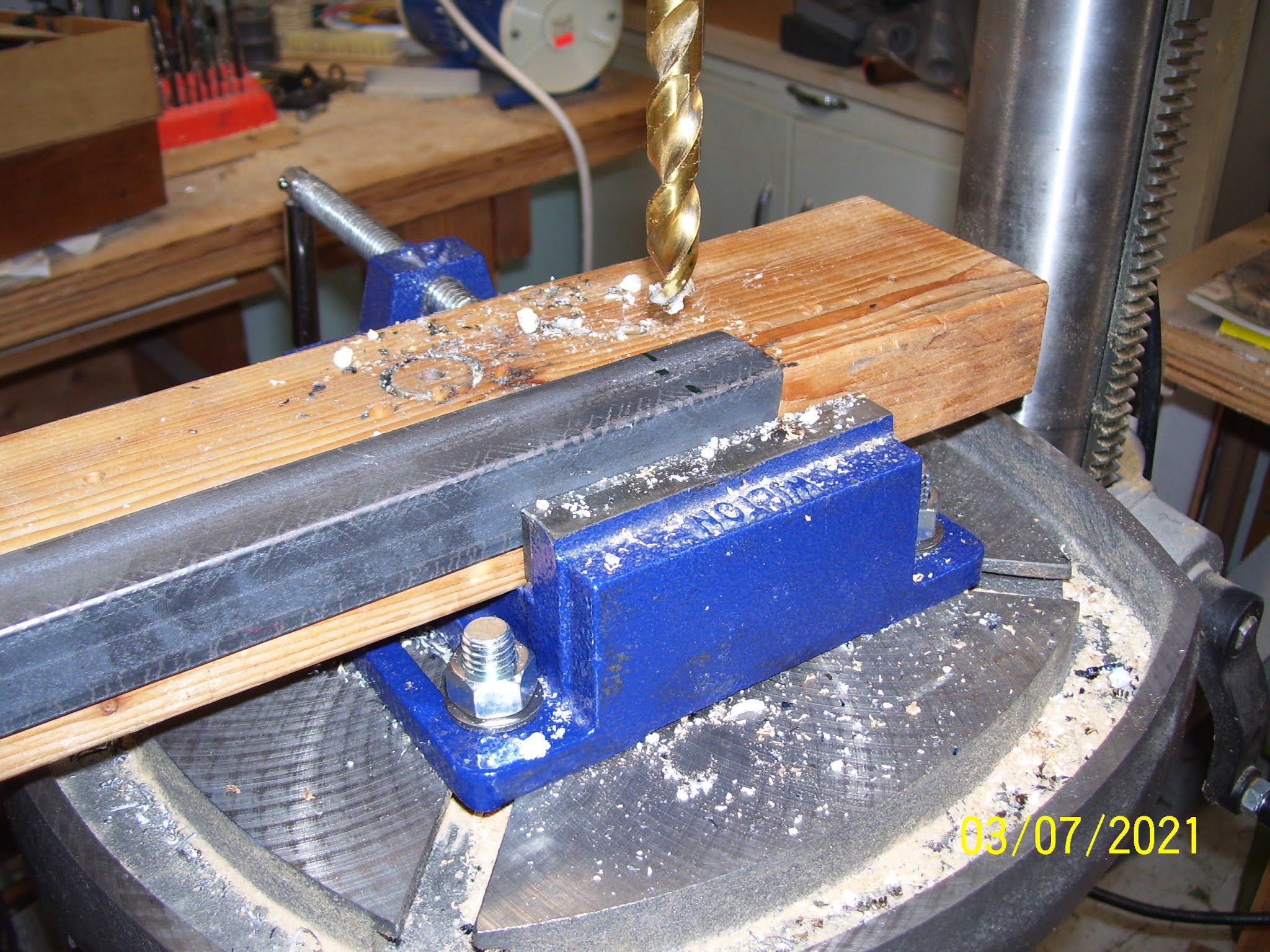


I should also mention that before all this drilling I cut the angles in half as a starting point. So each angle is currently 24 inches long. I used my sawzall with a metal cutting blade. It made quick work of that. I then used my grinder to remove any sharp burrs on the cut edge. Then, before you start drilling holes, you also have to decide how you wan tot position the angles - with the perpendicular flanges faced outward or inward. from the mounting surfaces. In the pics you can see I chose to have them placed inboard - no real reason, but you have to decide how you want to position them so you know which side to drill the mounting holes for the bolts.

After the first 4 holes were drilled I mounted each angle to the mounting flange of the engine stand for a trial fit. 


After this trial fitting, I discovered that the AN8-11A bolts I ordered were just a little short for the 3/8 inch thick mounting flange and the 1/8 inch thick angle. SO I ordered some An8-12A and 13A bolts that arrived today that should fit the assembly a bit better. The issue with the hardware is the length. It cannot be longer the thickness of the spider lugs and the angles. I was concerned about this when mounting the bolt so that bolt threads are facing the firewall and threatening to get a little to close to it after they are tightened down. After reviewing a few posts from other builders I saw that this is much less of an issue if you mount the bolt so that the head is on the side closest to the firewall, and the threads and  bolt shank are on the opposite side and never at risk for puncturing the firewall. 

The last pic is the 3/4 inch wrenches I used to mount the bolts. When the weather improves again I will replace the AN8-11A bolts with the longer ones, and begin the process of reducing the size of each angle to its final size when I fit the other end of them to the  spiders.


Sunday, February 7, 2021

Making a Rotisserie for the Fuselage - Part 3

As part of my effort to re-engage in building my wings, I needed to order some new Primer. My old AKZO Nobel 2 part epoxy primer, although proven by me to work well enough enough at 7 years plus older than the shelf life date on the cans, is now so old and unused that I have decided not to continue to try to work with it. So I ordered a new can of catalyst and primer - expensive stuff. Picked up a tip from a fellow builder to get 8 empty quart sized paint cans from HD airplane supply and pour the contents into each of these smaller cans to make it easier to pour, store, and prepare. Having had real experience with this in the past by spilling it on the floor while trying to pour in in the small mixing cups,  and knowing precisely how bad smelling and toxic the catalyst is, I think this is a very good idea.

In addition to the primer, I decided I also needed some additional AN bolt hardware to finish the  rotisserie. Each spider leg has two holes in either end of it, and each of those are between 7/16 to 1/2 inch wide on average. With the hole on one end being addressed by the AN3 hardware and wood spacers, etc., I needed to figure out how to attach the other end to the angle. This other hole would normally contain the metric bolts that came with the engine stand. I need to use this other predrilled hole and drill an additional hole somewhere near the middle of each spider to provide the necessary holes to attach the angle iron to the spider.  You need to drill the extra hole in the middle to ensure that the angle is secured in at least two places on the spider arm, so that it cannot rotate out of position.

The next problem is figuring out what length bolts I should use for the remaining holes, to ensure they are short enough so that they do not come into contact with the firewall after attaching each angle to the spider on one end and the center mounting plate on the other. Each of the lugs on the spiders allows for about 1 and 1/2 inches clearance from the firewall. Unfortunately, the metric bolts that come with the engine stand are about 1 1/4 inches long after being inserted into the hole in the spider, so that leaves a very uncomfortable 1/4 inch of free space between the firewall and the angle iron adn spider bar - This is NOT good enough for me. 

SO I need to get shorter length bolts and corresponding hardware. That means I needed to go back to the suppliers and the conversion/identification charts to figure out which AN hardware I should get. My decision, based on measuring hole diameters and lengths and grip requirements and such, was the following:

For the other big hole in the spider and the 1/8 inch thick angle iron that will be attached to it, I decided on either AN7-11A or AN8-11A, since the holes sizes seem to hover somewhere in the vicinity of either one. I order both, and I will see which one gives the better. tighter fit. After I figure that out, I will know what size hole I have to drill in the angle iron.

For the second hole in the middle of each spider to lock the angle iron in place like others seem to have done, I decided to use AN3-7A bolts. Both of these bolt choices should leave at least a half inch or more of clearance from the firewall after being bolted together. That I think I can live with. I also ordered the required nuts and washers for all bolts. The AN7 and AN8 bolts get AN960-716, 726L, 816, and 816L washers, and AN365-720A and AN365-820A, or MS21044N8 lock nuts. The AN3 bolts use the same nuts I already received from Straight Flight, so I think I already have enough of those to use on the shorter AN3 bolts as well.  

I also ordered some hardware that I mentioned long ago in my blog when working on the fuel tanks. I ordered about 50 NAS1352-08-8P cad-plated socket head cap screws to replace the fuel tank access plate screws provided by Vans - AN515-8R8. I have seen too many posts from builders stating how difficult it is to remove Phillips head screws from the access plates of the fuel tanks when you need to service or replace the fuel senders or the fuel line or return attachment hardware or connections. There are 17 of these screws for each fuel tank, so you only need 34, but I always need extras, so I ordered a few extras. Somebody on VAF also asked if a washer would be needed for these cap screws, since their grip width of the head is not as wide as the AN515 screw heads. I am glad he asked that question, as I would never even thought about that. The washer for the cap screw is AN960-8 or AN960-8L for the thin version. I ordered 50 of each of those as well.

My order was shipped from Spruce's Georgia location, and at first I found this to be strange, since most western-based orders are processed by the Southern California location. But on second thought, with southern California's horrible pandemic situation, I am actually relieved that my order came from somewhere else. It also wised me up a bit about hardware orders or any orders for that matter that I will be needing for supplies, parts etc., as I re-engage. I need to be careful about where these are coming from, and develop a process to clean them carefully when I receive them - just to be safe. It is supposed to be here in a couple of days, and then I will resume the work on the rotisserie.

Coming - up - I need to degrease/remove the oil coating from my QB fuse, which now has a layer of fine abrasive forest fire ash particles on it from all the fires in the state this past summer and fall. I have stupidly left this unattended ever since it was delivered to me in 2018. This stuff even penetrated inside the house, so everything is covered with it, inside and out. So this is long overdue, and needs some serious attention. Also coming soon is the upgraded electrical service and heat into my garage. Enough is enough, and I really need to address my hostile building environment this year if I ever want to finish this project. I will also need to order more Proseal and some special formulated sealant for the fuel tank access plates. More on that later.


Sunday, January 31, 2021

Making a Rotisserie for the Fuselage - Part 1

 While I continue to review my parts situation for the wings to prepare to place a new order with Vans and other vendors, I caught an ad from Harbor Freight a couple of weeks ago for a 1,000 pound capacity Engine Stand that many builders have used as a rotating rotisserie for the RV-8 fuselage. The rotisserie is mainly used as a back-saving tool while assembling many of the parts and components of the cockpit interior and floor panels. It may also come in very handy if I decide to paint my own airplane, which I am once again heavily considering. I have a new idea for a paint job for this airplane that so far seems to be pretty unique. That's all that I am willing to share about that for now, in the interest of keeping it as unique as possible. :)

 I have reviewed numerous other build logs from other builders, but I still rely most heavily on the log from Steve Riffe, who has been flying his airplane now for about 3.5 years or so. He used the same engine stand for his fuselage, and he also learned about this from other builders. While looking at pics of his engine stand, I noticed that the frame design is different, because I think they change designs every so often for the same product. Changes are mainly with how the wheels are attached to the base, and how the support bracket that attaches to the vertical bar and the horizontal bar to add support to that critical area is constructed. I purchased the stand brand new from HF for under $70.00. It requires minor assembly, but the parts are heavy, so be prepared.

Since the QB fuse as delivered by VANs only weights between 150-200 pounds max (if that), this 1,000 lb. stand is more than sufficient for the job. the main issue is the length of the fuse, which creates a long moment (Remember your weight and balance training - WxA=M). This means that if the tail is unsupported while the front is suspended by the engine stand, all of that weight along the entire length of the fuselage has to be supported by the stand and its attach points to the firewall. The idea is to use the stand in the front, and lay the tail down on a small saw horse, milk carton, or custom-built wood stand as needed, so the weight that must be supported by the stand itself is minimized as much as possible. I also wanted this particular stand instead of other available models because it has the additional lateral wheel bracket in the front, which helps provide some additional lateral stability to the fuselage when mounted on the stand. 

The main problem I encountered when considering this, is a lack of  a detailed information about the hardware used. So I will attempt to solve that problem. As always, keep in mind that I make no claim of suitability or guarantee that your results will match mine, so you are responsible for determining if thi will work for you or not. YMMV. 

Here is a pic of the assembled HF Engine stand, ready to be converted to a fuselage stand:


I used my yellow angle finder tool to determine the angle of the vertical post and the base support leg, since the angle is not 90 degrees. Most folks remove the front wheels of the stand to bring the vertical post closer to 90 degrees, so that it aligns vertically with the firewall when mounted to the stand. This needs to be done so that it does not put any undo stress on the firewall when mounted to the stand, which would be very bad. 

Since the wheel brackets on mine seem to be a little higher than others, I may need to compensate for that a little by raising the front up a little more with wood shims, but time will tell on that. The angle I measured is almost exactly 5 degrees, although in the above pic it  appears to be much greater than that. 


The rotating bracket that comes with the stand that the firewall will be mounted to comes with 4 "spider leg" attachments that are normally used for running heavy bolts through the spacers or lugs at one end of each arm that then screw into the back of a car engine. 2 of the arms are shown in the pic below.


The mounting plate has slotted holes to allow the location of the spiders to be positioned so that they match the mounting holes on the engine. Unfortunately we have to change this up a bit to modify this assembly for use with the fuselage, but it is not too difficult to do. I will still use the spider arms, but they will be attached to the ends of some angle iron that is cut to the correct length to act as an extension, so that the mounting plate remains near the center of the firewall, while the spiders will be bolted to the 4 holes in each corner of the engine mount holes and brackets behind the firewall, AND to the angle iron extensions. 

Similar to Steve, I decided to use AN hardware for most of the attach points for the spiders to the firewall/engine mount brackets, which have a minimum 125,000 lbs. of tensile strength, to ensure that the bracket has enough strength to stay attached to the firewall the entire time. The immediate problem that has to be overcome is that the stand comes with very large metric bolts. 

Unfortunately, when Vans builds the QB fuselage, all the engine mount holes are only pre-drilled to 3/16ths of  an inch, which is the smallest AN bolt diameter you can obtain before having to revert to screws. Furthermore, if you read ahead in the VAF forums and the Vans instructions for the Fuselage assembly, you will find that they say NOT to drill out those engine mount holes until you have the actual engine mount in your possession, so you can use it as a drill guide. 

This is necessary because the weldments for every engine mount vary a bit from one to the other, so you are not supposed to up-size the bolt holes without the engine mount to ensure the holes are drilled out correctly. The engine mount bolts are 3/8 inches thick, or AN-6 I  think, so they are substantially larger than 3/16 inches. Since I do not have my engine mount yet, I did not want to upsize the holes, but I was also concerned that this would mean that only AN3 sized-hardware would be attached to each existing hole. 

Steve informed me that he did exactly that - used the AN3 bolts in each corner, and he had no issues with anything while using the rotisserie. I also contacted Vans about this, and they said it would probably be OK to upsize the holes about half way in between the current size and the final size, since most engine mount holes may only vary by a max of 1/8 of an inch or less from each other. They also thought that AN 3 bolts would be "a little light. 

Other builders decided to drill up to AN 4 bolt holes, and I think I saw others yet again that drilled them out the final AN 6 size. At the end of the day, I decided to stay with the AN3 bolts to avoid upsizing the bolt holes without the engine mount. Steve said he had no issues, and the reality is that all the other bolts used in the assembly are the same beefy ones provided with the engine mount. So I think his will be fine.

With that decided, there is another  problem that I felt I needed to solve. While the AN 3 bolts will precisely fit in the predrilled holes in the firewall, the predrilled holes in each spider leg are extremely large, I was concerned about running such a small sized bolt through the large hole in the spacer lug in the spider leg, without having some kind of additional support for the bolt shank. So, similar to another builder (I am sorry I did not capture his build log) I decided to cut a wood dowel to the correct length to fit inside the lug or extension, and insert it into the larger hole in each spider. It turns out that a 5/8 inch dowel from HD aircraft supply works very nicely here, at least as far as the fit into the spider lug is concerned. I measured and then cut the 5/8 inch dowel into 4 separate 1 1/2 inch long inserts using my bandsaw, as shown below.


After you have cut the spacers, the next step is to take a rubber mallet and tap them into "submission" into each lug hole:


IT turns out to be a very nice "press" fit. Each dowel is only long enough to reach the base of the lug where it is welded to the spider arm. The dowel will not fit all the way to the bottom of the arm because the holes from the lug that they welded to the top of the bar are not the same size. The holes in the bar are a little smaller, so they will stop at that point.

Now for the hard part. The next step was to drill out  a 3/16 inch hole in the center of each dowel.  I won't lie, for me this turned out to be a bit of a nightmare, because I found out that dowels do not like to allow a drill bit to follow a straight path from one end to the other. All of initial holes I drilled ended up being misaligned, and I ended up having to continue "custom" drilling each hole in the dowels to "force" them to run more or less from center to center. Basically that means I had to enlarge the hole a bit by using a drill bit to gouge out the holes. 

I also needed to create a few replacement dowels, because the hole drilling went so badly that I could not salvage the insert. I tried using my massive large drill press first. It vibrates badly, and I cannot figure out how to secure things very well to the stupid drill table. After a few attempts with the drill press, I gave up and decided to try it free hand.

First I tried to put it in my table vise vertically - same result. the drill bit would meet the wood and instantly take its own undesirable path to the other end of the dowel.


 Then I tried putting them flat on a drill board and clamping then down with bar clamps:


I originally started with a #40 drill bit, then followed with a #30, followed by a 3/16th inch drill bit for final drilling. This also did not work very well for me. The hole on one end starts out centered, and the hole in the opposite end is completely uncentered and off to one side. I even used my center punch to try to start the hole in the exact center of each dowel, and this did not help much either.


Here are the results of several attempts. This side looks OK:


But not this side:


Example of extra gouging:

About as badly aligned as it can get:

At the end of it all I decided to put my 3/16 inch drill bit into my cordless drill, and after drilling the initial hole, I manually "corrected" any offset in each hole by gouging it out with the drill as best I could.  Then I ran each bolt through the holes to check for centering. it does not need to be absolutely perfect, but I wanted it as close as possible to avoid and excess stress on any of the bolts, or the points where they are attached.  Here are the end results:


Here is an example, taken before I made and drilled the dowel inserts, of the upper left corner of the firewall/engine mount hole, and how the spiders are attached to it. The lower end will be attached to the angle iron:


And here is pic that l also do not see in anyone's build log - how the bolt attachment appears on the inside of the engine mount hole, taken from the rear of the firewall, where the bolt protrudes through the predrilled hole from the factory:


More on the remaining assembly in the next post..

Monday, October 22, 2018

Fuselage damage from shipping?

About 2 days after the fuselage arrived, I started doing the inventory of all the parts, and finding places to put everything by rearranging my shelves by consolidating my remaining wing parts together to make room for all the new fuselage parts. I also started a much more thorough review the of the entire fuselage to look for any signs of damage. Unfortunately I did find a few things with the firewall that concerned me. the first was several splatters of something that dripped on my firewall that does not want to come off.

And then I found this in the bottom corner:
Obviously something had pushed on the bottom front corner of the firewall, and this in turn caused a crease up above where the bottom support angle for the floor support was located. It only creased the firewall in that area, so it was not cracked, but it causes me some concern because this area may tend to fatigue sooner than it should as a result of this. I called Vans and sent multiple pics and they ended up saying that it was "cosmetic" and not a concern. I have an email from them just in case this pans out differently. There is really no way for me to straighten any of this, and I might end up making it worse if I were to even try. I was disappointed, because just about everything else on the new fuse looks absolutely fantastic. 
When you have done this long enough, you come to realize that shipping damage is fact of life. The thing you must evaluate is something may turn into a life threatening situation for you or your passengers. Vans pointed out that the crease and the dent are in an rea that I basically a void where nothing much is going on except to provide a frame for the outer skin to wrap around the side and underneath to make up the bottom of the fuselage skin. All of the actual support structure begins just above this area, where the bottom and side angles create the structure that supports the weldments for each of the 4 engine mount bolts that hold the engine mount to the firewall. SO as long as this damage confines itself to the area it is located in now, there are no problems, I will however need to keep watching this, because if any cracking starts to form that will migrate to the upper areas of the firewall or the rivets in this area, then I have an issue that must be dealt with.

Here is another area I found, which looked like a crack in the weldment for the cross member. Vans told me that sometimes the powder coat surface will show some signs of surface cracking, but that's all that this is. They told me to take light sand paper and sand own the area to see if the crack disappears, or if it truly goes all the way to the metal. IN my case, the crack disappeared, so that was a relief. 
There was this "galling" of the landing gear in certain areas as shown below. Vans told me that this is common and is a result of sand blasting that is performed in this area of the metal for a number of reasons. It just looked strange under the powder coat. SO this one I have to take their word for it. My take on this is that as long as I treat the plane properly and do not subject anything to super hard or out of control landings, then the gear should be just fine.
And finally some pics of everything put away on shelves, including the very large curved top rear outer skin:


Pics of the QB Fuselage arrival on 9-22-18

As promised, here is a picture sequence of the arrival of my QB RV-8 fuselage. Basically what came in the tuck was the fuselage in about 75% completed state, a small box of remaining parts to assemble, and the Van's stock spring steel landing gear. A lot of builders are opting for aluminum landing gear made by a company called Grove, mostly because they seem to provide similar service but are about 20 lbs lighter than the stock gear. For now I am OK with the stock gear since most of my mission for the airplane consists of transporting only me, myself, and I where I want to go. Lots of powder coated parts for the rudder pedals and control stick linkage, etc., as well as parts for the seat floors, upper fuse skins and bulkheads, seats and seat backs, and baggage area parts.

Step 1, the custom truck arrives. The trash cans on the right side had to be placed in front of my house to prevent others from taking up parking space. I live across from school property with baseball, football, and soccer fields, and the fall is very busy with little league games being played on these fields across the street. SO naturally cars like to park along the sidewalk in front of my house. Well, today I needed the space for the truck, so I had to take precautions by tying up some orange tape between the two cans and setting them out in the street to keep others from taking up the space for the truck. When the truck arrived, the cans were placed on the yard on the right.

Next, the doors were opened, exposing the aft side of my fuselage on the bottom, and another RV-7 fuselage on top and further inboard in the trailer. The white scaffolding on top is part of the custom crane boom that allows one to lift the fuselage completely out of the trailer without the need for a forklift.
We had to move mu fuse out from under the RV-7 fuse a bit to allow the block and tackle assembly to be placed bear the Center of gravity of the fuselage, so that when it is lifted it tends to balance on the crane without being to tail or nose heavy. Funny, W&B for this was just as important as it is when you are flying. It was interesting to see where the balance point of the 16 foot long fuselage. When is it all finished, with an engine and the tail section installed, it will be about 21 feet long. The balanced point ended up being just forward of the steel seat back support cross member that separates the front and back seat passenger compartments. The front straps from the boom assembly were strapped around two plywood extensions  that run through the center section wing spar where the wings will eventually attach to the fuselage. The rear strap was wrapped underneath the rear of the main cabin and attached to the boom. then the crane hook was attached to the assembly  and it was time to lift it up and out of the trailer.

 Chapter member Scott Barkley was there to help me with the off load. The gentleman above is the truck driver. That's about all it took - the three of us - to off load the whole thing. It only took about 15 minutes or so. Next the crane boom is extended and the block assembly is being prepared.
Next, Scott is guiding the tail as the crane lifts the fuse and starts walking out of the trailer doors. Mike Rettig loaned me his specialized cart that he built to support his tail section of his RV-10. Turns out that it supports my entire RV-8 fuselage quite nicely as well. Thanks Mike!!!!!!!
And here is the boom assembly after having been moved out onto the extensions:

And finally it was lowered onto the dolly and the crane was disconnected. Now all we had to do was wheel it up to the garage. Worked like a charm with no issues whatsoever.

Scott Barkley after a job well done! Many thanks Scott for your assistance with this. 
And the next series of pics is where the unpacking begins. You would not believe the amount of packing paper that was stuffed into the fuselage, not to mention how everything was packed inside the fuse as well as inside the additional parts box. It begins with the push/pull tube for the elevator and the hinge material for the cowling that will be attached after I get the finishing kit. With all the trials and tribulations I mentioned in my previous post, I will say that Vans is definitely master at figuring out how to pack things in small spaces. Enjoy the sequence:


And finally the contents of the parts box. It also comes with a large box of hardware, and two trashcans full of packing paper!