
Been a while since I last posted. Snowblower repairs, bad weather, and a wonderful cold have kept me at bay for a while on the project. Finishing the scarf joint turned out to be royal pain in the butt. I thought I had finished the joint, had a pretty good fit between the wing skin edges and the fuel tank skin edge, and then I final sanded everything with 320 grit aluminum oxide sand paper to remove the deep scratches. Then I took both wing skins off of the frame set all the remaining dimples with my squeezer, masked off the sanded areas of the wing skins where I formed the scarf joint, and primed them all with NAPA 7220 self etching primer.
Then I reapplied both wing skins to the frame to check the fit, since this was the first time that the dimples were added to that entire area. To my utter disappointment, the skins looked like they had not even been touched. The edges stuck out like sore thumb. My friend Mike had warned me about this a while back, but I thought that was because of the skin edges not being slightly bent, which I had already addressed. However, it became apparent real fast that the newly dimpled skins and the added primer were both causing the skins not to ft very well against the wing spar flange.
SO I called Vans about this. they said that you really can't judge how they will go together until you actually rivet them to the spar, and not to worry about it too much. Well, I decided to try to alleviate at least some of this ill-fitting issue, so I took off the inner skin, noticed that the edges of the skin were quite thin, but that the rest of the metal moving away from the edges still seemed to be a bit thick - indicating that I had not removed enough metal on the inner portions of the wing skin. So out came the file one more time. This time I focused ONLY on the inner portion of the skin, staying away from the edges as much as possible.
Then I re-sanded the deep scratches from the file and re-primed the small 1 inch square area that I was working on. Then I rechecked the fit and decided that enough was enough, and it was time to move on. I think I pretty much realized at that point that it was the dimples and how they were fitting into the countersunk hole of the spar flange, that as causing the fit problem, even though the hole has been countersunk a little bit more than flush per Van's instructions.
When this areas gets riveted to the spar that metal will be forced into the spar flange hole and hopefully will smash down a bit more with the force from the rivet gun. If I don't like the fit after that, I can drill the rivets out and figure something else out. OH - but wait - by the time you get to this joint in the wing for riveting, you have already done the rest of the holes in the skin, because per the plans you save this lovely area for last. So I'll be damned if I am going to rivet everything else just to find that this area is still not seating properly. Others don't seem to have problems with any of this, so why the hell am I?
Time to move on. The scarf joint is as done as it is going to get. I am pretty certain that all that I will get for my efforts on this is a cracking wing skin in this very area once I start flying. If I do, you can bet that I will be asking myself why I even bothered with this stupid scarf joint - which some builders have also decided not to do, since it is "only cosmetic" per Vans.
I re-inspected the state of the leading edge assembly after my near disastrous and stupid attempt to force it off of the wing spar with the fuel tank mounted next to it. (See my Stupidity label to find the post). I tweaked the rear flange of the inboard 408 rib a bit more with the handseamer, and I checked for cracks or fatigue, and did not see any evidence of that. I removed the fuel tank assembly from the wing spar and remounted the LE assembly, all the while having flashbacks to my stupidity from before. I re-secured the LE assembly to the wing spar with clecoes and then added the fuel tank assembly. That's when I got my next head scratching moment - when the edge of the fuel tank skin and the LE skin did not line up correctly.
Initially I had a situation where there was no gap at the very tip of the LE and the fuel tank skins, but as you went further aft, this turned into at least a 3/64s inch gap. WOW! I thought I had everything here all matched up nice and neat - so once again I foud myself asking what the ^&*O&%$^! Obviously this was some sort of angular issue between the wing frame and the LE and Fuel tank assemblies, which I had verified long ago were butting up to each other with no gap whatsoever - so I knew that something just "wasn't right."
So I'll cut to the chase. There were two things that found that I needed to do. The first is a long standing problem that I have had ever since I put the frames on the wing stands. I used a hydraulic jack to support the center of the wing frame, which does sag under the weight of the wing assembly when mounted on the stands at both ends. I thought that this would be a great method - but found out long ago that these jacks do NOT hold their pressure forever, and they start to slip. As a result, I have had to continuously reapply pressure to the jack to lift the center section to keep everything aligned.
This time I wanted to be sure to recheck the "level" state of the frame by using a fish line strung across the rivet holes of the spar flange and held in place by two clecoes - one at each end. Then you apply the pressure from the jack until the fish line cuts through all the rivet holes evenly. Works great, and I found that I needed to apply more pressure once again to level everything out. The only problem with this is that to do it correctly you need to remove the wing skins from the frame. I did all this in warm weather, before the cold snap hit over the past couple of days. Seemed to level everything out again.
Today is the first day since I got sick that I have been able to go out and check on things in the garage. What I found this time was even more shocking. This time the gap between the LE and fuel tank skins was consistent from top to bottom, and was quite large on both sides. So once again I am asking what the ^&%^%#%$!. I rechecked the jack, but after leveling the center again I still had this huge gap.
The Le had been firmly reattached to the wing spar several days ago, so it was not moving. That meant that something was up with the fuel tank for some reason. When I put both assemblies back on the wing spar, the fuel tank was butted up against the LE skin and then I clecoed the inboard-most holes in the baffle and Z bracket on that end. Then I put #30 clecoes back in each screw hole through the nut plates, just as I had done many times before. None of the other fuel tank ribs, including the outboard-most rib, were clecoed, because at the time I did not think I had access to those holes since the LE an fuel tank are now butted up against each other.
So while scratching my head about this latest quandary, I came up with a plan, based on the only thing I could think of that was causing this gap problem - the clecoes I used to attach the fuel tank assembly to the spar were not allowing the skins to line up correctly for some weird reason. So I came up with a brilliant idea - make absolutely sure that the center of the wing frame was level (again), remove all the fuel tank attach clecoes, slide the fuel tank assembly over till the skins are snugged up against each other, and re-clecoe the fuel tank to the spar again. Then check the fit and go from there. I was skeptical about this whole thing, because I thought that the rib to Z bracket holes would now be out of alignment after sliding the skins together to "make" them fit. I found myself asking - "did I really mess up the whole fitting process and drilled the wrong holes in the wrong places, and that is what is causing all this?" Could I really be that stupid - again?
However, much to my surprise, after I re-clecoed the inboard rib to the inboard Z bracket, and then started carefully applying #30 clecoes to the screw holes through the nut plates again, the skins magically all lined up like they were supposed to, and they stayed that way as I added each cleco. Thank goodness for that is all I can say. Then I saw that I could still apply the clecoes to the outboard fuel tank rib and Z bracket through the access panel opening of the LE. And the skins stayed flush together after I did that. How bazaar is that!
The only thing that I can conclude from this is that I think there was some misalignment of the inboard and outboard ribs when the rest of the fuel tank assembly was removed to match drill the baffle to Z bracket holes for the remaining fuel tank ribs. It could also be that the sagging center section of the frame, combined with some slight shifting of the screw hole clecoes, may have caused the misalignment occur. Putting #30 clecoes in the holes intended for the screws in the fuel tank skin, which have yet to be dimpled, is a bit out of the ordinary. Normally you put clecoes through matching holes in two or more pieces of metal.
However, in this case, until the fuel tank skin holes are final drilled to size for a #8 screw, and dimpled, you are inserting a clecoe into a hole in a flat skin, and then in turn the rest of the cleco must extend further than normal, all the way into the end of the nut plate on the inside of the spar flange. This results in a clecoe that is under higher spring tension than usual, since it has to be extended more than usual, and the flat skins are then being pulled slightly into the large countersunk hole in the wing spar flange, causing some uneven tension on the fuel tanks skin. When you combine all this with an unsupported center section of the wing frame, it is not hard to see how things might not line up correctly.
The lesson learned from this is to make sure that parts that you know are supposed to fit together are actually mated that way first, and THEN you cleco everything in place - NOT the other way around - i.e. clecoe everything and then check the fit. Clecoes that are inserted into places where they may be allowed to shift or distort the assembly a little (flat skin screw holes into countersunk holes nut plates for example), can cause such a mis-alignment of closely fitting parts like skins. The second lesson learned here is that I need to replace the STUPID hydraulic jacks with a 3/8 inch threaded shaft with a small wood support on one end, and a large washer and nut assembly on the other end, inserted into a solid wood base with a hole slightly larger than 3/8 inches for the rod to freely insert into, and adjusted so that the center section of the frame remains level ALL THE TIME! Don't use stupid hydraulic jacks unless you want to feel my pain.
So I already have one screw jack assembly from another builder, which I obviously never used, and I'll need to fabricate another one for the other wing stand. That is my mission for tomorrow. SO in short I have been on a bit of wild ride ever since the time came to remove the LE from the frame to start working on the fuel tank assembly on the wing spar. It's been one wild thing after another ever since.
The last thing for tonight is that I finally have the LE back on the wing frame, which is the point that I was trying to get back to ever since this latest round of madness began. I needed to get the LE back on the frame one last time for it is final-assembled so that I can get down to business and make those final decisions about cut lines and new rivet holes and locations for nut plate and screw holes, all in preparation for the big "cut your LE to pieces" exercise. I worked out some final measurements tonight and will elaborate more on all that in my next post. I am very close to being ready to make the cut in the LE skin once these measurements are finalized.
Showing posts with label WIng Stand. Show all posts
Showing posts with label WIng Stand. Show all posts
Wednesday, November 8, 2017

Saturday, May 24, 2014
Finally done setting up the wing stands
All 4 bottom brackets are now bolted in place, and I have all 4 plumb bobs mounted from the next cleco inboard from the one on all 4 end ribs. I chose to suspend the fish line and plumb bob from this location so that I could keep all clecoes attached to the end ribs and allow the fish line to swing freely. I will use my square to obtain the necessary measurements to determine if I need to adjust the wing for any twist. I put gorilla tape on all bracket surfaces,especially the ones that will come into contact with aluminum and steel. A nifty chart I got from Cleaveland tools along time ago shows the compatibility (or lack thereof) of various metals. Aluminum alloy attach brackets are NOT compatible with steel, and will start to react/corrode if left in contact with each other for extended periods of time.The layer of tape between the 2 surfaces should prevent that from happening.
You can't see the steel bracket too well in this first pic, which shows the the two inboard ends of each wing clamped at the rear spar attach point. These are the ends that will be adjusted if there is any twist in the wing. You can also see the two plumb bobs suspended from the clecos at the main spar:
 Next are the pics of the left and right wing outboard attach points with plumb bobs suspended.


Wow. Now maybe I can start drilling wing skins again for a change. I'm tired of drilling holes in 1/4 inch thick steel. Next time I'll have some pics of a recent visit to a hangar at KFTG last week where our EAA chapter visited 2 RV-7A projects that are very close to completion. John Tetter and Lyn Langer's aircraft are looking great, and I took a lot of pics from my camera phone of everything from fuel systems to landing light and fuel tank assemblies and fittings and more. Lyn also had a backup alternator on his engine. Lyn's engine is also one that I am considering to purchase from Superior in Texas, so I spent quite a bit of time examining that.
Recent wind and weather events here in Colorado also have me contemplating my decision to build a nose wheel or tailwheel aircraft. More later.
You can't see the steel bracket too well in this first pic, which shows the the two inboard ends of each wing clamped at the rear spar attach point. These are the ends that will be adjusted if there is any twist in the wing. You can also see the two plumb bobs suspended from the clecos at the main spar:
Wow. Now maybe I can start drilling wing skins again for a change. I'm tired of drilling holes in 1/4 inch thick steel. Next time I'll have some pics of a recent visit to a hangar at KFTG last week where our EAA chapter visited 2 RV-7A projects that are very close to completion. John Tetter and Lyn Langer's aircraft are looking great, and I took a lot of pics from my camera phone of everything from fuel systems to landing light and fuel tank assemblies and fittings and more. Lyn also had a backup alternator on his engine. Lyn's engine is also one that I am considering to purchase from Superior in Texas, so I spent quite a bit of time examining that.
Recent wind and weather events here in Colorado also have me contemplating my decision to build a nose wheel or tailwheel aircraft. More later.
Tuesday, May 20, 2014
RIght WIng outboard lower wing stand bracket completed
Same measuring, cutting, grinding, fitting, drilling, as the left wing, and the lower bracket for the right wing is done. Everything fit just as well as with the other one, so am pleased with the way this one turned out as well. 4 more lousy holes to drill in the other stand for each wing to install the other brackets. The other ones will be clamped into place against the rear spar mounting flange after checking both sides for any twist.
Here is the shot of the right wing outboard bracket wide shot:
 And the close up:
 I had to grind down about 1/16 of an inch of the inboard section of the steel bracket as it was just a bit too close to the rib. All this means is that my measurements for the placement of each wing stand were a bit different between the left and right wing stands. Not a big deal. The 3/16 inch hole for the tolling hole in the rib was spot on, so my exhaustive approach to accurately transferring measurements from one part to another are paying off. I need to buy some more 2 inch steel angle to fabricate the remaining two brackets, and then I can get back to drilling holes in wing skins - FINALLY! These wings ain't goin' anywhere any time soon.
Here is the shot of the right wing outboard bracket wide shot:
Sunday, May 18, 2014
More about wing stand bottom support brackets......much, much more......
IN my previous post I mentioned that I was going to use clamps to avoid measuring and drilling more bolt holes in my wing stands. The Vans plans do not elaborate on the bottom support brackets, nor do they show a detailed inset of the assembly for the bottom bracket like they do for the top ones. Well since the last blast of winter moved out of town, for some reason I changed my mind and decided to proceed with all the necessary cutting, drilling, fitting, and leveling of the bottom support brackets. Call me a sucker for punishment I guess.
Part of the reason for doing this is to document it for other builders. I could find pictures from other build logs showing how others have done this, but I never see any details written about how the did it. That would leave one to believe that the procedure may be so simple that it is obvious, but I say that could not be further from the truth.
For the bottom brackets on the tip end of the wing, you have to deal with the proximity or distance of the ribs and skins to the lower angle bracket, the overhanging skins from the tip rib (about 1/2 inch), and ensure that the wings are mounted on the stands in such a way that the the lower tip bracket can be mounted to the tip rib without interfering with the overhanging wing skin at the trailing edge of the had to reverse the right wing on my stand because of this.
Anyway, a whole lot of tools and measurements and drill bit changes and fitting and cutting and so on later, I managed to get the bottom bracket fitted exactly the way that I wanted it. The only less-than-desirable thing was the 3/16th inch #10 hardware that I had to pick up from the specialty hardware store in my area to attach the angle to the tip rib, since the big box stores don't really carry bolts in this size at all. I ended up getting some screws that are threaded all the way to the pan head, and I really need something similar to the tank attach bracket bolts, but they are not quite long enough for the job.
ON to the pics.I started by using my top brackets as a template for the length of each bottom bracket. I measured and cut them from some existing 2 inch steel angle that I still had lying around. Note that I am using 2 inch angle on the bottom brackets, which is necessary for me because of the 1.5 inch angle I used for top, combined with the 2 inch short angle pieces that attach to the rib and set over the top of each top support bracket. I did this to add the necessary gap between the extended skins that exceed the flange of the final rib to act as the attach points for each wing tip. I used bar clamps to secure the angle to the bottom of the wing stand,and quickly discovered how close to the bottom wing skin the angle would come (less than 1/8 inch.) I also had to check it for level since I was going to drill another bolt hole to attach the angle to wing stand. It all had to line up correctly to avoid interfering in a number of different ways.
I measure and drilled the 1/4 inch hole in the angle bracket as shown below:
 This hole is 2 inches in from the end, which should center it along the 4 inch side of the 2x4 steel post. the Perhaps I should have started with the step where I drew the reference line across the top of the angle after leveling it against the post and positioning it the way I wanted it. Here is both the inside bolt hole that was transferred by an ultra fine sharpee pen from the hole drilled in the angle. This made marking the first bolt hole rather simple.
 I then used my straight edge and clamped it along the reference line so I could use my tape measure to measure the line from the top of the post down,which is the most common area to use to ensure the measurements are transferred accurately over to the other side of the post.
 THis next pic shows many things. First is the line transferred to the outer side of the stand, and the bolt hole and bolt that were ultimately drilled and secured along with the angle to the post. I should also point out that I ground down the edges of the steel angle and smoothed them on my scotch brite wheel. I don't want any of the heavy metal marring up the airplane parts so this was essential.
Next is shows how closely this angle comes to the top and bottom skins, and how level it aligns with the rear spar and rear rib flange of the tip rib. It also shows the sharpee outline of the small aluminum angle I used as the attach angle to the rib. It mounts to the steel angle and then also to the forming hole in the rib. It also shows the level on top to ensure that everything was in alignment.
 Here is another view
 For the attach angle I used some scrap 1.5 inch aluminum angle from HD aviation department. THis is the same angle that was used as a backer plate to countersink all those pesky tank attach nut plates to the main spar. I cut it to size and smoothed it with the scotch brite wheel.
 Next came the 1/4 inch hole in the attach bracket which I just eyeballed and decided where I wanted to drill it.
 Then I transferred the mounting hole from the attach bracket to the support bracket:
 Then I removed the steel support bracket and drilled the hole. THen I was able to take a short 1/4 inch bolt and attach the two angles together.
 Then came the fun part of figuring out how to transfer the exact measurements of the location of the forming hole in the rib to the other side of the aluminum attach bracket. I removed the attach bracket, ensured the support bracket was level, and used my straight edge to mark a line on the front and back sides of the forming hole on the rib, and I extended these lines above the top marks for the attach angle so they could be seen after the attach angle was placed back on the support bracket against the rib. I then transferred the lines from the rib to the attach angle and then took the final measurement from the top edge line down. From this I had enough dimensions transferred to the attach angle so that I could drill the necessary 3/16th inch hole. I was very pleased with the alignment:
 I put a piece of gorilla tape on the back side of the attach angle so that it will not mar the side of the rib, and then used the 3/16th inch hardware to attach the angle to the rib. It fit like a glove (thankfully). I even was able to insert my arm through the next to the last lightening hole to hold a nut driver on the nut on the inside of the rib that holes the screw in place. Everything is secured nicely, and it only took me most of the day to get it all done.
 One down and one to go......
Part of the reason for doing this is to document it for other builders. I could find pictures from other build logs showing how others have done this, but I never see any details written about how the did it. That would leave one to believe that the procedure may be so simple that it is obvious, but I say that could not be further from the truth.
For the bottom brackets on the tip end of the wing, you have to deal with the proximity or distance of the ribs and skins to the lower angle bracket, the overhanging skins from the tip rib (about 1/2 inch), and ensure that the wings are mounted on the stands in such a way that the the lower tip bracket can be mounted to the tip rib without interfering with the overhanging wing skin at the trailing edge of the had to reverse the right wing on my stand because of this.
Anyway, a whole lot of tools and measurements and drill bit changes and fitting and cutting and so on later, I managed to get the bottom bracket fitted exactly the way that I wanted it. The only less-than-desirable thing was the 3/16th inch #10 hardware that I had to pick up from the specialty hardware store in my area to attach the angle to the tip rib, since the big box stores don't really carry bolts in this size at all. I ended up getting some screws that are threaded all the way to the pan head, and I really need something similar to the tank attach bracket bolts, but they are not quite long enough for the job.
ON to the pics.I started by using my top brackets as a template for the length of each bottom bracket. I measured and cut them from some existing 2 inch steel angle that I still had lying around. Note that I am using 2 inch angle on the bottom brackets, which is necessary for me because of the 1.5 inch angle I used for top, combined with the 2 inch short angle pieces that attach to the rib and set over the top of each top support bracket. I did this to add the necessary gap between the extended skins that exceed the flange of the final rib to act as the attach points for each wing tip. I used bar clamps to secure the angle to the bottom of the wing stand,and quickly discovered how close to the bottom wing skin the angle would come (less than 1/8 inch.) I also had to check it for level since I was going to drill another bolt hole to attach the angle to wing stand. It all had to line up correctly to avoid interfering in a number of different ways.
I measure and drilled the 1/4 inch hole in the angle bracket as shown below:
Next is shows how closely this angle comes to the top and bottom skins, and how level it aligns with the rear spar and rear rib flange of the tip rib. It also shows the sharpee outline of the small aluminum angle I used as the attach angle to the rib. It mounts to the steel angle and then also to the forming hole in the rib. It also shows the level on top to ensure that everything was in alignment.
Sunday, April 27, 2014
Back to the 3 "Ds" and Mounting the Wing Skins
You remember the 3 "Ds" of airplane building, don't you? Drilling, deburring, and dimpling. Today I finished deburring all of the holes in the wing walk doubler and inboard top wing skin that I match drilled yesterday. I also had to remember how to use the soldering gun to remove strips of the blue vinyl from the rivet hole lines while keeping the remainder of it on the rest of the skins as long as possible to prevent scratches.
With that all done, it was time to fit the top skins to the left wing. The inboard skin is a little tricky because you have to mount it over the top of the wing walk doubler. Actually this turned out to be fairly simple. I clecoed the top rivet holes to the main wing spar flange first, and then I slid the doubler underneath between the skin and the ribs. Everything lined up nicely and so it was easy to continue securing the sandwiched doubler to the wing frame. Vans says to cleco every fourth hole in the skin after that. Here is the inboard top skin W702 all clecoed in place with the doubler hidden underneath. The area on the right where the blue vinyl has been removed is the area where the doubler resides underneath the skin. One day I will be stepping on this area and then into the cockpit with the intent of taking my first flight.Yay! It is finally starting to look more like a wing.
Next came the W703 outboard top skin. It covers the outer 2/3 of the wing and is so it is longer than the inboard skin. Now I have to rant again about Vans piss poor instructions. They mention installing the the W702 and W703 top skins,and then make no further mention about installing the bottom skins after that. You don't figure that out until you read down further where they talk about leaving the top skins clecoed while removing only the bottom skins in preparation for installing the leading edge. Anyway, here is outboard skin clecoed in place:
 An interesting note that some may not be aware of is that the direction that the writing appears on the wing skins is the same direction of the grain of the metal. Note how the grain runs differently from the inboard to the outboard. IN fact, you can't see it, but the wing walk doubler across the first four inboard ribs is also cross grain from the inboard wing skin. This adds strength to the overall wing and does have an affect on the way that the skin will bend and twist while in flight.
And now for the next problem.... I ran out of #40 clecoes.
 Since I am building both wings at the same time, I need massive amounts of clecoes. Another lesson you learn is that the initial tool kit that you purchase will generally contain enough clecoes to complete the empennage, but you will need more for the wings and the fuselage. I will need to make some calls and send some emails tomorrow to see if I can borrow some more, but I figured I need at least 500 more clecoes, and probably even more than that. I have several builders in the area that I can ping, and then my entire EAA chapter membership, and then our Chapter Tool Officer, so I should be able to scrounge enough without having to buy brand new ones.
Here is a view of the bottom of the wing with both top skins on:
 Next is the W702 inboard top skin for the right wing on the bench with its wing walk doubler positioned underneath. Unfortunately, I need more clecoes before I can match drill these holes. I also made the mistake of keeping my bottom wing skins on my shelf, and now there is less room to maneuver with a ladder to get them down, but I will manage.

 And then finally I just could not resist this. I have had my leading edge clecoed together in its jig for a very long time, Now that the wing assembly is in progress, I wanted to see what it looked like on the wing, so I temporarily mounted it on the spar just for kicks. Still alot of prep work to do before the LE goes on permanently, but hopefully this will be done in a few weeks. The "chunk" of the wing that is missing from this pic is the spot where the LE fuel tanks will go. They will hold 20 gallons of fuel per tank. Yup, looks like s great big Hershey bar, but it is a well proven and tested design that will suit my needs just fine.
 Think Saturday Night Live starring Christopher Walken years ago when you read this next line:
"I gotta have more clecoes!"
With that all done, it was time to fit the top skins to the left wing. The inboard skin is a little tricky because you have to mount it over the top of the wing walk doubler. Actually this turned out to be fairly simple. I clecoed the top rivet holes to the main wing spar flange first, and then I slid the doubler underneath between the skin and the ribs. Everything lined up nicely and so it was easy to continue securing the sandwiched doubler to the wing frame. Vans says to cleco every fourth hole in the skin after that. Here is the inboard top skin W702 all clecoed in place with the doubler hidden underneath. The area on the right where the blue vinyl has been removed is the area where the doubler resides underneath the skin. One day I will be stepping on this area and then into the cockpit with the intent of taking my first flight.Yay! It is finally starting to look more like a wing.
Next came the W703 outboard top skin. It covers the outer 2/3 of the wing and is so it is longer than the inboard skin. Now I have to rant again about Vans piss poor instructions. They mention installing the the W702 and W703 top skins,and then make no further mention about installing the bottom skins after that. You don't figure that out until you read down further where they talk about leaving the top skins clecoed while removing only the bottom skins in preparation for installing the leading edge. Anyway, here is outboard skin clecoed in place:
 g
gAnd now for the next problem.... I ran out of #40 clecoes.
Here is a view of the bottom of the wing with both top skins on:
"I gotta have more clecoes!"
Monday, April 29, 2013
Just Sanding Dust Today
Nothing too dramatic today. I managed to get out after work and grab my drill with a drum sanding attachment and went to work on my Leading edge jig (its actually more of a support stand than a jig). I sure wish I would have resolved my padding solution before I cut the panels with the jig saw. Sometimes I am so precise with my measurements that they are bit too precise. I had a percect fit for my leading edge ribs, but absolutely no additional space for the .025 inch thick wing skins or the anti scuff material around the edges of the supports. Needless to say there is a lot of sanding dust in the garage now, and since I free handed the additional wood removal with the sanding drum on the drill, I have very uneven gaps along the edges of the supports.
Vans says this is all that is needed since all you are doing is supporting the match drilled leading edge assembly. Problem is that there are a lot of posts from builders who have experienced the difficulties of trying to cleco all the holes in the skins to the ribs. Everyone seems to be able to get one side done relatively easy, and then struggles with the wrap around and clecoeing of the other side. Most builders have reported that a different method than what Vans describes is wht works best, i.e. working from the nose rearward or vices versa. Anyway, as soon as I get the supports widened up a bit more I will tiral fit the skin and the LE ribs and get to see for myself how this will go.Getting ready for one more blast of winter around here for the next couple of days (was 80 degree today - sigh......). Can't wait to get my LE mock up put together so I can finish the gun ports.
Vans says this is all that is needed since all you are doing is supporting the match drilled leading edge assembly. Problem is that there are a lot of posts from builders who have experienced the difficulties of trying to cleco all the holes in the skins to the ribs. Everyone seems to be able to get one side done relatively easy, and then struggles with the wrap around and clecoeing of the other side. Most builders have reported that a different method than what Vans describes is wht works best, i.e. working from the nose rearward or vices versa. Anyway, as soon as I get the supports widened up a bit more I will tiral fit the skin and the LE ribs and get to see for myself how this will go.Getting ready for one more blast of winter around here for the next couple of days (was 80 degree today - sigh......). Can't wait to get my LE mock up put together so I can finish the gun ports.
Saturday, February 23, 2013
Left Wing Spar Ready for Mounting on the Stand
Lots of stuff to talk about today and lots of pics to share. I basically managed to finish my attachment bracket for the end rib of the Left wing yesterday. As with so many things about this project, it was the process or the journey I ended up taking that was the most satisfying thing about getting this seemingly simplistic thing done.
The first problem I had to solve was how to properly position the attachment bracket against the end rib so that it would allow the spar to sit as level as possible across the entire length of the wing spar.
I knew I needed to get the angle bracket flush op against the rib in just the right position, which is basically at a point where the bracket sits flush up against the web of the wing spar. The only problem with this is that this bracket is atached to the outside of the end rib, where no wing spar web exists. So how do you position this bracket in exactly the right position oif you cannot lay it down flush against the wing spar web?
After thinking about this, I had a moment of deja vu. I was sure I had been in this position before, just could not remember the specifics. Anyway, the solution was simple. The last three outboard ribs of each wing are W712s, the only difference is that the 2 inboard ribs are "L's" and the end rib is a 712 "R". This just dictates the direction of the flanges on each rib, but the ribs themselves are essentially the same part with the same dimensions. This means that I could take the W712R end rib and move it inward to the inboard location of the W712L rib, cleco it in place, and whaaalaaa, I now have a healthy amount of wing spar rib to butt one side of the attachment flange up against, while the other side is flush against the end rib.
The whole point of this exercise to position the bracket in the correct place on the rib so that I can match drill the 1/4 inch holes in the rib for the bolts that will attach the bracket to it. IN previous posts I had already drilled the mounting holes in the steel angle. All I am doing now is transferring those holes to the correct location on the rib.
A pic is worth a thousand words:

I clecoed the rib in every hole, then slid the attach bracket in place, clamped everything down, adn match drilled the mounting holes:


The wood in the above pic is used as a backer for the drill bit to help prevent the aluminum of the rib from getting too rough when the bit penetrates the other side. This is thin drilling aluminum 101.
Next is a pic of the whole thing clamped into position and ready for drilling. I clamped down the spar onto the table in addition to clamping the parts together. I have had enough of wallowed out, uneven holes die to improper securing of the work. Remember to clamp EVERYTHING securely before you drill or rivet. Any movement of the parts during either of these activities usually gives less than desireable results.

Remember to keep the clamps from rubbing or vibrating against any of the parts. Pad them if necessary or use a large enough clamp to ensure that it does not interfere with the parts.
Let the drilling commence:


The tooling hole is somewhat close to the bolt hole that I drilled on one side, but this is perfectly fine. Vans also states in their plans that drilling these mounting holes will not compromise strength of the rib, which also tells you something about how not to worry too much about drilling additional holes for wire runs as necessary. I removed the rib and the bracket, then deburred the new mounting holes in the rib, and reattached it to the correct location at the end of the spar. Then I bolted the atach bracket in place on the end rib. One down and one more to go for the right wing spar!
Then it was time to trial fit everything on the stands and do a general check for level.
This first pic shows the overall mount with both sides clamped to the stands:

Next is a series of pics showing the mounting bolt orientation of the mounting bracket and the clamping arrangement to the wing stand. I will most likely drill additional bolt holes in the wing stand and attachment brackets once I am satisfied that they are in the final position I need for assembling the wing skins.


The first problem I had to solve was how to properly position the attachment bracket against the end rib so that it would allow the spar to sit as level as possible across the entire length of the wing spar.
I knew I needed to get the angle bracket flush op against the rib in just the right position, which is basically at a point where the bracket sits flush up against the web of the wing spar. The only problem with this is that this bracket is atached to the outside of the end rib, where no wing spar web exists. So how do you position this bracket in exactly the right position oif you cannot lay it down flush against the wing spar web?
After thinking about this, I had a moment of deja vu. I was sure I had been in this position before, just could not remember the specifics. Anyway, the solution was simple. The last three outboard ribs of each wing are W712s, the only difference is that the 2 inboard ribs are "L's" and the end rib is a 712 "R". This just dictates the direction of the flanges on each rib, but the ribs themselves are essentially the same part with the same dimensions. This means that I could take the W712R end rib and move it inward to the inboard location of the W712L rib, cleco it in place, and whaaalaaa, I now have a healthy amount of wing spar rib to butt one side of the attachment flange up against, while the other side is flush against the end rib.
The whole point of this exercise to position the bracket in the correct place on the rib so that I can match drill the 1/4 inch holes in the rib for the bolts that will attach the bracket to it. IN previous posts I had already drilled the mounting holes in the steel angle. All I am doing now is transferring those holes to the correct location on the rib.
A pic is worth a thousand words:

I clecoed the rib in every hole, then slid the attach bracket in place, clamped everything down, adn match drilled the mounting holes:


The wood in the above pic is used as a backer for the drill bit to help prevent the aluminum of the rib from getting too rough when the bit penetrates the other side. This is thin drilling aluminum 101.
Next is a pic of the whole thing clamped into position and ready for drilling. I clamped down the spar onto the table in addition to clamping the parts together. I have had enough of wallowed out, uneven holes die to improper securing of the work. Remember to clamp EVERYTHING securely before you drill or rivet. Any movement of the parts during either of these activities usually gives less than desireable results.

Remember to keep the clamps from rubbing or vibrating against any of the parts. Pad them if necessary or use a large enough clamp to ensure that it does not interfere with the parts.
Let the drilling commence:


The tooling hole is somewhat close to the bolt hole that I drilled on one side, but this is perfectly fine. Vans also states in their plans that drilling these mounting holes will not compromise strength of the rib, which also tells you something about how not to worry too much about drilling additional holes for wire runs as necessary. I removed the rib and the bracket, then deburred the new mounting holes in the rib, and reattached it to the correct location at the end of the spar. Then I bolted the atach bracket in place on the end rib. One down and one more to go for the right wing spar!
Then it was time to trial fit everything on the stands and do a general check for level.
This first pic shows the overall mount with both sides clamped to the stands:

Next is a series of pics showing the mounting bolt orientation of the mounting bracket and the clamping arrangement to the wing stand. I will most likely drill additional bolt holes in the wing stand and attachment brackets once I am satisfied that they are in the final position I need for assembling the wing skins.


A couple of important notes about this.First, remember that certain disimilar metals that come into contact with each other can cause corrosion and other problems. Not remembering if Steel and aluminum "play nice" with each other or not, I decided to err on the side of caution. I placed a piece of gorilla tape over the side of the attach bracket that contacts the rib, and I will do the same thing on the inside of the rib shown above where the mounting nuts and washers are located. The ribs will be completely primed, but I still want to do whatever is necessary to avoid any other means of introducing corrosion.
Next, I used standard 1/4 inch HD hardware for this assembly. The only problem with this is that the cut washers are exactly that - stamped from a press, which leaves a rather nastly burred edge on one side of the washers. I deburred them as best I could, but in the end realized that the easiest solution for this was to ensure that the side of the washer that is smooth (one side is very smooth, and the other is rough) is what is placed against the wing parts. The other rough side will rest against the bolt hardware.
Next is a pic that shows the clearance gap between the angle on the stand and the mounting bracket on the rib- which is the main reason that used the 2 inch wide angle. This clearance is needed for the wing skins that extend beyond the edges of the end rib to provide the mounting surface for the Wing Tip, I have pently of clearance here, and may end up moving the brackets a little closer together once I see how much clearance I actually need when the outer wing skins are on.

And then a couple of pics of the Root side of the wing spar. I used 6" C clamps for this and a block of 1x2 wood to keep from marring the thick steel spar bars.


The above series of pics serve as confirmation that I definitely have sufficient space between the wing stands to position the wing spar on them. I can move it up an inch either way and still have sufficient room to rest the spar on the stands. This is what I expected and was worried about based on the uneven garage floor and all the shimming I had to do.
And finally it was time to strap some levels across the spar and see where things are at. I can't really make any rush judgements about anything until all the ribs and the rear spar are clecoed to the main spar, and the sag is taken out of the middle by using a jack stand or similar solution. For now, I was pretty satisfied with the results - everything was "mostly" level.


I seem to have a slight twist in the spar as I get closer to the root end, and I also found out that the spar bars are NOT milled to exactly the same specifications from bottom to top. They are both uniquely milled to different specs to provide different specific levels of strength and support, and therefore you cannot just lay a level across the bars and expect to get a level indication. That said, the mounting flange of the wing spar where they will be inserted into the fuselage center section and bolted in place is perfectly level.
So it was good to get one of them ready for additional assembly. Now I need to wash, rinse, and repeat this process for the right wing spar, which I hope to have done by the end of this weekend. But alas, another round of snow is expected tonight....
Monday, February 18, 2013
Wing Stands almost done - sort of....
Over the weekend I made pretty good progress on the Wing stands. As shown in this next pic, the support angles are now installed on both sets of stands. I am pleased with the way these have gone together. The Wing spar shown is actually sitting up side down from its correct resting position.

I have one more major step to complete before the spars will be ready to rest on the stands. This is the attach plate that must be affixed to the W712R end rib that serves as the outermost rib of the entire wing. The wing tip will be attached to the top and bottom wing skins adjacent to this final rib. One thing I learned from several other posts and discussions with other builders is that many do not take into account the position of the wing skins at the outermost edge of the wing. The skins will overlap the outer rib and end of the wing spar by about 3/4 of an inch, and a lot of folks attach the outer wing rib right up next to the main support bracket on the stand, only to find out later during installation of the skins that they need to reposition the spar or find some other solution to allow the additional room for the over-hanging wing skins.
So hopefully I have thought this through far enough in advance to know that I needed to obtain a large enough piece of angle to provide the necessary clearance between the end rib and the support angle bracket on the stand. The solution is a 2x2x1/8 inch piece of angle that will will be cut to a 5 inch length. One half of the angle will be positioned on the forward part of the W712R Wing rib adjacent to the wing spar web, and the other half of the angle lays over the top side of the support angle bracket. The 2 inch wide angle should provide enough clearance for the overhanging wing skins. Again, pictures of this will speak a thousand words, but here as an example once again is a shot of Sean Thomas' arrangement for this, and mine will be somewhat similar:

From the above pic I think that Sean will also have this problem when the time comes, because his rib is a bit too close to the support angle. Note the thick piece of angle (looks like 1/4 inch thick) that is bolted to the rib on the top left of this pic, and how it overhangs the main support angle bracket.
Next is a shot from the top side showing the rest of the angle that attaches to the main support angle bracket. The theme here is that only one side of the wing spar actually rests on the support angle on one side. The other side is affixed to the support angle bracket via an additional angle bracket attached to the end rib. The trick to all of this is getting the attachment angle properly positioned so that the spar can be maintained in a level attitude.
I have recently read some posts from other builders who have complained about the skins becoming slightly misaligned as they try to fit them together. I can't help but think that it has at least something to do with not maintaining as level an attitude as possible for the wing spar, which causes the skins and ribs to slant one way or the other. So the real critical part to this hole thing is to get the attachment angle positioned and bolted to the end rib in the just the right spot. Note the torpedo level in the pic below as well. You not only need to be level across the width of the spar, but also along the entire span of the spar.


Meanwhile, back to a couple of shots of my build. It has been a very very long time since I assembled any of the actual airplane parts together. This is always one of many - "wow this is really cool!" moments in the build when you start to see the smaller parts become bigger airplane parts. The next step after getting the wing stands done is to cleco the main wing ribs to the spar and drill the attach holes to final size. It is also a preliminary check to see how well your ribs align perpendicularly with the spar. ON the right are the ribs that folks will be stepping on top of to get into and out of the airplane, and on the far left is the end rib discussed previously.


Lots of little steps remain on the way to completing each wing, but the fixture part of this process is almost over. Getting into another cold spell around here so I decided to take a break from the shop tonight. I hope to have both attachment angles positioned on both end ribs so I can proceed with the rest of the rib prep that is required before I can finally pound some rivets.

I have one more major step to complete before the spars will be ready to rest on the stands. This is the attach plate that must be affixed to the W712R end rib that serves as the outermost rib of the entire wing. The wing tip will be attached to the top and bottom wing skins adjacent to this final rib. One thing I learned from several other posts and discussions with other builders is that many do not take into account the position of the wing skins at the outermost edge of the wing. The skins will overlap the outer rib and end of the wing spar by about 3/4 of an inch, and a lot of folks attach the outer wing rib right up next to the main support bracket on the stand, only to find out later during installation of the skins that they need to reposition the spar or find some other solution to allow the additional room for the over-hanging wing skins.
So hopefully I have thought this through far enough in advance to know that I needed to obtain a large enough piece of angle to provide the necessary clearance between the end rib and the support angle bracket on the stand. The solution is a 2x2x1/8 inch piece of angle that will will be cut to a 5 inch length. One half of the angle will be positioned on the forward part of the W712R Wing rib adjacent to the wing spar web, and the other half of the angle lays over the top side of the support angle bracket. The 2 inch wide angle should provide enough clearance for the overhanging wing skins. Again, pictures of this will speak a thousand words, but here as an example once again is a shot of Sean Thomas' arrangement for this, and mine will be somewhat similar:

From the above pic I think that Sean will also have this problem when the time comes, because his rib is a bit too close to the support angle. Note the thick piece of angle (looks like 1/4 inch thick) that is bolted to the rib on the top left of this pic, and how it overhangs the main support angle bracket.
Next is a shot from the top side showing the rest of the angle that attaches to the main support angle bracket. The theme here is that only one side of the wing spar actually rests on the support angle on one side. The other side is affixed to the support angle bracket via an additional angle bracket attached to the end rib. The trick to all of this is getting the attachment angle properly positioned so that the spar can be maintained in a level attitude.
I have recently read some posts from other builders who have complained about the skins becoming slightly misaligned as they try to fit them together. I can't help but think that it has at least something to do with not maintaining as level an attitude as possible for the wing spar, which causes the skins and ribs to slant one way or the other. So the real critical part to this hole thing is to get the attachment angle positioned and bolted to the end rib in the just the right spot. Note the torpedo level in the pic below as well. You not only need to be level across the width of the spar, but also along the entire span of the spar.

And finally the pic of the bolts that attach the end rib to the attaching angle.

Meanwhile, back to a couple of shots of my build. It has been a very very long time since I assembled any of the actual airplane parts together. This is always one of many - "wow this is really cool!" moments in the build when you start to see the smaller parts become bigger airplane parts. The next step after getting the wing stands done is to cleco the main wing ribs to the spar and drill the attach holes to final size. It is also a preliminary check to see how well your ribs align perpendicularly with the spar. ON the right are the ribs that folks will be stepping on top of to get into and out of the airplane, and on the far left is the end rib discussed previously.


Lots of little steps remain on the way to completing each wing, but the fixture part of this process is almost over. Getting into another cold spell around here so I decided to take a break from the shop tonight. I hope to have both attachment angles positioned on both end ribs so I can proceed with the rest of the rib prep that is required before I can finally pound some rivets.
Wednesday, February 13, 2013
More Small Victories
One Wing Stand down, one more to go, and then a few other minor details, etc., etc.
Working last night and again tonight, I was able to finish fabricating the threaded rod brackets and drilling the remaining holes in the other side of Wing Stand # 1. So the supports are essentially done for one wing stand. this first pic of the threaded rod brackets after I drilled one 1/4 inch hole and one 5/16 inch hole for each bracket.

Next is a series of pics showing the completed assembly of one support:

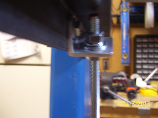


I just noticed that the store label on the outside of the support angle gives an optical illusion of the angle being slightly bent in the above photo - wierd! I will remove this later to keep it from paying tricks on my mind as I build the wings.
With that side done, it was time to finish the other side. First was the bottom side hole - same as the first side - 9.25 inches below the mounting hole for the support angle. I measured and marked the spot just as before, and drilled the hole on the first side of the stand. This next pic shows what I think I tried to describe in earlier posts but may not have done so very clearly. Pics are worth a thousand words. THis shows how I measured the precise location of the first hole so I could transfer the dimensions over to the other side with reasonable certainty that they were the same. The straight edge is clamped so that it serves as a hard stop for the tape measure.


I transferred the dimensions over to the other side of the stand. This time the hole lined up almost perfectly. I then drilled the other 1/4 inch mounting hole in the angle bracket, and it was time to assemble the hardware for that side.
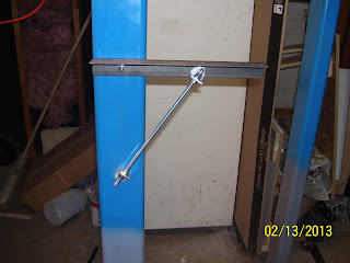

And then the final touch. To prevent the rough steel angles from scuffing the wing spars during assembly on the stand, I placed Gorilla tape over the tops of both angle supports. The spar will be clamped in place on one end, and the outboard end of the wing will be attached to the opposite support angle via yet another support angle that will be drilled and mounted to the last wing rib, and susequently to the top of the attached support angle bracket. Again, easier to see than to describe.
Anyway, feels good to complete the brackets for one wing stand. Now I just have to measure and drill and mount the supports for the other stand. Since tomorrow is Valentines day, adn the following day is my local EAA chapter 301 meeting night, I may not get this done until this weekend, but it will get done. You keep celebrating the small victories, and one day they all add up to one huge victory celebration when that first flight is entered into the logbook and engrained into your memory forever. Still looking forward to that day, whenever it may be.
Working last night and again tonight, I was able to finish fabricating the threaded rod brackets and drilling the remaining holes in the other side of Wing Stand # 1. So the supports are essentially done for one wing stand. this first pic of the threaded rod brackets after I drilled one 1/4 inch hole and one 5/16 inch hole for each bracket.

Next is a series of pics showing the completed assembly of one support:


I just noticed that the store label on the outside of the support angle gives an optical illusion of the angle being slightly bent in the above photo - wierd! I will remove this later to keep it from paying tricks on my mind as I build the wings.
With that side done, it was time to finish the other side. First was the bottom side hole - same as the first side - 9.25 inches below the mounting hole for the support angle. I measured and marked the spot just as before, and drilled the hole on the first side of the stand. This next pic shows what I think I tried to describe in earlier posts but may not have done so very clearly. Pics are worth a thousand words. THis shows how I measured the precise location of the first hole so I could transfer the dimensions over to the other side with reasonable certainty that they were the same. The straight edge is clamped so that it serves as a hard stop for the tape measure.


I transferred the dimensions over to the other side of the stand. This time the hole lined up almost perfectly. I then drilled the other 1/4 inch mounting hole in the angle bracket, and it was time to assemble the hardware for that side.


And then the final touch. To prevent the rough steel angles from scuffing the wing spars during assembly on the stand, I placed Gorilla tape over the tops of both angle supports. The spar will be clamped in place on one end, and the outboard end of the wing will be attached to the opposite support angle via yet another support angle that will be drilled and mounted to the last wing rib, and susequently to the top of the attached support angle bracket. Again, easier to see than to describe.
Anyway, feels good to complete the brackets for one wing stand. Now I just have to measure and drill and mount the supports for the other stand. Since tomorrow is Valentines day, adn the following day is my local EAA chapter 301 meeting night, I may not get this done until this weekend, but it will get done. You keep celebrating the small victories, and one day they all add up to one huge victory celebration when that first flight is entered into the logbook and engrained into your memory forever. Still looking forward to that day, whenever it may be.
Subscribe to:
Posts (Atom)