Showing posts with label Nutplates. Show all posts

Sunday, March 31, 2019

Prep for Final Assembly and Riveting of the LEFt wing LE

As mentioned previously, the next step was to remove the vinyl inside the LE skin that I have left on all this time to protect the metal. I do not prime the entire interior surface to try to save some weight. The epoxy primer overspray and cold temps have left this remaining blue vinyl in a state that is very difficult to remove. Here is one of the problem sections that I needed to remove:

I was not able to take my finger nail and lift up the edge to peel it away like I normally can. The primer hardened onto the metal next to the vinyl making this difficult. So what to do? I still need to remove this protective vinyl because if left on it can cause corrosion to occur by trapping moisture and debris between the vinyl and the metal. Unfortunately the vinyl only chips away and it won't peel off as one piece. 

After pondering this for a bit I remembered that I have a heat gun around here somewhere. I thought that maybe I can use that to heat up the glue on the back of the vinyl to at least soften it up a bit and see if that would allow it to separate from the metal easier. So I got this bad boy out and gave it a whirl:
After mucking with the setting son the gun and experimenting with how hot things could get, I finally came up with a procedure that involved holding the gun at a safe enough distance and heating up the entire surface of the vinyl as well as the edges until the vinyl softened up enough for me to peel it away. What I found out real quick is just how fast and how hot that heat gun can heat of the vinyl AND the metal. SO after figuring out how not to burn myself too much, this actually started to work pretty well:
Here is the sheet removed from the inside of the LE skin:
And here are some shots of what happens to some of the remnant primer 

It separates from the vinyl and rolls up into little flakes that have either a positive or negative charge that causes them to stick to the LE skin. After I got all the vinyl sections in between the ribs removed I had to use a shop vac to remove all the primer flakes.

The next task was to remove the red ink with the metal specification information. Normally isopropyl alcohol removes this very easily, but it has been baked on for so long that t was no longer doing a very good job, so I switched to using acetone, which worked very well. I was not too worried about wiping the acetone on some of the epoxy primer because that stuff, once hardened, is almost impervious to anything, and is very hard to remove with anything but acetone rubbed very deep and hard into the primer to soften it. What little acetone did come into contact with the primer evaporated away before it did any harm to the primer. I used paper towels and small dab of acetone to remove the red ink on the metal. Why remove this? Well some say it can lead to corrosion over time as well, but others say it doesn't harm anything. UP to now I have always removed it from the metal as part of the final assembly prep, so I did it here as well.

Once this was all done, it was time to final assemble the LE for what I hope will be the last time. the subskin and two inboard ribs were re-clecoed to the LE skin again, and the entire LE was placed back on the wing spar due to one thing I read in the instructions about making absolutely sure that the rear edges of each LE rib were exactly straight. The only way I knew how to ensure that was to re-cleco the LE back onto the wing spar again so that all the rear rib flanges were in alignment with the spar web, and then I can remove it again and start riveting the entore LE together. 

I also needed to put it back on the wing spar because I wanted to screw down the new removeable section using those new nutplates I just riveted to the subskin, so that I could check the actual "installed" fit of everything. As with everything else, I found out that after I screwed down the removeable section, all of ONE of my screws sat nice and flush to the skin exactly as planned. One of the screws was not laying flat on once end, suggesting that either my screw dimple or the hole or the nut plate was not properly oriented for the screw. It is not so bad that I feel that absolutely must fix it, but it may end up bugging me enough to the point where I am going to fix it anyway. This means removal of the subskin again to reset another nut plate, and of course it is one of the corner nut plate that are difficult to set.

I may actually try to set the new plate with everything mounted on the wing, but I am still debating that with my self. Here is the string of pics showing the part as originally envisioned, planned, and realized:

And finally, the same non-matching fit that I have been dealing with shows up once again after the part is screwed down onto the subskin, but the inboard side is quite flush and looks really good. I think I can still flush out the other side with the LE by applying a little fiberglass magic later on. 
Overall I am happy that it seems to have gone together pretty much how I envisioned it. Here are some final shots of the screws through the nutplates on the inside of the subskin:


Thursday, March 28, 2019

More Nutplate Hell and Creative Clamping

After several days I was finally able to finish riveting all 20 nutplates to the subskin. Man did that turn into a royal pain in the ass. As of the previous post I had made it to the last side and had messed up the rivets on the last, most-forward nutplate along the edge. This is where the skin starts to curve at the very front, which makes trying to set straight rivets with a rivet squeezer a bit of a challenge. I think I managed to finally get it after drilling bad rivets out a couple of times.

With the side nutplates installed, it was now time to tackle the hard part - the remaining rear-most nutplates on the top and bottom sides of the subskin. I could not use a rivet squeezer on these because they are too deep into the center section of the subskin for any of my squeezer yokes to reach. SO that meant that it was time get out the rivet gun and the bucking bar - something that I have not done for a very, very long time.

I decided I did not think I needed to practice on anything, because I was able to get the air pressure setting correct for the rivet gun. Looking back I wish I would have been more experienced about that when I riveted the horizontal stabilizer skins onto the frame. It hangs up on the wall in my garage so that every time I walk in I have to look at it, and I cringe every time that I do. That is because I literally beat the shit out those skins because my pressure was too high, and almost every rivet attaching the skin to the forward spars has this large skin dimple from over hammering the rivet gun on the skin. By the time I got to the elevators I had pretty much figured that out, but I literally pounded the HS skins almost to death..

Anyway, with the air pressure set on the gun, the next step was to figure out how to clamp everything down tight. I ended up deciding that using my bench vise should allow me to set everything up to use both hands to buck these rivets without needing to worry about securing or holding the part. Here are some pics if what I came up with. IT involved the bench vise, a small 2x4 for the smooth front side of the skin, and a custom sized much smaller piece of 3/4 inch plywood for the back side. All of this had to be positioned very carefully to ensure that there was enough space for the rivet gun and bucking bar, and to allow everything to be clamped tightly down without deforming any dimples in the skin. With so many dimpled rivet holes in this custom part, this became a challenge at times.

The top part of the skin was easier because there were not as many holes to dodge while clamping it all down:
I used a bar clamp to provide stiffness and resistance on the top part of the skin. This was the difficult part of trying to use the bench vise for this large piece of aluminum. The vise only provides a small amount of depth, so the top part of the skin remains very flimsy unless it reinforced with something such as the wood that I used.

On the front side I had to make sure there was enough room for the rivet gun:

And here is shot of the back showing how I had to be careful about the size of he wood  used and how it was positioned to avoid smashing or deforming any existing dimples. The other concern was of course making sure that I had enough room to use the bucking bar. This did not prove to be much of a problem until I got to the corners where the first side nutplate is located relatively close to the rear-edge nut plate in the corner. 
And here is yet another creative clamping method where I was able to use the access plate hole on the bottom side to insert another bar clamp for added stiffness. 

The stiffness is needed because, regardless of who you may talk to or what you may read in a book, you HAVE TO apply some pressure on the rivet gun and the skin to ensure that it will NOT bounce when the rivet gun is activated. This is what directly causes badly set manufactured rivet heads where they sit noticeably proud of the dimple because the underlying skin was allowed to flex and bend each time the rivet set was pounding against the skin. The part needs to be clamped in such a way that any movement of the part is severely restricted. This is the only way that you are able to buck good quality rivets. Sometimes the temptation is such that you do not take the necessary steps to ensure that everything is properly clamped. Then you basically pay the price for the mistake, and you have to drill out bad rivets and try again.

I was able to get all of the nutplates riveted in place, except of course for the very last one, which was a corner nut plate on the bottom side of the subskin. This one proved to be so difficult that I think I drilled the rivets at least 4 times and replaced the nutplate once because it was deformed beyond acceptable limits on one side or the other. I think I must have drilled out no less than a dozen rivets and replaced 3 nutplates during this whole exercise. The top side ones went pretty well, but the bottom side was another story. In fact, I had screwed up the rivets on the last nut plate so many times that the shape and condition of the dimples in the subskin. it was so bad that I was now unable to secure the nutplate in place with a cleco so that the flange on the nutplate would sit flush against the skin. I had to start using tape to hold it in place. When this did not even work, I had to take out my other arsenal of tools. Luckily I was able to use my 4 inch no hole yoke on the bad nutplate on the bottom of the skin. I mounted it on the hand squeezer because I was not having any luck with the gun and bucking bar, and the pneumatic squeezer was too bulky to fit as well. 

So my only choice was to use the hand squeezer so that I could position it and take my time to set the first rivet to make certain I did it correctly. I was able to set the first rivet on one flange just enough to hold it in place where I could then finish it up with the gun and bucking bar. The manufactured head of the rivet ended up sitting just proud of the skin on one side, but I had a plan for addressing that. Part of the plan was to try to use the rivet gun to move it a bit more flush to the skin - this only partially worked.

With the first rivet set as well as could be expected, I then was able to properly set the second rivet with the rivet gun and bucking bar. The corner rivets only allowed just enough room to insert my small tungsten bar in between the two nutplate flanges on the corner. One slip and the rivet, skin, and nutplate would be history. In fact, he bar did slip one time and slightly creased the skin, but I deemed it as OK since it was a dull crease with no apparent stress risers, which means I just barely stopped the rivet gun in time. Had I not done so this entire subskin and the planned project would have come to a screeching halt.

Here re the pics of the finished nutplate rivets on the ear side of the skin. First the nicely set ones on the top side:
And then the less-nicely set ones on the bottom side. Some of the primer was knocked away from all the repeated pounding from multiple attempts to set the rivets, and if you double click on the pic you can see it in more detail and tell very easily which rivets caused me the most trouble. 

And here is the back side of the nutplates all riveted together.

Now, remember that slightly proud rivet I mentioned earlier? Well, here was my solution for that. A long time ago I was at Harbor Freight, an I just happened to stumble on this next little gem - a watchmakers hammer. I used the round headed side of this hammer to lightly tap on the edge of the rivet that was sitting proud, and I was able to get it to sit much more flush after just a few taps with this hammer. This hammer was critical for this because the small size and weight of the ball end of this hammer was just about perfect for ensuring that it only contacts the surface of the rivet head and not the surrounding skin. If it was too large it would dent the surrounding skin, but I found this little hammer to work exactly as I thought it would:
And finally, here is just a small sampling of all the tools  ended up using to accomplish this seemingly small task. As I said before, most of this was pleasant to work on, but those few times when things got difficult, they got VERY difficult. I could not risk damaging or screwing up the subskin because it has required so much customization that there was no way at all that I would be able to take the time to try to fabricate a new one, nor would I even want to. If that part were to be compromised beyond use or repair, I would abandon the entire modification and return to a stock LE without even looking back. Too much time and too many delays with this to even think about starting it all over again.
And here is he pile of drilled out rivets and damaged nut plates that I had to drill out and replace, sometimes repeatedly:
So yeah, I got really good at drilling out AN426 rivets again, too. Anyway, I was able to pound some rivets again, so that is always good. And, more importantly, that step is now complete, which allows me to move on to the next step. 

So next up s to remove all the remaining internal sections of vinyl covering on the inside of the LE skin that I have left in place all this time. Unfortunately this is proving to be difficult, because some of he overspray from the epoxy primer that I used has hardened the vinyl in those areas, and as a result is very difficult to pry up a corner of the vinyl and keep it going so that I can remove the entire thing without it breaking apart. That vinyl has also been stuck to the skin since 2010 when I ordered the wing kit, and I already know that the longer it stays on the glue makes it harder to remove as it gets older.

After that vinyl gets removed it is finally time to rivet the left wing LE together. Great  - more curved surfaces t deal with. I can hardly wait...….

KPR

Tuesday, March 19, 2019

Started Riveting the Nutplates for Securing the LE Removeable Section to the Subskin

I started out by free-handing the attach rivets for the first couple of edge nutplates on the subskin with the pneumatic squeezer, but even though I was able to set these OK, I did not like the risk and the inability to hold that beast of a heavy squeezer with only one hand while holding the subskin in the other. So before I set any more rivets, I had to rig up another custom method of clamping the subskin to allow the proper support and positioning of the part for riveting the nutplates on. Here is the initial setup using my padded 4x4 wood blocks (3 of them) and the bar clamps similar to what I have done before:
I had to reposition and reclamp the part for each new rivet, sliding the subskin as close as I could get it to the clamped blocks without causing interference between the squeezer and the clamps. I also added a second clamp on the other side to tighten up the structure. This allowed me to use both hands on the squeezer to set the rivets.

I used my 3 inch yoke which had enough clearance from the edge of the subskin to set all of the edge rivets on both sides. The 4 remaining nutplates on the rear edge of the top and bottom of the subskin will have to be bucked - oh boy - there is something I have not done in a while. 
Also shown in the above pic are the flat rivet sets that I used. The thing I hate about nut plates is that the rivets that attach them are on either side of the center shaft for the screw. This does not leave very much room for positioning the rivet sets so as to be centered over the rivet shaft without being too far over to one side to ram into the screw thread shaft, thus destroying the nutplate. ON the other side of the nut plate exists the possibility that you could slide too far away from center, causing an incorrectly set shop head on the rivet. IN order to avoid hitting the screw shaft, I needed to use a 3/8 inch wide flat set (on the top of the yoke in the above pic), and the 1/2 inch wide flat set on the bottom which goes over the manufactured head of the rivet. This means that the squeezer must be positioned as centered as possible to avoid either condition described above.  And may I say that it is a royal pain in the ass having to use a flat set that is that small to do all the mashing of the shop head. 

Lets just say that so far I have had to drill out about 4 rivets because of this, and I may have to replace one nutplate after damaging the edge of it when the squeezer slipped while squeezing, to the point that I am not happy with it. The other thing that sucks about this session is that I cannot position the squeezer very easily in such a way that I am able to pull against the manufactured head with the top of the yoke, so that the ram that moves from the bottom does not displace the part or cause the squeezer to slip out of position as it travels upward. Instead I have to keep the extremely large squeezer body on the outside of the part, which forces me to do the opposite by placing the moving ram on the manufactured head of the rivet instead of the shop head. The result so far is 4 badly set rivets that needed to be drilled out and replaced. 

The good news is that I was able to set almost all of the edge nutplate rivets on both sides of the subskin using the pneumatic squeezer. And the rivet heads seem to be pretty flush on the subskin surface where the removeable section will be sitting on top of them, so I was happy about that as well. Here is the result of one side of the edge nut plates installed:
I should also mention that I used my rivet gage to determine the size of the rivet that I needed - the winner was AN426AD3-4 rivets, These set very nicely in the dimpled nutplate flanges and left more than enough of a correctly sized shop head. 
You can tell that I have riveted anything in a while, because I also forgot one other cardinal rule that I had established long ago when using the pneumatic squeezer to set the rivets. The instructions for this tool say to set it to 90 psi, but  found that this tool has just too much force at that setting, and this can cause the tool to shift out of position or ram with such force that it almost damages the part. So I found long ago that setting the air pressure to 75 psi works a lot better. It does not activate as violently as it does at 90 psi, and it still maintains enough force at that settings to more than adequately set AN426 rivets.  Here is a shot of the air pressure setting for posterity later on.
Another shot of all the clamps in position
And finally a shot of a successfully set nut plate using this setup. I made it all the way to the last rivet on the last edge nutplate and managed to screw that up because I got too fatigued and wanted to finish it. So I drilled that one out and will reassess that one tomorrow. Then I will need to come up with yet another custom clamping setup so that I can buck the remaining rivets on the remaining nutplates  When that is done, the subskin goes back into the LE skin for the final time, where all those millions of dimples will also be riveted together into a solid LE with all the custom work completed.


Sunday, March 17, 2019

Round 3 - Making a Template of the Removeable Section of the LE

yup - another round of lousy weather, delays - yada yada yada has yielded very little work on the project in over a month. It's been way too cold to work in the garage, and we just experienced a lovely thing that some moron decided to call a bomb cyclone several days ago that resulted in our first real blizzard in the Denver area in a good long while.

Anyway, to pick up where I left off, I had one last chapter in this whole removeable section fabrication  to cover before I move on to what I was finally able to get done today. After finally getting a part sized, trimmed, fitted, and drilled with correctly positioned mounting holes to #30, I now needed to make a template. The problem was that the part that I was finally happy with had been fitted to the LE, and as a result it was now slightly curved, and this presented some problems with trying to fabricate a new plat piece of metal out of another slight curved piece of metal.

As a long story short, I decided that I could probably use some weights to re-flatten the "good" part just enough for me to draw a matching pattern onto a piece of .025 flat metal again, just as I had done to make the part that I have finally deemed "good." the big deal about all this was trying to take advantage of the precut "factory" edges of the new metal, because their cutting machines and processes are much more accurate than mine. I wanted to do this so that at least two of the edges would be absolutely straight. This minimizes any additional work I need to do to trim and shape the other two edges to get a good fit. The other issue is to ensure that the holes are drilled in the correct spots, and that the curves in each of the four corners are radiused correctly.

At the end of it all, it made me really appreciate metal parts that are precision cut, punched, and fabricated by precision tools. What follows is a series of pics showing how I went about making the template from which I would be able to make as many more of these as desired. First up was a process of taking the now partially bent "good" part and setting into position against the two good edges of the .025 sheet using some cleco clamps and my bucket of very heavy #40 clecoes. This did a pretty good job of flattening the part back down so that I could trace the edges onto the new sheet and also match drill the holes around the perimeter.
This turned into a very involved exercise of precise clamping and drilling, moving things around as necessary and re-clamping again. I used the wood from my drill board to match drill the holes and then cleco both parts directly onto the drill board.
After it was all done the holes were deburred and the top and bottom and edges were marked, and it was cut from the sheet using either shears or my Dremel tool cutoff wheel. The problem with this next one is that I ended up trimming to much material away from the corners and edges and so this one did not fit very well and I had to make yet another one.
So I ended up making another one where I intentionally added a bit more material on the edges to ensure that I would not come up short. So after making 3 more of these crazy things I finally ended up with a keeper that I could use for flat template that could be used to accurately make more of them as necessary. Trimming the corners to have just the right radius is also a challenge. 

Here are some pics of the horrible trimming job I did tht forced me to have to make yet another template:


Yeah they are blurry but you can still see how bad the gaps are. This was just not acceptable so I started over.


SO now we can fast forward to today. The problem was that I could  NOT continue with anything on the LE until had this template made correctly, because the next step in this process was to upsize each of the #30 holes in the good part to #19 for the #8 dimples and screws that will be inserted into them to attach the part to the subskin. 

So with a "good enough" template now completed, I reattached the good part to the LE and then re-clecoed the LE skin securely onto the wing spar to make certain that everything was in the proper position  before drilling the holes. Then I took the #19 drill bit and started upsizing each of the #30 holes in the removeable section as well as the subskin underneath. I used the black colored clecoes to secure the section to the subskin as I went. I had 20 holes to upsize and only 10 clecoes, so I had to be creative about how I did this. I upsized all the holes on the top side of the LE first, followed by the bottom holes. Then I used my deburring bit and my edge deburring tool to ensure that the holes were very clean and smooth, just as I had done for the tank attach holes long ago, so that the #8 dimples would not have any cracks in them. 

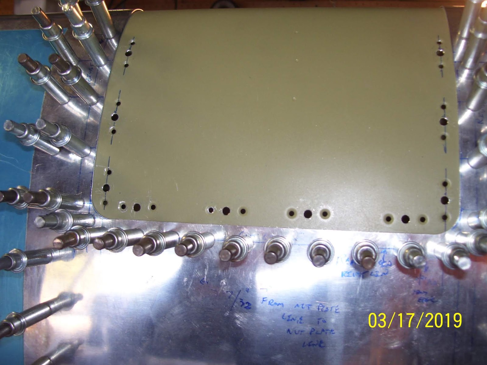
Here are pics of the top and bottom sides after the holes had been upsized and the removable section was removed. the #40 holes for the rivets that will hold each nut plate were already drilled and dimpled long ago, so this exercise is just for the 20 (10 top and 10 bottom) center screw holes.

And here are the top and bottom side pics of the removeable section after I dimpled all the holes on both sides

I was glad that all the dimples seem to have come out well. While setting the dimples in the removeable section was relatively easy since it is not bent very much, forming the #8 dimples on the subskin turned out to be yet another interesting exercise to set these dimples. It required using both hands and my head to position each hole over the male dimple die in my C Frame and keep the metal away from the ram, so that I could use the ball peen hammer to set each dimple by whacking it a few times. Just as when I previously set the dimples for the tank attach nutplates on the subskin several months ago, the holes nearest the front of the subskin closest to the bend were the hardest to set.
 
With the dimples on the removeable section done the next step was to remove the LE from the wing spar for what I hope is the absolute FINAL time before I permanently affix it to the wing spar, and remove the subskin so that I could set those dimples as described above. This also went reasonably well, despite the awkward contortions of my hands and head required to set them.
 

I also took a pic of the new "final" flat template, and the label I wrote on it to ensure that I would be able to tell months from now that I would be able to to tell which template is the "good" one as I proceed to create the same thing for the right wing LE. However since I doubt that I will end up with everything sized exactly the same on the right wing, I think I will end up making a customer one for the right wing as well, when the time comes.


With all the #8 dimples done, it was time to cleco the K1100-8 nut plates in place on the subskin s I could start riveting those in place. I did not quite get to that today, so that will be my next task that I will hopefully complete next week. Here is the subskin with all the nut plates clecoed into position:

I cant believe that I am finally at a point where I can start to assemble the left wing LE for the final time once these nut plates have been riveted. That's all for tonight. Hopefully much more progress next week.

Monday, December 10, 2018

Subskin prep - Drilled and Dimpled Remaining nut plate rivet attach holes and Reassembled the LE

Today was a busy day at the factory, but for the amount of progress I made today you would probably not believe me. I finished sanding the edges of the cutout section of the LE skin smooth and straight, and used the combination of my pneumatic rivet squeezer and C-Frame tools to dimple all remaining #40 nut plate rivet attach holes on the subskin. I had to switch from my flange yoke to the standard 3 inch yoke to be able to reach all the rivet holes along each side of the subskin, and this worked out nicely. I had to use the C-Frame to reach most of the rear-most rivet holes on both sides of the subskin, and this also worked out well.

Unfortunately I had to use the #30 cleco method to secure the nut plate to the subskin so that I could align and drill the holes for each nutplate on the top side of the subskin, just as I had previously done on the bottom side. Just as before, I had trouble keeping the line of rivet holes in alignment with other straight edges, and some of them got a bit slanted. As I stated before, these holes are just for the rivets that attach each nut plate to the subskin, so the MOST important hole is actually the center hole where the screw will be inserted, and not the rivet holes.

I used the same technique to mark the alignment of the rivet holes on the top as I did  on the bottom, by placing a straight edge along the center line of each #30 screw hole and drawing short lines on either side of each hole that I used to align the rivet holes of the nutplate after it was clecoed to the subskin through the screw hole.


I drew the lines along the sides on the outer side of the skin, and drew the lines for rear nut plate holes on the inside of the skin, just as before. As shown from the pic above, I also came up with a different clamping and prep method of drilling these rivet holes. This time I really did not care so much about trying to rig up something so that I could clecoe the nutplate in plate as shown above, and then ensure that I was drilling each rivet hole into a piece of wood. I reasoned that any slag or burr on the holes would be removed by my deburring tool afterward, and so this time I chose NOT to waste a substantial amount of time coming up with ridiculous ways to ensure I could drill each hole into a piece of lousy wood. This worked out fine, except for the slight shifting of the nutplate because the clecoe just does not apply enough force to keep the drill from moving the nut plate around. SO I much prefer using the nut plate jig which prevents this from happening, but since I was not yet ready to drill the #30 hole to a #19 hole yet, which the jig uses as a pilot hole, I could not use the jig tool.

I used my 4x4 clamping blocks to provide some height to allow the cleco mounted from the underside as shown in the next photos to clear the table and saw horse ends, and the next pic shows how I clecoed the first hole after it was drilled, which keeps the second hole from moving around as well, so that both rivet holes are in alignment with each other.


As each set of rivet holes was drilled I detached the nut plate and moved it to the next hole and re-clecoed it in place, and repositioned and reclamped the subskin as necessary to retain some rigitidy in the subskin near the nut plate locations so the drill would not slip or cause the skin to warp and the hole to become mis-aligned. Here is the series of pics as I continued to drill each set of nut plate holes along the sides:


With the sides done it was time to drill the rear nutplate hole. I had to flip the subskin over and reposition and reclamp it once again. I was able to use the edge of the table to help position the skin so that the clecoe underneath butts up against the edge, keeping the skin nice and stiff while drilling.


The last pic above actually shows the holes after I dimpled them. The mot important thing to call attention to here is that I have NOT yet final drilled the screw holes to the proper size because I need to make a template first so that I can fabricate a properly sized part that will replace the cutout section in the skin. I cannot final drill the screw holes to #19 and dimple them for a #8 screw until the template has been created and at least 1 or 2 .025 removeable LE skin sections have been fabricated and fitted in place. To do that I need the screw holes to remain at #30 for now. 

Next I had a bit more cutting, filing and sanding to do on the subskin. A long time ago I had marked the location where the hole for the tie down ring is located by tracing the hole I had already drilled in the LE skin onto the subskin, which, until today, had been covering up that hole. I used the cut off wheel o n the Dremel tool to carefully cut away the metal in this area, staying just OUTSIDE the drawn lines so that  could ensure that the subskin would have enough clearance to screw in the tie down ring. Here is the pic of that after filing, sanding, and rounding all corners was completed:
With most all of the subskin prep work done, it was time to reassemble the LE for what I hope will be the second-to-the-last time before it goes together permanently. the subskin was attached first using all the rivet holes that are not part of a rib flange hole. This gets the subskin in the proper position for the ribs. Then the two inboard-most ribs are clecoed to the subskin and outer LE skin. This process always takes some work because the ribs are a very right fit in this area due to the thickness of the subskin. Again, the goal of all this was to reassemble the LE with the newly cutout section in the skin that exposes the subskin that will be used to attach the removeable LE section.

Here is a series of pics I took to show the fit of the LE and subskin after remounting it all back on the wing spar again. Overall I was pleased, but the problem that I feared and mentioned in a previous post is exactly what I encountered. The outboard are of the cutout section of the LE skin shows a bit of a gap between the subskin and the outer LE skin, whereas the inboard section seems to be draped over the subskin fairly well. This will make fitting the removeable part a bit of  a challenge, but we'll see how that goes. I am not overly concerned about the gap because I think the rib in that area combined with the subskin provides more than enough support to keep the LE from deforming in any way as a result of this gap. In other aircraft designs, such as the Sonex for example, I know that their ribs do not even wrap around the contour of the LE skin. Instead, they stop well short of the very front of the skin so that NONE of the ribs have any rounded contour that wraps around the LE at all, leaving a void between the rib and the very front part of the LE skin.

As long as the shape of the front of the LE skin remains consistent across its entire span I do not see a problem with this. I think this will occur because the rest of the LE outer skin is stressed, so it retains most of its shape due to the tension of the bend that is force-ably wrapped around the top and bottom flanges of each LE rib.

First pic is the top side of the LE with the subskin now showing through:
Next are the inboard and outboard curves of the front of the LE skin showing the gap I mentioned between the LE skin and the subskin  on the outboard section. Both pics are takne from the top side of the LE:


The next set of pics is the same series taken from the bottom side of the LE


And finally 2 pics that show the clearance of the tie down ring hole through both the outer LE skin and the subsin after trimming it away from the subskin. Looks pretty good to me, but I may decide to wien both of the holes a bit to make certain that stresses placed on the ring from high winds etc. will not start contacting the edges of the LE sin in this area. The ring can be screwed in and out with ease.

So this was a day that was very long in the making. I had to wait 2 weeks for it to warm up enough in the garage to get to this point. took about 3 hours or so to do everything described in this post. Next steps are to make the file folder template and fit it to the cutout section of the LE, mark and drill the #30 screw hole locations in the paper template with the LE firmly mounted back on the wing spar, remove the template and use it to trace the new removable section of the LE onto a piece of .025 aluminum. I may decide to go buy some Home Depot grade stuff to practice on until I am certain that I have the outline of the part measured, cut, and formed correctly. My concern now will be what I need to do to make the curved front end of the removeable section match the curvature of the inboard and outboard outer LE skin. Not sure if I will need to apply some shims due to the gap, or if I will be able to pre-stress the removeable section similar to the outer LE skin so that it will retain its shape with the rest of the LE skin. Time will tell on that one.  Hopefully I will be able to get to that point this week since the weather is finally supposed to be warmer.