My Technical Counselor and former long time EAA Chapter 301 President Jim Elliot has been mentoring me through all this LE mod fiasco. I had to wait a couple of weeks for him to become available to come and visit the "almost" finished LE work, and he was finally able to come out last Saturday and take a look. He is a Mooney aircraft owner and has helped several people build different makes and models of experimental airplanes. He definitely knows his way around an airplane, and with evaluating potential affects of modifications such as mine. More on that in a bit.
Since I knew I had to wait for a bit for him to be able to come over, I started preparing (for about the third time now) to get back to work on the fuel tanks. So although I have not posted in while, I have still been very busy thinking, reviewing, and planning for re-engaging on the fuel tanks to get those behind me as soon as possible. his started with a review of many previous posts where I actually started on the left fuel tank because you needed to match it up with the LE to check alignment and drill some holes in the T-712 mounting brackets for the wing spar and the rear tank baffle. This little journey took me clear back to posts from the Fall of 2017. About the last thing I remember about the tanks was fabricating the tank stiffeners for the bottom of the fuel tank skin, and countersinking skin-to-rear baffle holes per the plans.
After reviewing the stuff from the past, I ended up coming up with a list of new additional questions that required answers from Vans. As a side note, to date I have order at least 2 proseal tubes, a small sized can of proseal, and a full sized quart of proseal - ALL of which have shelf lives that have long since expired, so they will not be used to seal any part of my fuel tanks, and I will need to put in an order for more proseal yet again. Sucks to be me I guess - that's about the only way I can sum that up.
Many of these additional questions are questions that you do not see either asked or answered by others, but I find it quite strange that others are not asking the same questions. Anyway, to make sure that I don't lose the content, I am posting them here for myself and anyone else following my blog that might also appreciate the info:
385b and c SW fuel senders - for left and right - is it correct that the potentiometer scale/meter on c version for the right tank will be reversed (facing forward instead of to the rear, when installed on the side of the tank, or should the scale for both still appear toward the rear of the tank when installed correctly.
Vans says this backwards orientation is normal - important thing is that they both point down when installed either on the end rib or the rear baffle plate.
Am I supposed to scuff the back side of the sender flange of each sender if I am going to proseal it directly to the tank rib (NOT use the rubber gasket or cork as recommended by many who have been there before.)
Vans says not needed.
The left sender seems to have a dead spot at the end of travel of the arm (empty indication) - either no ohms reading at all or much higher (300 ohms or more - much higher than expected 240 ohms per the plans.) The right sender seems to be indicating correctly per the palns info. Ordered both SW senders from Vans on 4-16-18 order # 74191. SW says has a 2 year limited warranty - how do I proceed with a replacement. Go through Vans or direct with SW?
vans - Contact SW directly to replace it
Left tank will be flop tubed, so sender will be in bay #2 in rear of baffle.
1. Did I do a lot of extra unnecessary work by cutting the big hole in the aft of the end rib, when I found out that the sender needed to be placed in the second bay via the baffle in the first place.
Vans -still good to have access t that bay due to the trap door and the flop tube/anti hangup bracket attachments.
2. With the sender in the secnod bay of the rear baffle, that means that the only way I can service that sender if necessary is to pull the entire tank, correct?
Vans - correct - you will have to pull the tank to service the sender that is mounted this way
3. For tank baffle mounted sender, do I need to cut another big round hole in the second bay AND use a reinforcement ring (T-407) as well, or just the hole big enough for the sender to fit in?
Vans says nope - no reinforcement ring or big hole needed - just a hope big enough for the sender to be inserted/mounted directly onto the rear baffle plate web. No reinforcement ring needed because the baffle plate is thicker/stiffer than the rib web.
4. Do I need to use another reinforcement stiffener ring for the T-411 cover plate on rib T-703 if no sender is being mounted in that hole, or can I just mount the cover plate, with nut plates mounted on the rib web itself instead of the combo of the rib web and the reinforcement ring?
Vans - would still use the stiffener ring here as the rib is not very thick and alot of strngth is removed by cutting that big hole.
5. Depth of tank for SW sender specs to determine what size to cut the rod - what dimension should I use for that (tank depth so I cut the rod to the correct length?
Vans - just clamp the sender in place and measure to determine based on the area where the float will be traveling.
6. Since the left tank sender will go in the rear tank baffle, do the dimensions of the float wire change from original plans for mounting in the rib on the side? Any issues with clearance of the bottom stiffeners when mounting the sending in the rear tank baffle?
Vans - measure to be sure, but should not be a change or a problem as far as they are aware.
7. Do you know a part number for a more malleable proseal for access plates that is not as hard as normal proseal to remove??
Vans - they do not use it and did not know the part number of hand - said to check Spruce and others.
8. Grounding the sender - how is this grounded to the airframe if you have the tank baffle or rib web, proseal, and the flange of the sender on the thin later of proseal. Are we supposed to run an additional ground wire from one of the sender mounting screw holes to one of the tank attach bolts or something similar?
Vans - Use a lock nut with the cut flanges that bites into the metal on the underside of the screw head and on the sender flange as it gets mashed down during screw tightening to establish contact for a good ground - so additional wire should be needed, even if screws are prosealed. Do it on all screws or just one or something in between?
As far as the tech counselor visit is concerned, Jim took a look at my unfortunate demise on the LE. Said that it is a dent and not a crease, but that it did deform the outer skin and the subskin. Then we had a conversation about acquiring an autobody or planishing hammer and a dolly that may have to be customized to try to pound (actually TAPPED) out to try to reform the skin back to the shape that it was in before. Unfortunately I can see where my unbelieveably STUPID idea t just keep pounding on the skin with the rivet gun when the rivet was not setting properly has indeed flattened it out a bit. So as a result, if I want to continue with the LE mod using what I have done thus far, I now get to learn a new skill that involves removing dents and reshaping metal, and I probably have to custom-make yet another tool = more wasted time.
So I went to local NAPA store, found a planishing hammer with a rounded head (NOT the kit you find at Harbor Freight, that only has flat headed hammers), and a Toe dolly that, when I fitted it up against the curvature of one of my LE ribs that I took with me to the store, looks like it will almost perfectly conform to the curvature of the LE skin/subskin/rib as long as it is held in the correct position. This is probably going to require a helper to hold the dolly in position while I tap the outer skin and hope like hell that I don't just deform everything beyond reasonable repair.
The last part of our visit was spent having a heart to heart about the possible structural impacts of what I am trying to do, and if I should go ahead and contact a DER (Designated Engineering Representative) to come and look at my invention and provide some further experienced insight on what I am doing. I wanted to go ahead and finish this mod regardless of the ultimate decision about its feasibility, just to see what it would take. At the end of the day I am not certain that this is a safe thing to do, and may still decide to abandon it all together. But I'm not throwing in the towel on the mod just yet.
I've got some parts to order from a number o different vendors so I am also putting that list together. I'll have some pics on the next post that show the damage from the F'd up riveting job more clearly, and the tools I am going to attempt to use to fix it.
Showing posts with label Technical Counselor. Show all posts
Showing posts with label Technical Counselor. Show all posts
Monday, May 20, 2019
Monday, April 9, 2012
Wings 16 Total 479 - Almost there....Still countersinking the left wing spar
Had to pause a bit for my son's birthday and Easter with the family - both very worthy causes as far as distractions from the airplane build are concerned. Nice Spring weather also makes it hard to isolate oneself in the garage as well. Regardless, I was able to carve out a few hours between yesterday and today to keep drilling and countersinking the remaining holes in the left wing spar.
First, I managed to get my airplane-themed drawer knobs installed on my bench drawer. I will most likely paint the drawer front at some point, but this'll have to do for now. I thought these looked very cool.


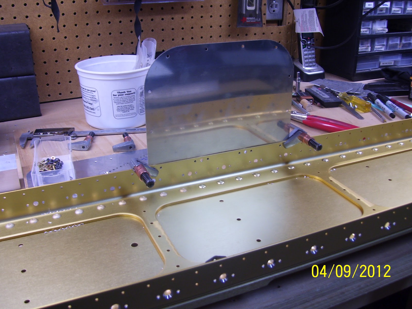
Here is the top flange of the left wing spar with all the fuel tank skin holes countersunk. The top side is much easier because it does not include the different size holes for the inspection cover plates that are mounted on the bottom. They all came out rather well I think.


This next one shows the back side of one of the smaller #6 screw holes as it appears from the inside or back side of the spar flange. All of the nut plate triplet sets of holes have to be deburred after they are drilled and countersunk. The important thing to note about this next pic is that these are holes that end up coming very close to the edge of the spar, so if you are not careful you maycountersink too far so you need to pay attention to the diameter that you set your countersink tool to. The back side pic is misleading because it still shows that the hole has plenty of edge distance on the spar flange. What you don't see is the other side that was countersunk.

Next are the two different nut plates and the corresponding screws that are used for each one.The smaller one is for the #6 inspection plate screws on the bottom, and the larger one is for the #8 screws that will hold the fuel tank skins to the main wing spar. One curious thing to note about the larger nut plate. It is a K1100, which means that is made with a dimpled cavity to accept a dimple or screw countersunk screw head. The only problem is that these nut plates are installed on the bottom or flat side of the spar flange, so there is no need for using a dimpled nut plate. In fact, I would argue that it provides less concentrated surface area around the screw shank than a normal, non-dimpled K1000 nut plate would. I'm sure this is yet another oversight from Van's. Oh, yeah, I think the other ones are a little cheaper too - go figure.

Next is the partially drilled, deburred inspection hole access plate or cover - 3 per wing for a total of six. See DWG 17A for the RV8 plans (Drawing numbers for other models may vary). I gave you fellow builders that one because I am such a nice guy, since Vans does not mention this drawing where they should in the plans.... go figure.....
The holes that are dimpled on one edge are for the #6 screws that mount to the spar flange, drilled with #28 bit, and dimpled with a #6 dimple die. The remaining holes around the other 3 sides are to be drilled with a #19 bit, and dimpled with a #8 dimple die. Why the different sizes for one inspection plate? I am sure Vans has a reason, but they don't tell you what it is. Go figure.......

Here I have temporarily clamped the dimpled cover plate in place on the spar. There are cutouts in the main wing skins that already allow the space for this plate

And next I attempted to take a shot that shows the gap between the cover plate and the spar flange because the countersunk holes are not quite deep enough due to their close proximity to the edge of the spar flange. I can probably try to tweak the countersunk holes a bit, but I don't have a lot of room to work with, adn the dimples only go into the countersunk holes are half way right now.

Here is a shot of the 36 inch long, 1.5 inch x 1/8 inch thick aluminum angle that I was able to use to do most of the left wing spar. I did run out of real estate on the angle for the last 15 or so holes on the top, so I ran to HD and picked up another 36 inch long angle, as well as a 48 inch long angle that will allow me to drill more holes than before without moving it. I will use this one on the right wing spar.

Next is a shot I forgot to take when my tech counselor, John Linz came for a visit last week. I have admittedly been very lazy about putting the parts back up on the shelves because I kind of like looking at them all just laying there, ready to be put together and assembled on a fuselage. Someday..........

I set them up this way so that John could inspect each part as much as he felt he needed to.
And lastly, here is my deburring tool. Every one of the drilled or countersunk holes requires a little deburring on both sides of each spar flange. The outside holes I could get with my cordless drill no problem, but the inside holes I could not reach with my drill, even when cocking it 90 degrees into a gun shape. The spar is just not quite wide enough to fit the drill inside the spar web to countersink the inside holes, so I did each one of those by hand. Worked out fine, but it just makes your fingers really sore after a while. Just have one more side on the left spar to debur, then I can switch the left for the right and start the drilling all over again. So I am about half way done with the holes. In the wings right now (pun intended) are the rear spar assemblies and the fuel tanks.

First, I managed to get my airplane-themed drawer knobs installed on my bench drawer. I will most likely paint the drawer front at some point, but this'll have to do for now. I thought these looked very cool.


Here is the top flange of the left wing spar with all the fuel tank skin holes countersunk. The top side is much easier because it does not include the different size holes for the inspection cover plates that are mounted on the bottom. They all came out rather well I think.


This next one shows the back side of one of the smaller #6 screw holes as it appears from the inside or back side of the spar flange. All of the nut plate triplet sets of holes have to be deburred after they are drilled and countersunk. The important thing to note about this next pic is that these are holes that end up coming very close to the edge of the spar, so if you are not careful you maycountersink too far so you need to pay attention to the diameter that you set your countersink tool to. The back side pic is misleading because it still shows that the hole has plenty of edge distance on the spar flange. What you don't see is the other side that was countersunk.

Next are the two different nut plates and the corresponding screws that are used for each one.The smaller one is for the #6 inspection plate screws on the bottom, and the larger one is for the #8 screws that will hold the fuel tank skins to the main wing spar. One curious thing to note about the larger nut plate. It is a K1100, which means that is made with a dimpled cavity to accept a dimple or screw countersunk screw head. The only problem is that these nut plates are installed on the bottom or flat side of the spar flange, so there is no need for using a dimpled nut plate. In fact, I would argue that it provides less concentrated surface area around the screw shank than a normal, non-dimpled K1000 nut plate would. I'm sure this is yet another oversight from Van's. Oh, yeah, I think the other ones are a little cheaper too - go figure.

Next is the partially drilled, deburred inspection hole access plate or cover - 3 per wing for a total of six. See DWG 17A for the RV8 plans (Drawing numbers for other models may vary). I gave you fellow builders that one because I am such a nice guy, since Vans does not mention this drawing where they should in the plans.... go figure.....
The holes that are dimpled on one edge are for the #6 screws that mount to the spar flange, drilled with #28 bit, and dimpled with a #6 dimple die. The remaining holes around the other 3 sides are to be drilled with a #19 bit, and dimpled with a #8 dimple die. Why the different sizes for one inspection plate? I am sure Vans has a reason, but they don't tell you what it is. Go figure.......

Here I have temporarily clamped the dimpled cover plate in place on the spar. There are cutouts in the main wing skins that already allow the space for this plate
And next I attempted to take a shot that shows the gap between the cover plate and the spar flange because the countersunk holes are not quite deep enough due to their close proximity to the edge of the spar flange. I can probably try to tweak the countersunk holes a bit, but I don't have a lot of room to work with, adn the dimples only go into the countersunk holes are half way right now.

Here is a shot of the 36 inch long, 1.5 inch x 1/8 inch thick aluminum angle that I was able to use to do most of the left wing spar. I did run out of real estate on the angle for the last 15 or so holes on the top, so I ran to HD and picked up another 36 inch long angle, as well as a 48 inch long angle that will allow me to drill more holes than before without moving it. I will use this one on the right wing spar.

Next is a shot I forgot to take when my tech counselor, John Linz came for a visit last week. I have admittedly been very lazy about putting the parts back up on the shelves because I kind of like looking at them all just laying there, ready to be put together and assembled on a fuselage. Someday..........

I set them up this way so that John could inspect each part as much as he felt he needed to.
And lastly, here is my deburring tool. Every one of the drilled or countersunk holes requires a little deburring on both sides of each spar flange. The outside holes I could get with my cordless drill no problem, but the inside holes I could not reach with my drill, even when cocking it 90 degrees into a gun shape. The spar is just not quite wide enough to fit the drill inside the spar web to countersink the inside holes, so I did each one of those by hand. Worked out fine, but it just makes your fingers really sore after a while. Just have one more side on the left spar to debur, then I can switch the left for the right and start the drilling all over again. So I am about half way done with the holes. In the wings right now (pun intended) are the rear spar assemblies and the fuel tanks.

Thursday, April 5, 2012
Wings 7, Total 470 - Testing countersink depth and Tech Counselor Visit
So I thought that I would be all set to start countersinking the nut plate holes last night - right up till I reviewed several more VAF posts discussing the method that should be used to do this. I originally thought that I had this all figured out and I was ready to go ahead and use my method of setting the countersink depth so that the dimple in the skin would sit inside the countersink hole and the skin would rest properly over the flange.
I paused after reading several posts that started mentioning that Vans no longer recommended using the test dimple/countersink method because too many people were over-countersinking the holes in the flange. So instead of using the dimple test method, Vans started recommendng a range for the sze of the diameter of the countersink, which should be somewhere between .365 and .375 inches. Apparently they mentioned this in an old RVator article, which is the monthly magazine that Van's was creating until they stopped in 2010. Most folks are apparently still adhering to this recommendation from Vans and they split the difference of the range and settle for countersink diameter of .370 inches. The argument being presented against this approach was that with this diameter, the skin/dimple does not quite sit flush, and there is a small amount of spring back.
Apparently Vans says that this is OK, and several other builders said that this works out just fine. Then came the other glaring comments about making test pieces to determine what the correct countersink depth should be. This ended up hitting me like a ton of bricks - how stupid would I be to conduct "experiments" on the actual parts of the airplane. Have I not learned anything yet?
So after a deep sigh, and a realization that I might not get too much actual hole drilling done on the wing spar, I put the idea of experimenting on the actual wing spar completely out of my mind, and got out a couple of pieces of scrap aluminum from my trim bundle that I received with the empennage kit. One of them was a piece of flat 1/8 inch thick aluminum plate, and the other was a piece of .032 inch thick aluminum which is supposed to be the thickness of the Wing tank skins, although I thought that they were a bit thicker at .040. I drilled a series of #19 holes in the thick aluminum. This was my countersink test piece. Then I drilled a similar hole in the .032 inch piece, deburred the hole, and set a #8 dimple in it. Then I took my microstop countersink tool and started countersinking the hole in the thicker aluminum with a shallow depth at first, and increasing the depth a little at a time in between measurements with the digital caliper.
I performed a couple of different tests. The first was to countersink until the dimple and the skin would just sit flush in the countersunk hole with little or no movement. This seemed to occur at a dimater of about .396, or just shy of a .040 diameter. This is almost 3/100s larger than the recommended size of .370. SO then I countersunk another hole to the recommended .370 diameter, and I could detect just a small amount of spring back of the dimple, but I could still almost squeeze the dimpled skin flush with the thicker skin containing the countersunk hole. Since this is the dimension that recent builders seem to be going with, I decided to do the same.
Now for some really crappy pics to take you through the process - they came out blurry for some reason.
First is the diameter of the #8 dimple in the .032 thick test piece, as shown from my digital caliper it is .375 inches wide, or just slightly larger than the .370 dimension of the countersunk hole.

Here you see the math that I used to meaure the dimater of the base of the #8 dimple

And here are the test countersunk holes, one of them too large, and the other set to the .370 recommended diameter as shown:

And the top side of the #8 dimple

And here are the #8 screw dimple dies:

And here is the #19 Countersink bit that I used:

I got 2 of the 3 drawer knobs that I ordered for the new tool drawer - very cool!

Reflections are reaking havoc on this next pic, but this is the first countersunk hole that I drilled on the spar flange. One down, many mnay more to go:

And finally this the actual method/process that I used to drill the holes and countersink it:
1. Started with a # 21 drill bit to drill completely through the center hole and the aluminum angle on the back side
2. This creates a hole that can then be easily drilled out with the #19 drill bit, which is the final size hole you want for the #19 countersink bit. So you switch bits and final drill the hole to #19.
3. With the correct depth set on the microstop countersink tool based on the work on the test pieces, insert the pilot of the #19 countersink into the hole and countersink the hole.
4. Check the countersink for even diameter all the way around the hole. This does leave the bottom edge of the hole rather razor sharp, which raises concerns from some builders, but Vans apparently dismisses this and indicates that this is the way that it should be.
5. Wash, rinse, repeat for the remaining holes. Oh yeah, forgot to mention that you need to remove the clecoes and reposition the clamps as necessary to ensure that the countersink tool can sit flush to the spar flange.
So now that the first one is done, the rest of them should go fairly quickly I think. I need to get oe more shot that I did not take tonight of the screw head sitting inside the countersunk hole and also inside the dimple. It sits pretty flush inside the dimple, but sits noticeably deeper inside the countersink than level with the top of the flange.
And finally, My EAA tech counselor visit this evening. John Linz, a fellow EAA chapter 301 member, was kind enough to look over my my mostly completed empennage parts. Apparently everything is good enough to press onward, even with all the dings and scratches noted. John is a great guy, and we talked a lot about building and flying while he was here. He also told me some of the horror stories he had encountered or heard about from various other builders over the years. Pretty crazy stuff. I am glad to report that I don't think I fell into that category!

It is always a good feeling to have other experienced builders critique your work at various stages. You must have built at least one airplane in order to receive the designation as an EAA technical counselor. Nothing beats first hand experience. After the visit was done, some paperwork was filled out, and he was on his way after visiting/reviewing everything for about an hour or so. Thanks for looking everything over John!
Now back to the wings!
Tuesday, April 3, 2012
Wings 5.5, total 468.5 - Drilling wing spar nut plate holes begins
Feels good to hear the sound of the drill carving out aluminum holes again. Before I could do that, however, I had to perform those laundry list items I mentioned in my previous post.
-Marked the wing spar so that orientation is clearly marked so that front/rear/left/right/top and bottom are identified. I still need to write down the serial numbers that Van's stenciled into the spars as I am sure I will need these when I order the fuselage kit to get the matched center section.


- Took a piece of 1/8 inch thick x 1.5" x 3 foot long aluminum angle I purchased from HD a long time ago and clamped it flush to the inside edge of the bottom spar flange using my cleco clamps and some small bar clamps. I would recommend this size angle for this job because it sits nicely overthe rivet heads that attach the wing spar together. The 1/8 inch thick angle is what will provide the additional material that the countersink pilot can insert into as the countersink carves out the holes for the screws and the nut plate rivets.


Note that upper and lower spar bars on the underside of the above picture only go about 1/3 of the way down the length of the spar, making it a bit awkward to sit on the bench with the bars facing down and the flanges facing up. The next step was to clamp the spar to the workbench so that it won't move while applying pressure on the drill to drill through the spar flange as well as the thicker angle on the back side of the flange. I placed some additional blocks of wood under the spar web about half way down the spar beyond the length of the spar bars to help level the spar on the bench. I then used my larger bar clamps and more wood blocks to secure the spar to the bench.

Then there was nothing left to do but start drilling some holes. I started on the bottom flange after taping the crevace between the spar bars and the spar flange to avoid getting small aluminum chips stuck in there. I chose to start with the #40 holes for the rivets for each nut plate, since I was still mulling over just exactly how to drill the center holes to ensure the countersinks were set correctly. Having a 3 foot long piece of angle allowed me to simply drill all the rivet holes and cleco them in place as I went. I was able to cover most of the nut plate rivet holes on one flange.
Then came a moment of pause and deep thought. Originally I said I was going to mark the center hole location with a sharpee and then remove the angle and try to locate the center point for a #30 hole. I then though back to what Dan said on his site - that he used a number 21 countersink bit instead of the #30, which has a pilot that more closely matches the diameter of the prepunched hole in the spar flange. I then further realized that this hole thing about using the #30 countersink was based on Vans recommended method of clecoing the nut plate onto the spar flange and then using that #30 countersink whose pilot would fit inside the nut plate hole just about right.
Since I am not going to cleco the nut plate to the spar flange, the whole idea of using a #30 countersink bit kind of goes right out the window. It makes absolutely no sense to try to use a countersink bit that has a pilot that is smaller than the diameter of the hole that is needed for the screw that will ultimately have to go in there. In fact, the prepunched center hole seems to be about the size of a #22 drill bit.
So I shifted my plans just a bit. The plan now is to follow Dan's lead and the info on my drill guide chart from Cleaveland Tools and use a #21 drill bit to drill the center hole through the spar flange and the aluminum angle for each nut plate location, followed by a #19 drill bit and a #19 countersink bit. This should keep the countersink pilot exactly where it needs to be to ensure that they turn out correctly.
My drill chart from Cleaveland tools shows that an AN509 R8 screw should be predrilled and clecoed using a #21 hole initially, followed by drilling a #19 hole and countersink for the proper clearance to insert the screw. I did get both drill bits and the #19 countersink bit in my tool kit, so this should be easy work for tomorrow. (*Ed note - I previously wrote that I did not have a #19 countersink bit, but I checked again as I put the cars in the garage and closed up the factory for the evening, and found that I actually DID have a #19 countersink bit in my arsenal of cutting tools, so Cleaveland Tools rocks yet again. Had I realized that earlier, I might have drilled a few countersinks, but oh well.....)
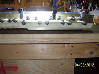
These last pics are of the rivet holes drilled and clecoed. Note that the last pic shows a set of holes that are at opposing angles to each other near the root of the spar. This is because this is the area where a series of about 4 ribs are installed very close together which is the wing walk area where everyone will be stepping on the wing to enter and exit the plane someday. As such, there is not enough room to install these nut plates in the same linear fashion as the others, so that is the reason that they are angled.
I also scheduled my Tech Counselor visit with John Linz this Thursday evening to inspect the work I did on all the empennage parts. Sure hope that goes well. John lives just a mile or so up the street from me, and he told me over the phone that I must be the closest tech counselor visit he has ever made. What can I say, EAA folks just seem to naturally congregate together, and the EAA/RV community seems to be growing in this area, which is a great thing.


-Marked the wing spar so that orientation is clearly marked so that front/rear/left/right/top and bottom are identified. I still need to write down the serial numbers that Van's stenciled into the spars as I am sure I will need these when I order the fuselage kit to get the matched center section.


- Took a piece of 1/8 inch thick x 1.5" x 3 foot long aluminum angle I purchased from HD a long time ago and clamped it flush to the inside edge of the bottom spar flange using my cleco clamps and some small bar clamps. I would recommend this size angle for this job because it sits nicely overthe rivet heads that attach the wing spar together. The 1/8 inch thick angle is what will provide the additional material that the countersink pilot can insert into as the countersink carves out the holes for the screws and the nut plate rivets.


Note that upper and lower spar bars on the underside of the above picture only go about 1/3 of the way down the length of the spar, making it a bit awkward to sit on the bench with the bars facing down and the flanges facing up. The next step was to clamp the spar to the workbench so that it won't move while applying pressure on the drill to drill through the spar flange as well as the thicker angle on the back side of the flange. I placed some additional blocks of wood under the spar web about half way down the spar beyond the length of the spar bars to help level the spar on the bench. I then used my larger bar clamps and more wood blocks to secure the spar to the bench.

Then there was nothing left to do but start drilling some holes. I started on the bottom flange after taping the crevace between the spar bars and the spar flange to avoid getting small aluminum chips stuck in there. I chose to start with the #40 holes for the rivets for each nut plate, since I was still mulling over just exactly how to drill the center holes to ensure the countersinks were set correctly. Having a 3 foot long piece of angle allowed me to simply drill all the rivet holes and cleco them in place as I went. I was able to cover most of the nut plate rivet holes on one flange.
Then came a moment of pause and deep thought. Originally I said I was going to mark the center hole location with a sharpee and then remove the angle and try to locate the center point for a #30 hole. I then though back to what Dan said on his site - that he used a number 21 countersink bit instead of the #30, which has a pilot that more closely matches the diameter of the prepunched hole in the spar flange. I then further realized that this hole thing about using the #30 countersink was based on Vans recommended method of clecoing the nut plate onto the spar flange and then using that #30 countersink whose pilot would fit inside the nut plate hole just about right.
Since I am not going to cleco the nut plate to the spar flange, the whole idea of using a #30 countersink bit kind of goes right out the window. It makes absolutely no sense to try to use a countersink bit that has a pilot that is smaller than the diameter of the hole that is needed for the screw that will ultimately have to go in there. In fact, the prepunched center hole seems to be about the size of a #22 drill bit.
So I shifted my plans just a bit. The plan now is to follow Dan's lead and the info on my drill guide chart from Cleaveland Tools and use a #21 drill bit to drill the center hole through the spar flange and the aluminum angle for each nut plate location, followed by a #19 drill bit and a #19 countersink bit. This should keep the countersink pilot exactly where it needs to be to ensure that they turn out correctly.
My drill chart from Cleaveland tools shows that an AN509 R8 screw should be predrilled and clecoed using a #21 hole initially, followed by drilling a #19 hole and countersink for the proper clearance to insert the screw. I did get both drill bits and the #19 countersink bit in my tool kit, so this should be easy work for tomorrow. (*Ed note - I previously wrote that I did not have a #19 countersink bit, but I checked again as I put the cars in the garage and closed up the factory for the evening, and found that I actually DID have a #19 countersink bit in my arsenal of cutting tools, so Cleaveland Tools rocks yet again. Had I realized that earlier, I might have drilled a few countersinks, but oh well.....)
These last pics are of the rivet holes drilled and clecoed. Note that the last pic shows a set of holes that are at opposing angles to each other near the root of the spar. This is because this is the area where a series of about 4 ribs are installed very close together which is the wing walk area where everyone will be stepping on the wing to enter and exit the plane someday. As such, there is not enough room to install these nut plates in the same linear fashion as the others, so that is the reason that they are angled.
I also scheduled my Tech Counselor visit with John Linz this Thursday evening to inspect the work I did on all the empennage parts. Sure hope that goes well. John lives just a mile or so up the street from me, and he told me over the phone that I must be the closest tech counselor visit he has ever made. What can I say, EAA folks just seem to naturally congregate together, and the EAA/RV community seems to be growing in this area, which is a great thing.


Subscribe to:
Posts (Atom)