Showing posts with label Edge Rolling. Show all posts

Saturday, February 25, 2012

451 hours - Rolling the left elevator

A big thank you to my fellow aviator and neighbor Kevin Shepard and his father Bill. Kevin answered my call for assistance to get the left elevator leading edges rolled. His father was visiting and wanted to take a look at my build, so of course I put both of them to work as soon as they arrived. It sure is helpful to have many sets of extra hands during this process.

Only differences between this episode and the one for the right elevator is that I used only 2 sections of overlapped gorilla tape instead of 4 to attach the water pipe to the skin, and I used the 3/4 inch OD pipe for both top and bottom skins instead of the small one for the bottom and the larger one for the top. I did not mean to use the same size pipe on both sides - just slipped my mind. Anyway, I think it worked out fine this time. 2 pieces of tape worked great adn the bends came out just fine. Oh yeah, I also did not roll the edges very far at all. Maybe 35 degrees tops. This worked out very well as the edges of the skins were much closer to where they needed to be by the time I finsihed hand forming the rest of the bends oin each section.

The left elevator is also a bit different than the right in that it is essentially split into 4 sections instead of three. This is due to the slot that is cut in the inboard section to allow for the manual trim tab cable, should one desire to install that trim system. Since I am installing electric trim I will ahve no use for this slot, but that is the way the skins come from the factory. This actually makes bending the leading edges a little easier since it reduces the overall size of one of the sections. That middle section is still a bear to get positioned correctly.

I almost have everything positioned where I want it. I will tweak it a bit more tomorrow before I final drill the holes and set the rivets on both elevators.

This pic shows clecoes installed on all rolled sections"


And I reprimed the bottom skin of the right elevator. Should be able to close that up tomorrow as well. The primer on the left elevator actually did not come off when I removed the tape from the bar and the skin. Must have had enought time to cure hard to the metal or something. So at least I only had to reprime the right elevator.


I am still a bit concerned about the burs from drilling the holes in the right elevator, but I think I knocked them down as best I could.. I think I will use the reamers on the left elevator instead of using the drill bits to see if I can keep those holes a little cleaner. 

Friday, February 24, 2012

A p.S. to the previous post

I forgot to mention in my previous post that I went searching for some information in my blog way back during the rudder final assembly, and I found what I was looking for. I was wondering all this time while finishing up the elevators how I managed to NOT strip away all the primer on the leading edges of the rudder when I rolled those LEs.

The answer: I rolled the bottom or underside edge of the rudder first, and THEN I applied the primer afterward. So the tape never touched the primer. So if I would only have spent the time to carefully research my own previous posts, I would have realized this, and would have avoided having to repeat the steps to reprime the leading edges. Live and learn  I guess.

Somebody asked me if the tape should be able to strip the primer off of the metal like that. My answer: The gorilla duct tape I am using can strip just about anything from anything IMHO, especially from cold aluminum with a primed surface that was stressed during the rolling action. I will be deburring the holes and positioning the LEs so I can reprime them again. I will have to remask the entire elevator just as before and repeat the primer application. Just a minor setback, but a setback nonetheless.

Thursday, February 23, 2012

448.5 hours - Right Elevator LE skins finally form fitted - drilled holes to #30

Man ya just gotta love this February winter weather we are having. The TV folks said we should get about a half inch last night. Woke up to 9 inches of the stuff on my driveway - another dig out - yippee. Oh, and then the winds were hurricane force around here for 2 days prior to that.

Anyway, I managed to get a few things done in the airplane shop tonight before it got too cold. I worked on the middle section of the right elevator, and finally got the skins to lay pretty flat on top of one another. Then I drilled the rivet holes - #40 first, followed by #30, for the pop rivets that will close everything up. I stopped at that point because I still need to re-prime the inside skin before I close them up for good. A little primer and deburring some holes, and I am done with the right elevator. (well, almost.....)


I also needed to go back to the left elevator for the third time and set my rivets a bit more. I did not get them squeezed quite well enough on the first or second attempt, but this time they are set to my satisfaction.

Tomorrow I will finish up the right elevator and Roll the LEs on the left elevator.

Tuesday, February 21, 2012

Elevator LE Pics from last night

So here are a couple of pics of the leading edge roll experience for the right elevator. The first shows some residual waviness of the mid section that I need to resolve. Problem is that this means that the top skin (the one that overlaps the bottom), needs to be pushed down a bit more, and this unfortunately means that I need to reverse the skins so that the bottom is on the outside and the top is on the inside. This is the only real way that you can apply enough force to the skin that needs to be bent. Switching the skins around becomes much more difficult when they start to overlap each other. I also need to reapply primer to the bottom skin edge, so at least I have two reasons for switching the skins around. Sure hope it is worth chewing up my fingers and hands again to finish this up. Did I already say that this is the my least favorite part of this build.


Those gaps have got to go -almost there.

Next is the entore elading edge. The top and bottom sections are laying down fairly well now, so only the middle needs some work. Oh yeah, and I still need to do the remaining 4 secttions of the Left elevator.


Monday, February 20, 2012

447 hours - finishing the LE roll on the right elevator

So after devoting an entire nice building weekend to the completion of my 2011 taxes, I finally got to go out to the shop tonight and continue working on the dream. I had partially completed the roll of the leading edge of the elevator. Now came the hard part - forming the final curve by hand for the bottom and middle sections.

I must say that I agree with others that have come before me that say that the middle section is the hardest one to finish. It makes sense if you think about it. The bottom section is the largest, and it is also a fairly long stretch of metal. The fact that the skins are larger at the bottom due to the taper of the leading edge (skinnier at the tip and wider at the root), means that it is a bit easier use your hands to work with it and form it the way that you need to. The tip section, by contrast, contains the smallest length of skin, as well as the smallest radius of all the sections. Even though it has a smaller radius than the bottom section, which generally makes it harder to work with, the short length of the tip section also makes it very easy to form into the final position for riveting.

The middle section, on the other hand, has a smaller radius, which makes it hard to get fingers and hands in all the right places to work the metal, AND it is also a very long section of metal. This results in a great deal of resistance on this section of skin. It wants to act more like a spring than a piece of metal that can be easily shaped to final form with your bare hands. It takes some creative work with your hands to get this section to fit correctly.

I managed to get the bottom and middle sections rolled into final position to the point where I am almost satisfied with them. The top middle skin needs a bit more work to remove some separations from the bottom skin - a few tweaks in just the right places to push the skin down a bit further to seal the gap. Unfortunately this is a bit more difficult than it sounds, especially when the top and bottom skins start to overlap with each other as they get closer to their final positions.

I'll post pics tomorrow since I'm too tired to do it now. Sure felt good to work on the plane again, even if my fingers, hands, and arms are tired from all that intricate metal forming!

Thursday, February 16, 2012

446 hours - Let the rolling begin

There is nothing like a complete computer melt down due to a virus and tax season to put a damper on your efforts to build an airplane. It's been a rough week all around, but I am back in the saddle and have a few pics from last weekend to get caught up on. I basically started rolling the leading edge of the right elevator and also did some prep work for drilling the center bearing bolt holes in the control horns once the leading edge work is done.

First thing is first - I needed to kerf the leading edges of the top skin on both elevators by using the edge roller tool. Same process as when I did it for the rudder. If you can look past all the smudged finger prints, you can see the small crease in the leading edge where the tool did its job. This is important for ensuring that the overlapped skins will rivet together cleanly, without curling up at the edges when the rivets are squeezed.


The idea is that you want to kerf the top skin so that when it compresses down on the bottom skin underneath the two edges will mate together nice and flat. The top needs to go on the outside to help shed water that may accumulate on the leading edges from rain or slush on those less than perfect weather days or when you need to wash the airplane.

the bottom skin needs to be primed where the skins will overlap. In the event that any moisture does penetrate this area you want to do your best to prevent sources for corrosion. Since this is a common area where corrosion can occur iit is in your best interest to apply some form of protection here. My advice is to wait untl after you bend the leading edge, because when I put duct tape over the leading edge with the primer to roll the edge, most of the primer got lifted off by the tape when I removed it. I need to go back adn see how I did this for the rudder because I don't remember having this problem when I worked on it.

Oh, well,  just have to respray it this weekend adn close everything up.


Now, in this next pic, can you tell if it is cold outside or not? I'm sure the hat and heavy coat don't give it away at all! BtW, this was in the garage with the heater cranked up full blast and the insulated garage door closed. Yup, it was cold. Wasn't goin to let that stop me though. I am taping up the bar on the mid section of the elevator in this next pic. Those that follow show the end result:


I decided to try some different techiques this time from the way that the rudder was done. Namely they were:
- I did not use the fancy bend table or the U bolts to hold down the bar on the table while I cranked on the bar to roll the skin. I ahve seen too many pics where everyone just tapes it up adn starts cranking, adn it all seems to turn out fine, so I thought I would try that approach. What I found is that you still have to be very conscious about pushing down and rolling at the same time so that you do not crease the skin where it joins the flanges of the forward spar.
- I did NOT want to roll it so far that the edges of the skins were already perpendicular to the spar before I even start closing them together. This got me into serious trouble with the rudder, because the inside skin ended up being rolled too far, aand I may still decide to open it up adn try to correct it a bit. But for now I will try to get the elevator skins right on the first attempt.

In fact, it turned out that even though I thought I had only rolled them just far enough, the inside skin still ended up being a bit over rolled. Personally I would say that you only need to roll the leading edge so tyhat it sits about 30-35 degrees up when you remove the bar and the tape. Don't even take it to 45 degrees or you will ahve the same problem I do. It really takes a lot of hand contouring the skins to get them to close up adn to ensure that the edges are laying flat against each other.  SO less is more for this part of the operation.

- I did find as others had told me that the elevator skins a re a bit easier to work with than the rudder. The technique to finish the rolling by hand is still an art form, however, and I can't even really describe how you need to do this very well. It is a combination of using the upper pad of the palm of your hand and the bottom portion of your fingers to gently and slowly push the initial bend of the skin closed until you finally reach the mid point where the top and bottom skins will overlap. The rest of the technique is figuring out how to push UP AND AWAY on the skin to keep it from forming a crease where the spar flange edge is located under the skin. Best way to describe this is to take it slow, and work up and down the entire section of the rolled skin. Then, when you think you have it just about right, keep bending it and rolling it with your hand some more so that the skins overlap each other, and only mnimal pressure is required to push the two skins together so that the rivet holes line up. I think that the whole trick to this is finding the sweet spot on the skin where you can apply pressure to keep bending it closer toward the mid section without risking
creasing the skin where it joins the spar flange.

Other than that, you pretty much just have to do it to understand how it needs to work.

-Roll only one section at a time. Yes it takes a bit longer to do this, but it is easier to roll smaller sections at a time.

-  I decided to use a smaller diameter piece of water pipe for the bottom skin, adn a larger diameter bar for the outer skin. I do like how this worked out. My outside diamters were 3/4 " for the inside skin (bottom), and 1 1/8 " for the top or outside skin. This seemed to position the top and bottom skins in such a way that allowed them to form better as you close each one up by hand.

-  I used gorilla tape to roll the edges. Be warned - it will remove the primer on your leading edge - very strong stuff that gorilla tape.

Next pic is about ready to flip the skin over adn roll the bottom mid section of the right elevator.

 The bar gets positioned against the skin so that the skin overlaps the bar by about half the diameter of the bar, or a bout half way across the bar for short :) Then you flip it over so the bar is on the bottom, attach some locking pliers to both ends, and crank away formly and consistently.

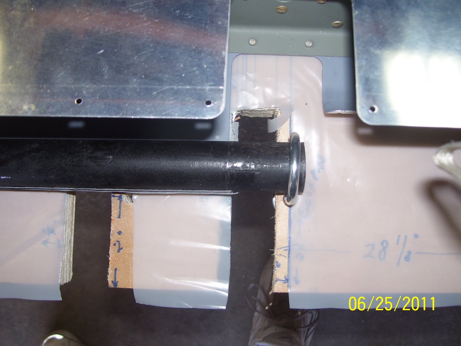
The only other thing to comment about is the length of the bars to use. This will be different for the rudder and the elevators, but about 20-22 inches seems plenty long enough to handle any of the control surfaces that need to be rolled. You need to have just enough bar hanging over the exposed cutouts where the rod end bearings are installed, but not so much that it extends beyond the other side of the cutout.

Here is the top section, which is the easiest to put together. I recommend doing this section first to give you an idea of what it will take to do the other sections.


And another important pic to illustrate the fact that the more help you have to perform this step, the easier it is to get it done. You mainly need at least one peson to hold down the skin on the back side becaue you need to move the taped bar assembly far enough forward to be able to attach the locking pliers to the bar to get a good roll. I found that I needed to start the roll, and then reposition the pliers again to roll it just a bit more. If nobody is holding the part down, the heavy bar will flip the whole thing right of the table and you will calling Vans to order more parts. My son Adam was gracious enough to help me with this.


And after both sides are rolled - the center and bottom sections are almost together. The remaining hand forming will close the gaps that you see and align the rivet holes so they can be clecoed together.


This next pic shows what happened to my primer when the tape was removed. Also shows that the edges were still a bit over rolled.

Monday, August 22, 2011

308 hours on the hobbs - Back to the Rudder (UGGGHHHHH!)

Had a bit of a scare the other day that I might have ruined both my VS and Rudder. Before I get into that, let's pick up where we left off before Oshkosh. I was almost done with the leading edges of the rudder. Lessons learned were:

The bend that was made with the bar  as described in my previous posts is only an INITIAL bend. You still have to do more bending (most end up doing this by hand) to get the holes in the edges to line up with each other so they can be pop riveted into place.

The plans clearly show that you MUST bend the leading edge skin near the edge of the spar flange in order to close them up so that the nicely curved edge is the proper distance away from the spar web. Very confusing since they spend so much time telling you how to bend the skin so that you DON'T end up doing exactly that.

Anyway, I used a techique of pushing down on the outside and up on the inside of the skin on the top to try to keep from creasing the skin next to the spar flange. Creases in the skin right next to the spar flange cause stress risers when flight loads are imposed on the control surface, which can cause crackes to form. I know this sounds confusing to you other builders out there. Just think of it this way. The initial bends were made with the skin down or on the surface of the board with the J bolts. The final bends are done in the opposite manner, pushing down on the skin on the top side to close the gap.

Here is a pic of all three sections closed up and pop riveted.

That pic does not show the crappy way that the middle and bottom skins turned out. To put it simply, the initial bend method that used (with the J bolts holding the bar and skin down flat on the table, worked SO well that I actually over bent the edges of the skins. They were initially bent so that the edges were almost at a 90 degree angle to the spar web. which the way that they should END UP when you are FINISHED bending everything. UNfortunately, as I stated previously, I still needed to finish bending the skins to close up the gap that still existed after the initial bends on both sides were completed. this ment that the edges of both skins ended up being well OVER 90 degrees to the spar web, causing them to curl up adn back toward the spar web just enough to caause me some severe headaches. This next pic shows the outcome. Notice the stressed edges of the inside skin in between all the pop rivets. This is the inside skin still wanting to curl back toward the spar web, but I am effectivey forcing the inner skin to attach to the outer skin. The result is that the edges of the skin are not flush with each other throughout the entire length of the edge:

I had problems getting some of the pop rivets to grab the inner skin so that it could be pulled tight against the outer skin. This was because in some areas the inner skin was curled inward  a bit more than the rest of the edge. So I was left with a decision, Replace the entire rudder skin since I had streched it too far, as one tech counselor told me, or devise a way to get the inner skin close enough to the outer skin so that the pop rivet would grab it. I chose the latter. I've spent way too much time on this damn thing already to even think about replacing the otherwise nicely attached rudder skin. I came up with a sort of lever that used 1/4 inch thick by 1 inch wide steel bar from HD, and a couple of small wood dowel sections, one taped to the end of one side of the bar, adn the other taped to the opposite side of the bar in a location where it could be used as a lever to push the inner skin outward after inserting it inside the curved section. Again, confusing as hell, I know. I forgot to get a pic of the lever so I will do that post again tomorrow. It actually worked fairly well, but required three people to get it to work correctly - one on the lever, one on the pop rivet gun, and one holding the rudder down so it would not move. Quite the operation but it did the job.

The LE skins are now all pop riveted into place. The only problem is that the middle and lower sections of the rudder LE are a bit concave when you look at them. This is due to the outer skin being pushed into the inner skin, and being drawn closer to the Spar web due to the over bent inner skin. Not happy with the outcome, but I have learned my lesson, so the elevators adn airlerons should come out looking very pretty.

Now on the next problem. After getting the LE skins closed up, I wanted to see that baby all hinged up on the VS. So I pulled down the VS from the garage shelf that I built, pulled out the 3/16" aluminum temporary hinge pins that I purchased, installed the rod end bearings in the rudder per the plans, and proceeded to insert the rod ends into the hinges. I found that the hinge holes were not quite large enough to fit the pins, After some research, I arrived at the conclusion that a 3/16 inch reamer would clear out each hinge hole enough to insert each hinge pin., and this seemed to work OK, but I noticed that each pin did have a little bit of resistance when going through the hinge holes. Then I swung it back and forth, with the RV grin all over the place, with the knowledge that had just completed my first full assembly of a stabilizer part and its corresponding control surface.

Then came time to remove the pins so that could move on to the elevators. Well, the bottom and middle pins all came out fine. but the top hinge pin would not budge. Short story is that a ridge had built up on the hinge pin due to inadequately reaming out the hinge holes, and this prevented it from coming back out of the holes. I ended up taking a small cold chisel that would fit in the confied space where the hinge is installed, and avery hard hammer, and banging the living hell out of it until it finally came out far enough for me to bend te hell out of the steel hinge half so that the bearing of the rudder would finally be free so that I could get he rudder off. Then I had to take my dremel cutoff wheel and leterally had to cut the tip of the hinge pin off in order to get it off of the hinge. I'll just close by saying that this ruined a perfectly good evening, and I almost ruined both parts in the process.

Further inspectiosn revealed that the hinges were still in good shape, and the rod end bearings on the rudder appear to be OK as well. SO I think I averted disaster yet one more time. The moral is that 3/16 " is a bit too SMALL for the 10/32 bolts that will eventually fit in them, as well as the 3/16" hinge pins that used. What I really needed was a number 12 reamer, which I did not have (have one on order as I write this). I did, however, have a number 12 drill bit. SO I used that to further ream out the holes. Just trust me when I say that the amount of material that was being removed by both the 3/16" reamer and the #12 drill bit, were basically dust particles, but apparently this was enought to make the difference in the pins fitting correctly or fitting too tightly in the hole.

Pics will help clarify this mumbo jumbo I hope:

Look towards the top of the pic on this one to see the sligt divet or inward bend of the skin. This is that concave result I spoke about earlier:
While I really wanted to try to put solid rivets in everything on the rudder, the trailing edge finally beat me into submission. You are given the option here to use pop rivets since the clearance in this area is so small. I was in the process of making a small bucking bar out of the 1/4 inch thick steel bar I mentioned earlier, but I finally caved in and said WTF and took the easy way out by using the pop rivets. Nice hole, eh?

Here is the original "happy moment" when I thought everything was coming to gether nicely. The hinge pins are in place and the two assemblies are now joined into one.
Next is a pic of the bottom temporary hinge pin in place.the temporary pins are used so that you do not put unnecesary wear and tear on either the hinge hole or the threads on the actual bolts that are used. the pins are smooth and are soft aluminum so they are not supposed to cause any damage or difficulty. (HA!)

And another seemingly happy moment, all before I realized I could not remove the rudder due to the stuck hinge pin:


And one last shot of the hinge pin assembly before I call it a night. Tonight I reattached the lead counterweight to the top of the rudder, hopefully for good this time. Torqued it to 30 inch pounds. Just a little powder coat touch up on the hinge brackets, and the VS and rudder can go to sleep for a while while crank out the elevators. 'Gnight all!

Saturday, August 13, 2011

Oshkosh Airventure 2011 Interrupts the build!

At about 302 hours I had rolled the leading edge rudder skins and did my best to finish closing the skins and pop riveting them together. It became clear that my initial rudder bend had actually worked so well that I ended up over-bending the skins. This created some problems when I tried to insert pop rivets in the last couple of holes in the bottom section. The inside skin would cleco OK to the outerskin, since the shaft of the cleco is long enough to reach inside, but as soon as I let loose of the cleco to try to insert the pop rivets. the inside skin would tuck away from the outer skin to the point that the pop rivet would not be long enough to grab hold of the hole in the inner skin, no matter how hard I tried to push in on the outer skin to close up the gap.

At this point I had about 1.5 weeks remaining till Oshkosh, and it felt like I was in hell week trying out for the Navy Seals just so I could finally get head up to Airventure 2011. The trailer was in the shop for some needed brake repairs which I had to force them to make twice before the problem was finally resolved. I learned after I got back that the tech that supposedly worked on them the first time was fired after failing to properly fix my problem. Apparently he had done the same thing to two other customers before me, so the shop manager cut him loose. I have read some stories about aircraft mechanics doing essentially the same thing while working on some airplanes. Just one more reason why I only trust myself to work on MY airplane when the time comes.

Work was also making me insane, since I was finishing up a project that I had worked on for the last 10 months. I was also in the middle of refinancing my house after seeing that interest rates had finally fallen lower than my current rate, so I was going through all that crap as well. When I hit the problem with closing up the rolled leading edges of the rudder, I had had enough for a while. The "so-close-but-yet-so-far routine with the rudder, combined with all the other madness that was happening around me, was really wearing me down. So I suspended the build to give me enough time to deal with everything else and placed also focus on preparing for Oshkosh.

This trip to Airventure 2011 was special for me. My youngest son Adam decided to tag along. I sort of half bribed him to come along by offering to charter a fishing boat to do some fishing on Lake Michgan, since we would be "in the neighborhood." In the end he had a great time, and even voluntarily mentioned to me that he could not wait to go back next year. That was music to my ears, and it was the reaction that had hoped he would have.


Some pics of where I left off on the rudder
All covered up to prime the leading edge of the inside skin:


Top and middle sections rolled, bent into final pistion by hand, and clecoed into place. Right side of the lower half still needs to be rolled. Many others before me had siad to do this in sections and don't try to roll all three sections at the same time. Exactly what I did.


Close up showing that the skins seem to be  butted up against each other nicely. What you don't see is the extreme curvature of the inside skin. So at least the kerf seemed to do its job by allowing the skins to lay flat against each other.

This last shot starts to show how "over" bent the inside skin became after I coaxed the skin into the final position. so that the holes of both skins would line up more or less in along the center line of the spar. If you look back at some of the early photos takne right after I performed the bend with tube, you will notice that the flanges and holes are almost 90 degrees perpendicular to the rest of the rudder skin. IN this pic, you now see just how much further I had to bend the skins over just so that the holes of both skins would overlap so that you can apply the pop rivets to close them up. Not real happy at all with the turn out of this. In fact, this is where I stopped taking pictures. You can just see the curl of the edge of the skin, and how it is obviosly now more than 90 degrees opposed to the spar, or starting to tuck further inward. This is the problem I spoke of earlier. The combination of hand forcing the skin into position the rest of the way and the over bent edges that resulted, is what caused the difficulties with the pop rivets. I will take more pics showing the crappy but still acceptable result of attaching the leading edges with the pop rivets, adn then you will understand even better what I am talking about. I will do pics of Oshkosh next cuz rehashing this process is painful, and I need some "happy" photos to take my mind off of the crappy result I got.


Thursday, June 30, 2011

Practice is over, time for the rudder roll

Here are some dimensions I used to cut the slots and drill the hole for the J bolt. I used a 1/4 inch clearance from the edge of the skin to keep the J bolt and the pipe wrenches clear of the skin. Lots of measuring going on here....


Preparing the plywood table - J bolts and rudder in place


And a slightly better shot


Did I mention a lot of measuring? These slots are so close to each other because I had to cut a different slot for the bottom section of the rudder. The distances between the middle adn top section are not quite the same as the bottom and the middle, so you have to make adjustments of you plan to do one section at a time, which I highly recommend.


Preparing to tape up the bottom section


All taped up and J bolts in place


and the other end....


and this shows the clearance from the edge of the skin...


Next shows the J bolt detail and how much I cut off. Make sure that the J bolt is high enough to clear the skin, and long enough to force the bar to stay in place.


Left side rolled. I actually rolled the top and middle sections at the same time since my pipe was long enough to do that, and then I rolled the bottom separately. Many people report that trying to do all three at once it quite difficult, since it takes a fair amount of force to bend that much aluminum at once. Better safe then sorry, so I chose to do separate sections. As you can see I am way short of the mid point, and I am frustrated at how much more work this appears that it will take to get these holes to line up so they can be riveted so I can finally be done with this assembly. The rudder is a lot of work, but if you just keep working on small portions of the assembly at a time, it will get done.


Next is something I overlooked yet again. More primer (yuck!) Thanks to Steve Riffe and a thread on VAF, I found another rudder pic from him that showed the primer applied to the outside surface of the underlying skin. This is an important thing to do since the outer skin will lay on top of this one, and once riveted will have to endure all sorts of vertical weather phenomenon, such as rain, snow, etc. Failure to prime or protect these critical areas may result in corrosion and the need to build a new rudder (double yuck). So, I ahve masked the outside edge of the underlying skin (the skin I just rolled), and will prime that edge tomorrow. Then I will proceed with the rolling of the other side of the skin, and then try to figure out how to force the edges to get close enough together to allow clecoes to be inserted in the holes, followed by pop rivets.... Hopefully I can call the rudder finished by this weekend, and then it will be on to the right elevator assembly.


Time for bed... To be continued as always....

Tuesday, June 21, 2011

292 hours on the hobbs Final Riveting and Skin Preparation for Rudder

So it's been a few days since my last post, but I ahve been busy on the rudder. I am beginning to wonder if this part will ever get finished. Lots of tricky riveting to do. One of the other things that has to be done is to roll the leading edges once everything else is riveted together. Below is a pic of a controversial edge rolling tool from Cleaveland tools. I had ordered this with my tool kit and had done some practice pieces with it, but not with very promising results. Then I ran into a whole bunch of posts on VAF. I found one thread that clearly explained the problem. There is such a lack of guidance from the makers of these tools that nobody understands how to use them correctly. Even the hints for homebuilders video on the EAA web site does not show enough detail about how to properly use the tool.

As the pic shows, there is a large thin flange on the top roller. This fits right against the edge of the skin being rolled, and needs to stay in that position while rolling the tool. The other trick to using this tool correctly is NOT to set the depth between the rollers too close or tightly together. People think that you have to get this really tight on the skin to achieve the desired slight bend on the edge. In reality it just needs to be tight enough to allow the roller to EASILY roll along the edge of the skin. Everyone expects to see a noticeable bend in the edge of the skin, probably because the diagram in the picture in the plans provided by Vans shows this bend to fairly distinct. The fact is that the bend is barely visible to the naked eye when done correctly. The tool creases the edge of one side of the skin just enough to counter-act the tendency of the skin to curl up when the pop rivets are applied. Most builders are complaining about how they cannot move the rollers, or how wavy the skin edge turns out, or how uneven the rolled edge is because it slips away frome the edge while being rolled. ALl because they are not using the tool correctly.

The fact is, if you use it correctly, it leaves a nice, even, small crease in the skin, exactly like it is supposed to.

Here is a set screw to make certain that the depth of the rollers stays set exactly where they need to be


And the Top roller that shows the flange that is kept flush against the edge of the skin, adn also shows the tapered part of the roller that actually apples the bend to the edge of the skin....


A bad pic attempting to show the gap between the rollers after snugging them up against the skin so that they were firm but not tight or smashing the skin.

Another not so good pic trying to show the edge of the skin after rolling was completed. You can just make out a slight bend on the edge. Again, you only roll the skin edge that will overlap the other skin. You do NOT roll both edges.

Many more pics to post, but it's late, so I will finish catching up tomorrow. As a preview, I will post pics showing the method I used to set the remaining 6 rivets on the edges of the support bracket, putting RTV on the stiffeners before closing up the skin, and a mock up/test tool that I created for practicing the rolling/bending of the leading edge of the rudder...